
Introduction
Ceramic-reinforced titanium matrix composites are widely used for high-temperature applications, such as functional aircraft and aerospace components, due to their enhanced elevated temperature strength, good creep performance, fatigue resistance, and wear resistance [Reference Xiao, Lu, Yang, Qin, Zhang, Wang, Zhu and Ji1, Reference Viswanathana, Lahab, Balanib, Agarwalb and Seala2, Reference Moya, Lopez-Esteban and Pecharromán3]. The influence of particle size of reinforcement on the strength, ductility, and failure mode of Metal matrix composites (MMCs) is well known [Reference jong4]. The large ceramic particles tend to crack during mechanical loading, resulting in premature failure and low ductility of the composites. Therefore, decreasing the ceramic particle size can lead to a substantial improvement in the mechanical properties of the MMCs [Reference Gu, Meiners, Hagedorn and Wissenbach5]. In recent years, considerable studies have been focused on the use of nanoparticles to reinforce metallic materials. Zhou et al. [Reference Zhou, Qiu and Jiang6] studied 2.0 wt% nano-sized TiN/Al–Cu composite by casting and found that its yield strength, ultimate strength, and elongation are higher by 20.5, 22.5, and 104.5% than those of Al–Cu matrix alloy. Wang et al. [Reference Wang, Li and Jiang7] prepared TiB2/TiN nanocomposites by the spark plasma sintering technique with an average grain size of 1 μm and 300 nm of TiB2 and TiN, respectively. The composite exhibited very clean grain boundaries, and no amorphous phase or oxide layer was observed. However, the mechanical properties of the composite were not investigated. Tian et al. [Reference Tian, Jiang and Liu8] fabricated Si3N4/TiN nanocomposites by hot press sintering and found that the flexural strength and fracture toughness depend on the amount of TiN. These properties increased for up to 15 wt% of TiN, but additional increase in its amount led to a decrease in thermal shock resistance. Apart from TiN-reinforced metal matrix composites, some studies on nano-sized TiC-reinforced [Reference Gu, Meiners, Hagedorn and Wissenbach5, Reference Wang, Qiu, Liu, Wang, Wang, Zhu and Jiang9, Reference Kim and Yu10, Reference Nemati, Khosroshahi, Emamy and Zolriasatein11] and the nano-sized AlN-reinforced metal matrix composites [Reference Gu, Wu, Jiao and Huang12, Reference Jin, Wang, Gao, Qiao and Jin13, Reference Sankaranarayanan, Habibi, Jayalakshmi, Ai, Almajid and Gupta14] were performed.
Ti exhibits high surface activity and hence reacts with most ceramics easily. Especially for Ti matrix composites, a ceramic reinforcement can exist stably in the matrix. TiC [Reference Lagos, Agote, Atxaga, Adarraga and Pambaguian15, Reference Qi, Wang, Zou and Wei16, Reference Mishina, Kaji, Ikegami, Ohishi and Hase17, Reference Gu, Meng, Li, Meiners and Poprawe18, Reference Wang, Qi, Zou, Zhu and Wei19, Reference Ota, Egawa and Izui20, Reference Rastegari, Asgari and Abbasi21], TiB [Reference Rastegari, Asgari and Abbasi21, Reference Ota, Yamazaki and Izui22, Reference Nandwana, Hwang, Koo, Tiley, Hong and Banerjee23, Reference Feng, Zhou, Jia, Meng and Rao24, Reference Feng, Jia, Zhou and Huo25, Reference Yoshihiro, Tsuchiyama and Takaki26], and TiC + TiB [Reference Ma, Wang, Liu, Li, Liu, Chen, Pan and Lu27, Reference Rahoma, Wang, Kong, Chen, Han and Derraji28, Reference Zhang, Zhang, Lin, Hou, Kong and Chen29, Reference Xie, Zhou, Jin, Wang, Jiang, Lu, Wang and Jane Wang30] dual-phase reinforced Ti matrix composites were studied the most. Given that most of these works were focused on the preparation method, mechanical properties, and formation mechanisms of the reinforcements, not much attention has been paid to the size of the reinforcements, especially for nano-sized particle-reinforced Ti matrix composites.
In previous studies on nanocomposites, most of the reinforcements were ex situ TiN, TiC, and AlN. Although in situ synthesized TiC reinforcing particles have been reported, these particles are generally micron-sized [Reference Jerome, Ravisankar, Mahato and Natarajan31, Reference Kumar, Mahapatra and Jha32]. In situ synthesized nano-sized TiN particles as reinforcement have rarely been reported. In 1991, Calka [Reference Calka33] found that the direct reaction of Ti with nitrogen can be achieved by the ball milling method. In 1997, Sherif El-Eskandarany et al. [Reference Sherif El-Eskandarany, Omori, Konno, Sumiyama, Hirai and Suzuki34] prepared nanocrystalline bulk TiN by ball milling and plasma sintering processes. The Ti–TiN composites synthesized from the nanostructured precursor powders studied by Wexler [Reference Wexler, Calka and Mosbah35] were prepared by ball milling and sintering methods in NH3 atmosphere. The Ti to TiN ratios were controlled by the change of gas pressure. The microstructure and mechanical properties were examined. However, the formation mechanism of TiN has not been thoroughly discussed. Moreover, to obtain the expected properties of MMCs, we required a uniform distribution of the reinforcing nanoparticles in the matrix. However, a homogeneous dispersion of nanoparticles in the matrix is always difficult to achieve, as the nanoparticles generally possess an extremely large specific surface area and the subsequently enhanced kinetics of aggregation [Reference Khorshid, Jahromi and Moshksar36, Reference Robertson37].
Various methods that have been extensively employed for the fabrication of MMCs, such as powder metallurgy, mechanical alloying, squeeze casting, and combustion synthesis, are present. Among these, powder metallurgy exhibits an edge over the others by offering unique advantages of processing complex shaped parts [Reference Özgün, Gülsoy, Yılmaz and Fındık38, Reference Özgün, Gülsoy, Yilmaz and Findik39]. Moreover, powder metallurgy also provides an opportunity to prepare fine-grained components with a homogeneous dispersion of reinforcements in the matrix via the ball milling process, followed by sintering for the fabrication of the composites [Reference Gu, Meiners, Hagedorn and Wissenbach5, Reference Sankaranarayanan, Habibi, Jayalakshmi, Ai, Almajid and Gupta14, Reference Gökçe, Fındık and Kurt40, Reference Gökçe, Fındık and Kurt41].
In this work, TiN-reinforced Ti metal matrix composites were fabricated by powder metallurgical route, which includes the high-energy ball milling pretreatment under N2 atmosphere at high pressure followed by hot-press sintering process. The grain size was carefully controlled to the nano-scale through the ball-milling process, and the microstructure and mechanical properties of the final composites were investigated.
Results and discussion
Characterization of the samples after ball milling
Morphology of powders
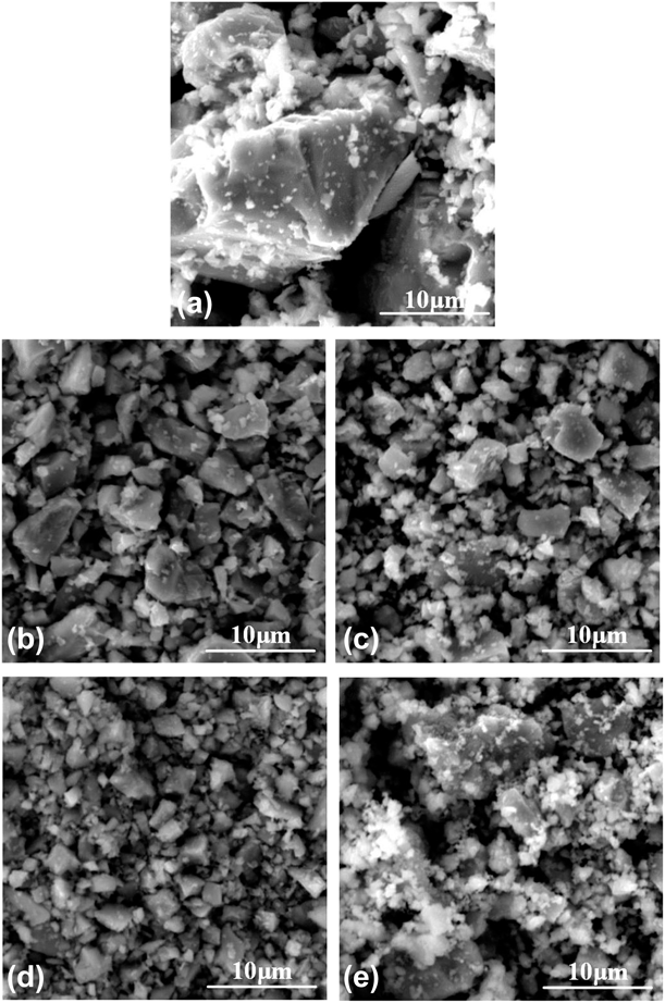
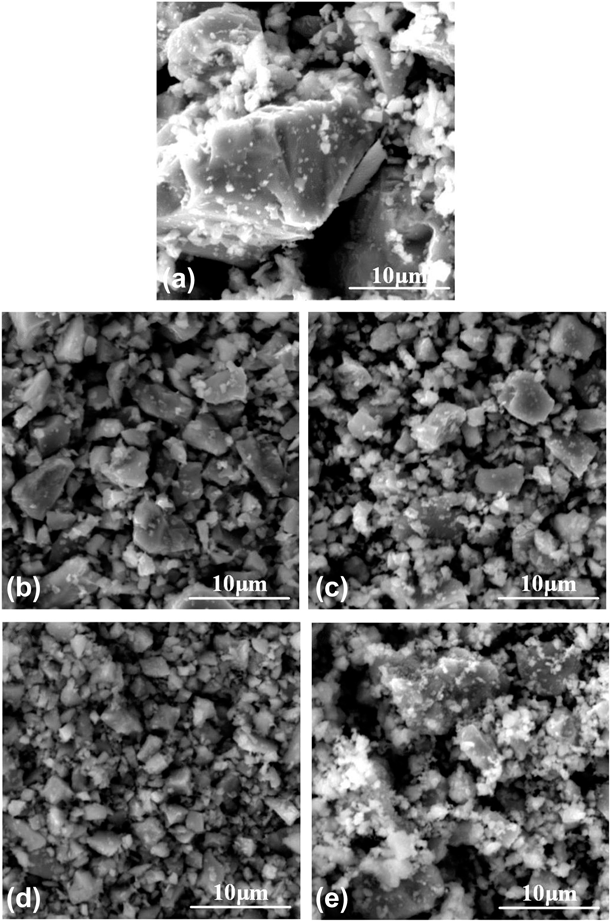
Figure 1 shows the morphology of the powders before and after milling for different times. It is clear to see that the particle size decreased gradually with increasing milling time. When milled for 2 h, as seen in Fig. 1(e), fine particles began to agglomerate; this is because that during milling process, the particles were refined gradually and their specific surface area increased; these new internal and external surfaces store high energies, which can lead to the spontaneous agglomeration of the fine particles.
SEM images of the milling powders: (a) 0 h, (b) 0.5 h, (c) 1 h, (d) 1.5 h, and (e) 2 h.
X-ray diffraction analysis
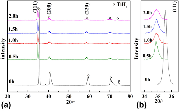
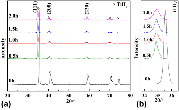
Figure 2 shows the X-ray diffraction (XRD) patterns of the powders milled for different times. After ball milling, except for TiH2, no new peak appeared, which indicates that no new phase was formed. However, the peaks after ball milling, all shifted to a lower angle, which could be seen clearly in the enlarged view for (111) peak [Fig. 2(b)]. This phenomenon indicates that the lattice parameter of powders increased after ball milling. In this experiment, under high pressure and mechanical force, N was easy to adsorb and solute into TiH2; thus, the increase in lattice parameter should be due to the adsorption and solution of N.
XRD patterns of powders milled for different times: (a) XRD of powders and (b) enlarged view of (111) peak.
Characterization of the composites sintered
Phase identification
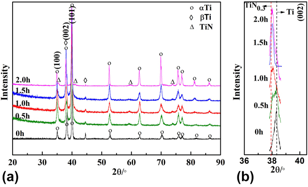
Figure 3 shows the XRD patterns of the sintered TiN/Ti composites. αTi, βTi, and TiN were detected. As the TiN was fine in the nano-sized scale and its content was small, only minor TiN phase was shown to be present. In addition, similar to the XRD patterns of milling powders in Fig. 2, compared with matrix Ti, the peak of sintered composites all exist at lower angles, and the peak decreased in angle with the increase in pretreatment milling time, which can be seen clearly in Fig. 3(b) for the (002) peak.
XRD patterns of sintered composites: (a) XRD of composites and (b) enlarged view of (002) peak.
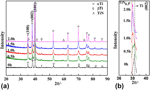
As shown in Ti–N binary diagram in Refs. Reference Hilmar and Vladimir[42 and Reference Ohtani and Hillert43], when the percent of N is less than 30 at.%, N solutes into Ti, and when it exceeds 30 at.%, TiN can be formed. Thus, the formation of TiN is a process in which N solutes into Ti first and when the percent of N exceeds 30 at.%, TiN precipitated, which have also been proved in our previous study [Reference Li, Lv, Chen, Liu and Bai44]. In fact, TiN0.3 peak is at the position of red line as shown in Fig. 3(b). The experimental peaks approach to TiN0.3 gradually, with an increase in milling time, which also indicates that before formation and precipitation of TiN, N solubilized into matrix Ti and resulted in the shift of the peak.
During sintering process, under high temperature, H evaporated from TiH2, and N and Ti reacted to form TiN. The formation of TiN is controlled by the diffusion of N2 into Ti particle. Only when the percent of N exceeds 30 at.%, TiN can be formed.
Microstructure
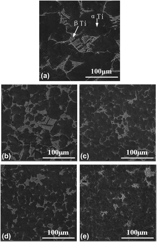
Figure 4 shows the microstructures of pure Ti and the sintered composites. The composites were homogeneous and compact, and no obvious pores or cracks were found. The matrix was composed of αTi and βTi. From the scanning electron microscopy (SEM) results, no TiN phases were directly found, which may be due to the limited magnification of the nano-size reinforcement with SEM.
SEM images of sintered composites: (a) 0 h, (b) 0.5 h, (c) 1 h, (d) 1.5 h, and (e) 2 h.
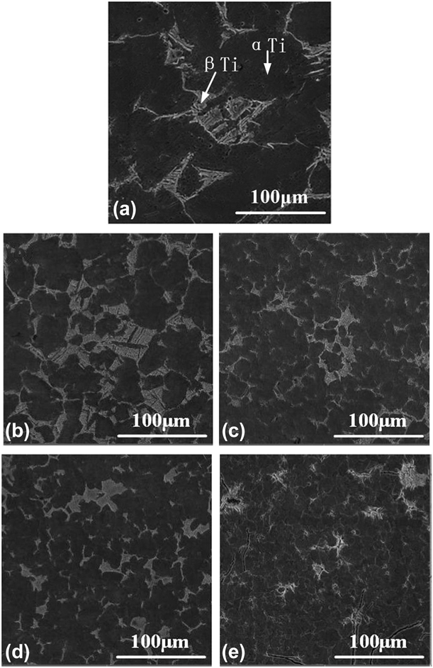
In addition, it is clear to see that the grain size was refined with increasing pretreatment ball milling time. On the one hand, with the increase in pretreatment ball milling time, the particle size of powders decreased gradually and the grain size of sintered composites was refined accordingly. On the other hand, the increase in the content of TiN particles can provide some heterogeneous nucleation sites during solidification, which can also result in a more refined microstructure.
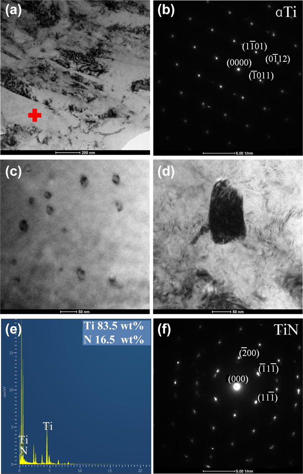
To confirm the presence of TiN and characterize the microstructures of the samples, we performed transmission electron microscopy (TEM) analysis. Figure 5(a) shows the matrix, and the diffraction patterns in Fig. 5(b) imply that the lath-shaped phase was of αTi in a hexagonal close-packed structure. Figures 5(c) and 5(d) show the typical TiN with a particle size of 20–100 nm. The energy-dispersive X-ray spectrometer (EDS) analysis indicates that the atomic ratio of Ti:N was approximately 1:0.68. The diffraction pattern of TiN in Fig. 5(d) is presented in Fig. 5(f).
TEM analysis of the sintered composites milled for 1 h: (a) TEM micrograph of composite, (b) corresponding Selected-area diffraction (SAD) pattern of αTi, (c) and (d) nanoparticle of TiN, (e) EDS of (d) TiN, and (f) SAD pattern of (d) TiN.

Mechanical properties
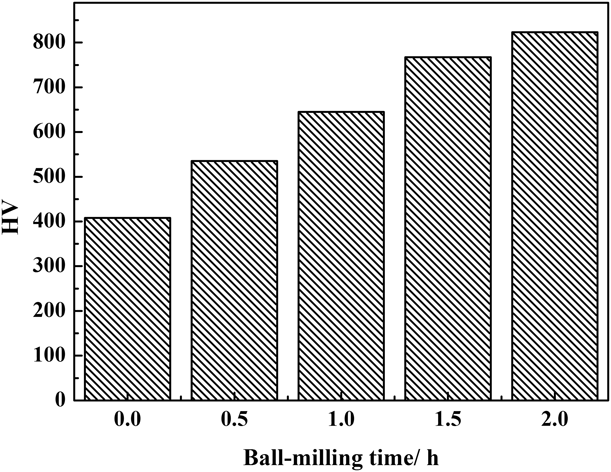
The mechanical properties were evaluated by hardness and compressive tests. Figure 6 shows the hardness of pure Ti and the sintered composites (the results are an average of 5 points). Compared with the samples without pretreatment, the hardness is increased by 31, 58, 93, and 101% in composites with increase in milling time. The value for pure Ti in this study is a little higher than that in previous studies. The value for pure Ti differs significantly in different studies [Reference Gu, Meng, Li, Wilhelm and Reinhart45, Reference Li46] due to the different preparation methods and experimental conditions. The result in this study is most congruent with that in the study of Li [Reference Li46], with 315 MPa.
Hardness of sintered composites and pure Ti.
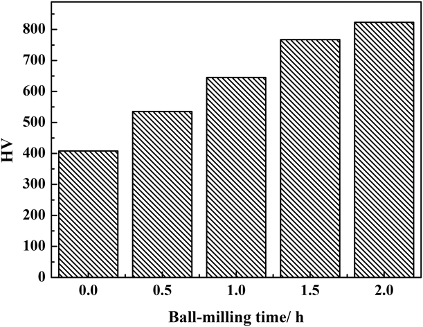
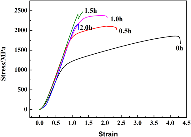
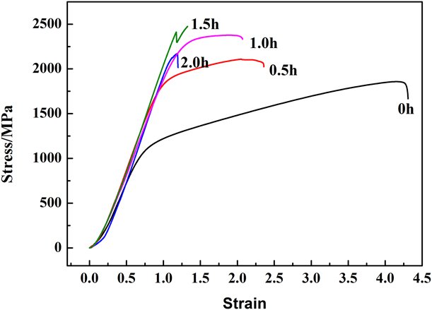
Figure 7 shows the compressive stress–strain curves of pure Ti and the sintered composites (the strength results are an average of 3 samples and the accuracy are within 5 MPa). The corresponding values of the maximum compressive strength are 1795, 2105, 2350, 2440, and 2120 MPa and the ductility are 4.1%, 2.3%, 2.0%, 1.4%, and 1.2%, respectively. The compressive strength of pure Ti differs a lot in several studies due to the different experimental methods and conditions [Reference Yang, Lu, Zhao, Qin and Zhang47, Reference Qu, Zhang, Han, Zhang, Yang and Chen48]. However, the compressive stress–strain curves of pure Ti and the sintered composites all show an upward trend with the addition of reinforcements. In this study, with increasing milling time, the compressive strength of the sintered composites increased initially but later decreased when milled for 1.5 h, that is, the compressive strength increased to a maximum value of 2440 MPa and then decreased slightly to 2120 MPa. Within a certain range, the strength of composites can be enhanced significantly by increasing the reinforcements. However, excess amount of reinforcements can lead to increased brittleness and reduce the strength of composites. Similar phenomena have also been reported in Refs. [Reference Jin, Wang, Gao, Qiao and Jin13, Reference Lagos, Agote, Atxaga, Adarraga and Pambaguian15, and Reference Qi, Wang, Zou and Wei16]. Moreover, when compared with pure Ti, the ductility of the composites decreased gradually with increasing milling times, which means that the plasticity and toughness decreased, whereas the hardness and strength increased.
Compressive stress–strain curves of the sintered composites and pure Ti.
Mechanism of reinforcement
Several explanations for the reinforcement mechanism of MMCs, such as second phase, solution, refinement, Orowan, load transfer, and dispersion strengthening, are present. The reinforcement mechanism involved in the preparation of composites usually depends on the preparation method and the formation process of the reinforcements. During the preparation of composites, reinforcement may not be controlled by only one mechanism but also by several mechanisms working together.
In this study, though the phase content can be calculated through XRD pattern, the content of TiN is hard to calculate, because the TiN peak is minor and hard to separate from Ti peak when fitting the peaks. However, other studies [Reference Zhou, Qiu and Jiang6, Reference Romero, Amigó, Salvador and Martinez49], in which TiN was added directly to matrix, have shown that only small amount TiN of 1 wt% can increase yield strength by 20% and hardness by 50%.
Except for TiN reinforcements, as shown in Fig. 3, the peaks of composites all shifted to a lower angle compared with pure Ti, which suggests that the additive N atoms were dissolved into the crystal lattice Ti and the interstitial solid solution of heteroatoms was formed. The effect of N solution on composites can be seen in Ref. [Reference Mimoto, Umeda and Kondoh50]: only 0.74 wt% of N can increase the tensile strength of pure Ti by 82%. In this study, the content of N was in large amounts of approximately 30 at.% (∼10 wt%), which must show a significant effect on the Ti matrix.
In addition, from Fig. 4, it is clear to see that the grain size was refined with increasing pretreatment ball milling time, which can also increase the mechanical properties of composites. In fact, the yield strength follows the well-known Hall–Petch relationship [Reference Hansen51]:
 $${\sigma _{\rm{y}}} = {\sigma _0} + k{d^{{1 / 2}}}\quad ,$$
where σy is the yield strength, σ0 is the lattice friction stress, k is a constant, and d is the grain size. According to Ref. [Reference Ahn, Chun, Yu, Kim and Hwang52], σ0 = 273 MPa and k = 0.27 MPa m1/2. The grain size d can be calculated from Fig. 3 according to the Scherrer formula:
 $$d = {{K\lambda } \over {B\cos \;\theta }}\quad ,$$
where d (nm) is grain diameter, K is a fixed constant (0.9), λ (nm) is wavelength of X-rays (0.15406), B is the half-width of peak (in radians), and θ° is diffraction angle.
Taking peak (101) for calculation, the calculated grain size d and yield strength σy are shown in Table I. The refined grain size can increase the yield strength of composites by about 30% compared with pure Ti.
The calculated grain size and yield strength of sintered samples.

All the TiN reinforcements, N atom solution, and refined grain size contributed to the reinforcement of composites. N atom solution contributed the most, while TiN reinforcements and refined grain size also improved the mechanical properties of composites.
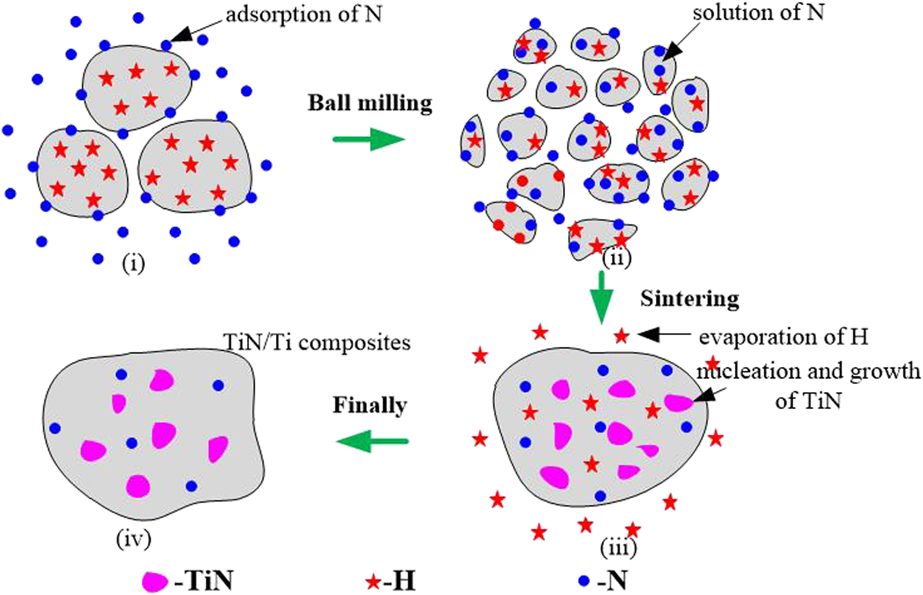
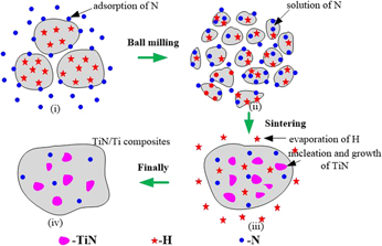
Figure 8 demonstrates a reasonable mechanism for the formation of TiN-reinforced Ti matrix composites by a high-energy ball milling pretreatment and a subsequent hot-press sintering treatment.
(i) At the initial stage of milling, N2 was absorbed on the surface of powders;
(ii) With increasing milling time, the particles were refined gradually, and under continuous mechanical force, N2 diffused into TiH2 particles;
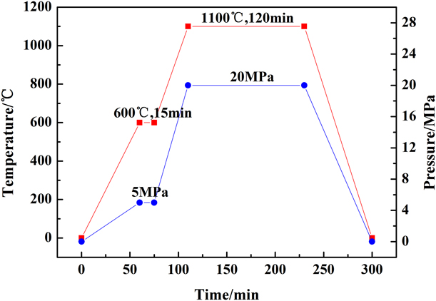
(iii) During sintering process, H evaporated from TiH2 particle, and the dehydrogenation temperature of TiH2 was not more than 600 °C, and with the increase in milling time, the dehydrogenation temperature of TiH2 decreased gradually [Reference Cao, Xiao, Lei, Zhang, Fan and Xuan53, Reference Zhang, Yi, Gan, Yan, Du and Liu54]. In this experiment, at 600 °C and 1100 °C, TiH2 were kept for 15 and 120 min to ensure that H evaporated from TiH2, respectively. Under high temperature, the lattice was restructured, and the solution N reacted with Ti to form TiN. The formation of TiN was a process of solution of N, followed by the precipitation of TiN, which has been demonstrated by Ding et al. [Reference Ding, Yao, Qiu, Bai, Guo, Xue, Wang, Zhou and Su55]. Thus, when the amount of N exceeds a certain percentage, it forms TiN. In this experiment, except for TiN, some N solubilized into matrix were present.
(iv) Finally, TiN/Ti composites were obtained with solution N in matrix.
Schematic of formation mechanism of TiN/Ti composites.

Conclusions
(1) During milling process, N2 was absorbed and solubilized into TiH2, and the TiN were formed during sintering process and is fine to a grain size of 20–100 nm.
(2) When compared with pure Ti, after milling for 0.5, 1.0, 1.5, and 2.0 h, the hardness of composites increased by 31%, 58%, 93%, and 101%, respectively. The compressive strength initially increased and later decreased to 2440 and 2120 MPa when milled for 1.5 h, respectively.
(3) The reinforcement mechanism of TiN/Ti composites was contributed to the (i) solution of N in the matrix, (ii) formation of nano-sized TiN, and (iii) refinement of the grain size by ball milling.
Experimental procedures
The raw materials used were TiH2 powders (99.8% purity, 44 μm) and N2 (99.99% purity). For the ball milling pretreatment, TiH2 powders were milled in a N2 atmosphere under a pressure of 4 × 10⁵ Pa in a high-energy ball milling machine (PM100; Retsch, Haan, Germany). The weight ratio of ball-to-powder was 15:1, rotation speed was 200 rpm, and the milling time were 0.5, 1.0, 1.5, and 2 h. An intermittent ball milling pattern, that is, 0.5 h of ball milling, followed by a 10-min interval, was adopted to avoid excessive temperature rise within the grinding bowl.
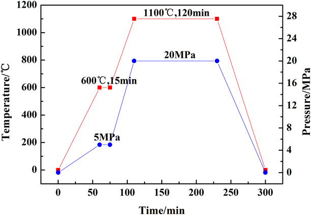
The prepared powders were then sintered in a hot-press sintering furnace (HZK-25) with a maximum vacuum, temperature, and pressure of 1.33 × 10⁻³ Pa, 2000 °C, and 15 t, respectively. The die cavity diameter was 50 mm. The powders were first heated to 600 °C at a heating rate of 10 °C/min and kept for 15 min to decompose TiH2. The powder was then heated to 1100 °C with heating rate of 10 °C/min and maintained for 2 h for sufficient sintering. Simultaneously, a pressure of 20 MPa was applied. The time-dependent temperature and pressure profiles of the hot-press sintering process are shown in Fig. 9.
Temperature and pressure profiles with time for the hot-press sintering process.
The milled powders and sintered samples were characterized by XRD using D/max-rB (Rigaku Co., Tokyo, Japan) with a voltage 40 kV, current 50 mA, scanning speed 10°/min, and scanning angle 10°–90° by Cu Kα radiation (λ = 0.15406 nm). The morphology of the powders and the microstructures of the composites were examined by SEM (TESCAN VEGA 3 LMH, Tescan, Brno, Czech Republic) and TEM (FEI TECNAI G2 F20, FEI Nano Ports, Hillsboro, Oregon). For SEM observations, the samples were first etched with HF + HNO3 + H2O. The TEM foils were prepared using the ion beam thinning technique (GATAN 691, Gatan, Pleasanton); before ion milling, the foils were first dimpled to 10 μm on an ultra-precision dimpling grinder (FISCHIONE 200, Fischione Instruments, Pennsylvania). The hardness test was performed on a Vickers hardness tester (HV200, Chang Taylor Instrument, Jiangsu, China), and the compressive test was performed on a universal testing machine (Instron 5569, Instron Corporation, Boston, Massachusetts) at room temperature with a strain rate of 0.5 mm/min. The specimen size was 5 × 5 × 20 mm.
Acknowledgment
This work was funded by the State Key Laboratory of Mechanical Transmission, Chongqing University, Chongqing, China, No. SKLMT-ZZKT-2017Z08.