I. INTRODUCTION
The thermal protection system (TPS) is a barrier that shields the heat produced by the friction of the atmospheric gasses against the outer surface of a space vehicle during the atmospheric entry. Since vehicle speed is hypersonic, gasses immediately turn into a superheated plasma causing high thermo-chemical loadsReference Gnoffo1,Reference Bertin and Cummings2 around the spaceship surface which must be protected by engineered materials. TPS can be grouped into two categories.Reference Johnson3 The first is the reusable TPS (RTPS). RTPS are adopted for relatively low temperatures (∼1000 °C), when gas velocity and density are low; they account on the low thermal conductivity, reflectivity, and opacity of their constituent materials. The second, named ablative TPS (ATPS), dissipates the incoming heat with endothermic chemical reactions of its polymer matrix constituent material. ATPS are adopted when gas velocity, density, and thus temperatures are extremely high. The concept proposed in this paper falls within RTPSs.
Beside the above mentioned thermal requirements, TPSs should comply with other design and operational constraints: structure smoothness (to avoid stress concentrations), low areal weight, low costs, low maintenance, mechanical, and thermal compatibility with the primary aluminum structure.
The space shuttle orbiter gave a great impulse to the RTPS development. To protect its aluminum alloy airframe, four types of RTPS have been used: a structural carbon-carbon material; a high-temperature reusable surface insulation (HRSI); a low-temperature reusable surface insulation (LRSI); and felt reusable surface insulation (FRSI). Advantages and drawbacks of these materials are extensively discussed by Hurwitz in his book chapter.Reference Hurwitz4
Similarly to FRSI, fibrous refractory composite insulations (FRCI) TPS were designed mainly with thermal insulating functions; their damage tolerance is thus relatively low. They are comprised of short oxide fibers (Quartz, Allumina, Mullite), which are first cold pressed and then consolidated by sintering with a second phase (usually oxide micro/nano powders). As a drawback, FRCI requires waterproofing while the vehicle is on the ground, making their maintenance rather expensive.
Following the space shuttle experience, extensive research work in the USAReference Scotti, Clay and Rezin5 and EuropeReference Glass6–Reference Fischer8 has been carried out. Many RTPS concepts have been developed at different technology readiness levels (TRL). The principal objective of these new RTPSs is their multi functionality: they must be at the same time high thermal insulating systems and load bearing structures. RTPSs pursue two strategies to dissipate heat: by passive or active cooling. We will focus on passive cooled solutions that need a great effort in materials development, due to the high temperatures involved.
New tile and blanket conceptsReference Myers, Martin and Blosser9 have been developed over the last years. Structurally integrated TPS,Reference Fischer8,Reference Pichon, Barreteau, Soyris, Foucault, Parenteau, Prel and Guedron10 multilayered insulations,Reference Glass6 an open-cell foam skeleton filled with ultralow-density carbon aero gels.Reference Dadd, Owen, Hodges and Atkinson11
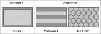
Based on their 2-fold function (thermal and structural), these RTPSs can be gathered in two categories (see Fig. 1) those with an outside load bearing structure (i.e., exoskeleton) or with an embedded reinforcement (i.e., endoskeleton).
Reusable TPS concepts with an external primary load bearing structure,Reference Pichon, Barreteau, Soyris, Foucault, Parenteau, Prel and Guedron10 a multi layered solution,Reference Glass6 and a filled reticulated ceramic.Reference Dadd, Owen, Hodges and Atkinson11

In the last configuration of Fig. 1 the endoskeleton is realized with a macroporous reticulated ceramic (MRC). These ceramics are characterized by large pores and relatively high mechanical propertiesReference Studart, Gonzenbach, Tervoort and Gauckler12 even after the onset of crack growth.Reference Brezny and Green13–Reference Ortona, D’Angelo and Bianchi16 Reticulated ceramics are a category of the so called hybrid materialsReference Ashby17 whose properties, in the case of lattice structures, can be engineered.Reference Ortona, D'Angelo, Gianella and Gaia18 In this work we realized a heteroporous heterogeneous ceramic (HHC) by combining a SiSiC MRC with a FRCI made of packed short oxide fibers with smaller pore sizes. SiSiC MRC are characterized by high thermo-mechanical properties,Reference Ortona, Pusterla, Fino, Mach, Delgado and Biamino19 low density, low relative thermal conductivity, but, because of their high porosity and large pore size, they are mostly transparent to radiation. FRCI are highly thermally insulating and, because of their smaller pore size, opaque to radiation. On the other hand, being made of short, nonconnected fibers, FRCI are not able to carry loads.
HHC tiles can be in turn integrated into a sandwich structured CMC structure as already done with SiSiC MRC cores.Reference Ortona, Pusterla and Gianella15,Reference Hurwitz20
Further research work, carried on within the European FP7 project: Multifunctional Components for Aggressive Environments in Space Applications (SMARTEES), aims at integrating these structures within a multilayered reusable thermal protection system.
II. EXPERIMENTAL
A. Materials
ERBISIC-R foams (Erbicol SA, Balerna, Switzerland), produced by the replica methodReference Schwartzwalder, Somers and Somers21 followed by liquid silicon infiltrationReference Adler, Graeber, Standke, Jaunich, Stoever and Stoetzel22 were used as MRC. Their skeleton is comprised of α and β SiC grains dispersed in a silicon matrix (∼20 vol%) as a result of the liquid silicon infiltration. The SiSiC scaffold density is 2.83 ± 0.07 (g/cm3) with no residual porosity. The elastic modulus of the SiSiC skeleton is 264 ± 9 (GPa) and the modulus of rupture (M.O.R) is 203 ± 13 (MPa) (Erbicol database). SiSiC thermal conductivity and coefficient of thermal expansion at ambient temperature are respectively 7 × 10⁻⁶ (K−1) and 85 ± 3 (W/m/K).
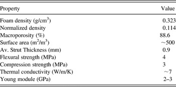
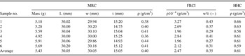
Morphologically, these foams are an isotropic three dimensional arrangement of hollow ceramic tapered ligaments. The main properties of foams are presented in Table I. Due to the specific foaming process used to produce the polymeric template,Reference Mills23 the cells of the SiSiC foams produced by replica are mostly elongated in one direction, frequently called the rise direction. This elongation imposes an anisotropic mechanicalReference Sullivan, Ghosn and Lerch24–Reference D’Angelo, Ortona and Colombo26 and thermalReference Pusterla, Ortona, D’Angelo and Barbato27 behavior to the foams.
SiC foam properties (ERBISIC-R foam, 10 PPI, source: Erbicol SA).

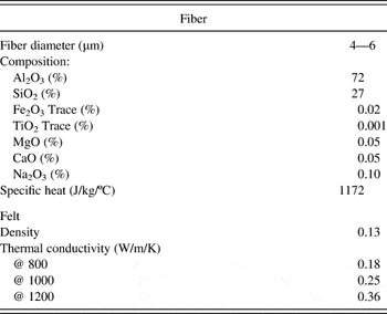
As a second insulating phase Fibermax™ bulk fibers (UNIFRAX Niagara Falls, NY) were utilized. Fibers characteristics are reported in Table II.
Physical properties of the oxide fiber insulating phase (Fibermax®) from product datasheet.

B. Process
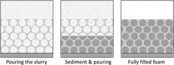
Figure 2 shows the process used to fill the MRC. A dispersion of short fibers was forced to pass through the MRC pores. Fibers were stopped at the bottom of the foam by a filtering medium. A similar procedure was previously adopted to fill with SiC powders a porous CMC perform.Reference Nannetti, Ortona, Pinto and Riccardi28 To obtain the dispersion, 0.06 wt% of the surfactant (Triton X100, SIGMA Aldrich, Saint Louis, MO) was diluted in distilled water, then short oxide fibers (5.7 wt%) were added and dispersed by ball milling for 80 min.
MRC filling via forced sedimentation: fiber dispersion pouring, water draining and fiber sedimentation and further pouring. The procedure was repeated till reaching the complete filling of the MRC body.

The MRC samples were laid on a filter paper and a metallic net (Fig. 2) placed at the bottom of a metallic case surrounding the MRC. The dispersion was then poured into the case and forced to pass by gravity through the SiSiC foam and the filter. The fibers, stopped by the filter, started to compact from the bottom of the foam (Fig. 2). This forced sedimentation let the FRCI layer grow inside the MRC. The dispersion was poured several times until the entire MRC was filled with short fibers.
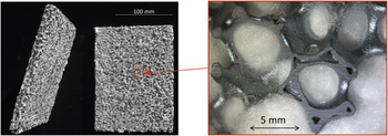
The fibers amount into the dispersion, and the filter pore size were optimized to fill the MRC in situ grown FRCI (Fig. 3). For the following thermal loading tests, six samples were produced, their properties are reported in Table III.
On the left a 120 × 180 (mm) HHC tile produced filling reticulated SiSiC with oxide fibers. On the right a close view of the HHC showing the complete filling of the macroporosity.

MRC, FRCI and HCC weights volumes and related properties before and after the forced sedimentation process.

C. Thermal loading
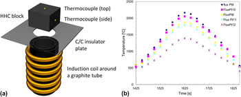
Thermal loading was executed in a vacuum chamber (10−4 mbar) equipped with an inductively heated blackbody radiator [Fig. 4(a)]. Thermal load profiles were derived from the ARV re-entry simulation data.Reference Scheer, Tran and Berthe29 The heat fluxes as a function of time were converted into the blackbody radiator temperatures as per Fig. 4(b). Thermal loadings were repeated 3 times for each thermal profile. The black body radiator temperature was monitored with an optical pyrometer.
(a) Black body radiator consisting in a graphite tube heated by induction. (b) Black body radiator heating profiles inferred from the ARV mission.

The faces of the HHC block not in direct contact with the blackbody radiator were wrapped with an oxide based insulating material to prevent stray heat fluxes. HHC temperatures on the top and aside [Fig. 4(a)] were recorded with two 1.5 mm diameter type K thermocouples coated with Inconel™ (Special Metals Corporation, Huntington, WV). The very temperature on the HHC surface facing the radiation emitter was not recorded because of the high temperatures involved.
D. Characterization
Microstructure evaluations were performed with an optical microscope (Leica DMLM, Wetzlar, Germany) and Field Emission Scanning Electron Microscope (FESEM Supra 25 D, Zeiss, Oberkochen, Germany). The micrographs were taken in backscattered electrons (BSE) mode to enhance the contrast between each phase. An Energy-dispersive x-ray spectroscopy (EDS or EDX) analysis on the ligaments surface was performed to retrieve the elements. From sample 1, MRC and FRCI were separated and brought to powder with a mortar. XRD analysis was then performed with x-ray generator system (PW 3830, Philips, Eindhoven, Netherlands).
III. RESULTS AND DISCUSSION
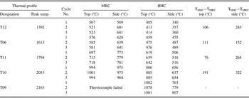
The peak temperatures recorded for each cycle are reported in Table IV. They clearly show that the temperature on the top of the foam is significantly reduced by the HHC system in respect of the MRC. This is the evidence that the heat transfer by radiation was consistently lowered. Table III reports the maximum temperature gradients between the top of the HHC and the heat radiator. The last two columns of Table IV show how HHC shielding efficiency was improved in respect of the MRC. In particular, for temperatures up to 2000 °C, the HHC has an average insulating capability that is 20% higher than the MRCI along the HCC thickness. The insulating capability rises to 35% for temperatures measured on the side. This direction dependant heat transfer is more considerable in HHC where the radiative contribution was restricted by the FRCI. If heat flows mainly by conduction, the difference may be explained by the morphological anisotropicity of the MRC, as extensively discussed elsewhere.Reference Pusterla, Ortona, D’Angelo and Barbato27
Temperature acquisitions on MRC and HHC foams measured on top and aside the HHC block and their mean difference in °C. Blackbody radiator temperature was measured with an optical pyrometer.

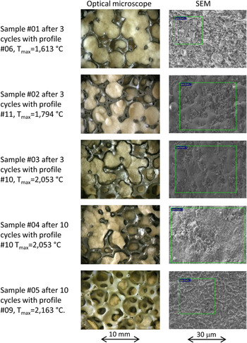
A close view at the HHC material reveals its behavior after the different thermal cycles.
In the first row of Fig. 5 the filler material is unaffected by the heat fluxes applied. The strut surface is rough and all the elements contained in the filler are detected on it. In the second row of Fig. 5 the FRCI appears still unchanged, but the surface of the struts is smoothened by silicon melting.
Different HHC samples after thermal loading profiles no. 06, 11, 10, 09. Left column, macroscopic view of the foams after thermal loading. Right column, SEM images of the strut surface with the area where EDS analysis was performed.

The strut surface exposed to the two most severe thermal loadings, with peak temperatures of 2053 and 2163 °C (fourth and fifth rows of Fig. 5) is flat with white features.
From the fifth row of Fig. 5 it is also evident that HHC shielding efficiency was reduced because of the filler recession, probably due to a sort of sintering effect coupled with oxides volatilization. The SiC scaffold looks macroscopically unaffected although its surface was clearly melted.
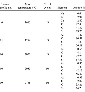
The element analysis was first performed on areas comprising several foam cells filled by the ceramic fibers. The elements constituting the foam (Si and C) and the fibers (Si, Al, O and impurities of Ca, Na and Mg) were always detected. On the other hand, when the analysis was repeated separately on MRC (Table V) and FRCI, the results were found to change appreciably depending on the ratio between the amounts of Si-SiC and fibers that can locally change as well. In addition, an excess of Si or C with respect to the SiC stoichiometry was observed at different points of the strut surface since the reactive infiltration with molten silicon not always resulted in the complete conversion of carbon to silicon carbide.
Atomic % of the elements detected by EDS analysis. The area of interest is delimited by the green rectangles in Fig. 5.

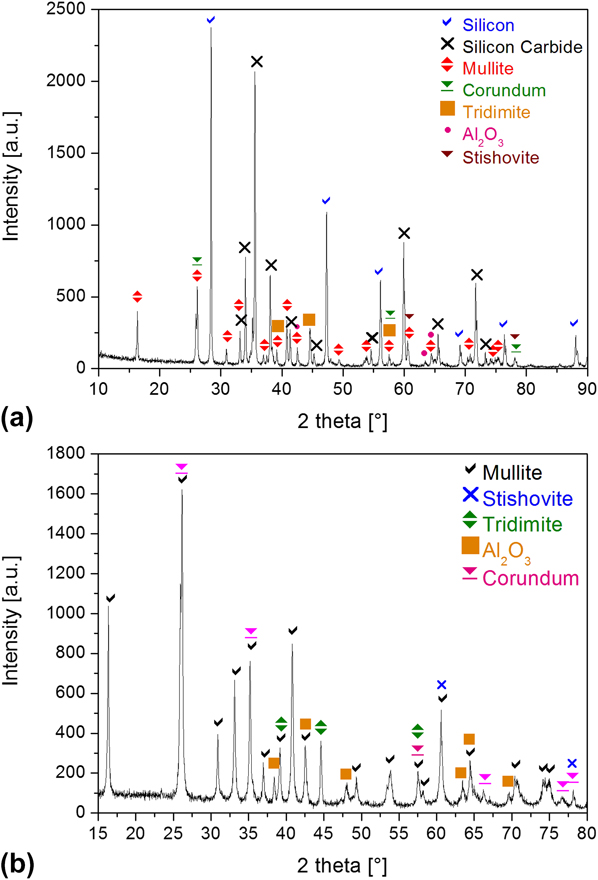
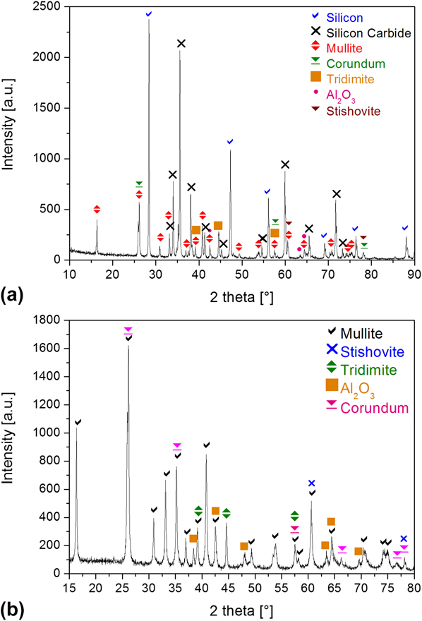
According to XRD analysis the as-produced HHC samples show a complex composition. Silicon carbide and silicon result from the MRC [Fig. 6(a)], with inevitable contaminations of the filler. FRCI consists of mullite, alumina, and silica [Fig. 6(b)]. Most of these components are expected to have melted at the testing temperatures. In particular, silicon melts at 1410 °C, silica at 1723 °C, mullite at 1850 °C and, in addition, the eutectic between silica and mullite melts at 1595 °C. Then, at the test temperatures around 2000 °C most of the filler and silicon turned into liquid phases. Since the vapor pressure of these liquid phases is not negligible,Reference Desai30 they also underwent volatilization during thermal cycling in vacuum. For instance the volatilization rate under vacuum of molten silicon was found as high as 1.3 mg/cm2 min. at 1550 °C and it increases more and more with the temperature.Reference Wei, Ma, Yang, Liu, Dai and Morita31 Also mullite is not stable at temperatures above 1900 °C since it decomposes into alumina and gaseous silica.Reference Xiao and Mitchell32 Then the depletion of the filler that has been observed after cycling the specimens at the higher temperatures (Fig. 5) is to be attributed to the volatilization of alumina and silica. The EDS results (Table V) clearly show that the content of Al and O progressively decreases with the increase of the maximum temperature experienced by the specimens during the thermal cycling and then with the importance of the volatilization of the oxides. Also silicon should evaporate in these conditions and thus foam weight losses might be expected. Finally the gaseous silica can react with the SiC scaffold according to the reaction:
 $${\rm{SiC}}_{{\rm{(s)}}} + 2{\rm{SiO}}_{{\rm{2(g)}}} \to 3{\rm{SiO}}_{{\rm{(g)}}} + {\rm{CO}}_{{\rm{(g)}}\quad} .$$
XRD spectra on the as-produced HHC sample no. 1: (a) the MRC skeleton and (b) of the FRCI.
This reaction of active oxidation is believed to gain importance with the temperature increase and when the oxygen partial pressure is very low, i.e., the vacuum of the actual thermal cycling test.Reference Jacobson and Myers33
IV. CONCLUSIONS
This paper presents a novel fabrication procedure of light structural thermal protection systems comprised of a load bearing structure made of a macroporous reticulated ceramic with high relative thermo-mechanical properties filled with compacted short oxide fibers. The process is very simple and does not require special devices or ambient conditioning. The produced heteroporous heterogeneous ceramics were tested under thermal cycling conditions similar to the re-entry of the ARV capsule. Results show high radiation shielding capabilities, with substantial material resistance up to very high temperatures. Even after repeated exposures at extremely high temperatures, the material degradation seems to be not so significant for temperatures of the black body radiator below 2000 °C. Beyond this temperature the FRI phase experienced a progressive degradation mainly due to mullite and alumina volatilization. Further work is ongoing to characterize these new materials and to integrate them into a complete TPS system.
ACKNOWLEDGMENT
The research leading to these results has received funding from the European Union Seventh Framework Program (FP7/2007–2013) under grant agreement no 262749 (Project SMARTEES).