Introduction
Due to the increasing growth in mobile users, smartphones and internet of things connections as well as network speed improvements and cellular video consumption are projected to increase the data traffic by seven times over the next 5 years. It is expected that by the year 2021, the number of mobile phones (5.5 billion) will be higher than bank accounts (5.4 billion) or landlines (2.9 billion). The bandwidth-hungry video will farther increase the demands on mobile networks, accounting for 78% of mobile traffic [1]. To overcome these challenges and to achieve an ultra-fast transmission rate (peak data rate ≥10 Gbps), small latency (≤1 ms), extremely high traffic volume density (≥106/km2), super-dense connections and higher mobility (≥500 km/h), the 5G mobile communication system is deployed in the third quarter of 2019 [Reference Agiwal, Roy and Saxena2]. It is estimated that 5G mobile connections will increase from just 5 million in 2019 to 577 million by 2023 [3]. It is expected that while operating over a wide range of frequencies, the new 5G radio access networks will simultaneously support numbers of connections. To enable the 5G, FCC divided the key spectrum into low-band (up to 1 GHz), mid-band (sub-6 GHz), and high-band (mmWave) [Reference Marcus4,Reference Rappaport, Sun, Mayzus, Zhao, Azar, Wang, Wong, Schulz, Samimi and Gutierrez5]. The mmWave offer lightning-fast data rates above 2 Gbps and huge capacity, while low-band offers good 5G coverage and mid-band offer a blend of both. It is clear that to attain the target of ultra-fast data rates, the use of 5G mmWave spectrum is desirable. However, some crucial challenges must be fulfilled before the implementation of mmWave mobile communications. Before the finalization of mmWave technology for 5G communications, sub-6 GHz is the go-to 5G technology in the near term. As the sub-6 GHz 5G communication can send high data rates over long distances, it is suitable to be used in both urban and rural areas. In sub-6 GHz band, UK has already auctioned 3.4–3.6 GHz band for commercial uses and in the first quarter of 2020 they have a plan to adopt 3.6–3.8 GHz band. In the mid-band, Italy, Spain, Romania and Hungary have already deployed the 3.6–3.8 GHz band, France has started using 3.46–3.8 GHz band, Switzerland, Greece, Sweden, Finland and Ireland have started using 3.4–3.8 GHz band, and Germany has started using 3.4–3.7 GHz band. In China, MIIT has allocated 3.3–3.6 GHz and 4.8–5.0 GHz as official 5G bands. In sub-6 GHz band, South Korea started the use of 3.42–3.7 GHz band and achieved 3 million users as of September 2019. Japan issued the license to 3.6–4.2 GHz and 4.4–4.9 GHz bands for commercial use of sub-6 GHz 5G bands. Australia has started the use of 3.4–3.7 GHz as lower 5G band while New Zealand is using 3.4–3.59 GHz as initial 5G band. The USA has already deployed 3.5 GHz band as 5G band [6].
Antennae are an integral part of all mobile communication systems. As the world ha already embraced the 5G communication system, antenna design for 5G base stations and mobile phones is therefore in great demand. For civil, military, satellite, and underwater application, the 5G antenna should be operable at wide/multiple frequency bands and robust. Due to the variation of the frequency spectrum, antenna designing for 5G communication system faces enormous challenges. The antenna for 5G should be compact enough to be embedded in portable devices. Moreover, as the sub-6 GHz antennae have to work along with the existing long term evolution (LTE) and other service band antennae, the 5G antenna should cover the sub-6 GHz bands as well as the existing WiMAX, WLAN, and LTE bands. Among different types of antennae, microstrip patch antenna has become the appropriate choice due to their attractive features of low-profile, lightweight, inexpensive, easy of integration within microwave integrated circuit (MIC)s or monolithic microwave integrated circuit (MMIC)s.
Good numbers of antennae have already been proposed for 5G communication applications. For example, a planar antenna for sub-6 GHz 5G mobile terminal was studied in [Reference An and He7]. The designed antenna comprises a driven strip and three ground strips and is able to achieve −6 dB impedance bandwidth of 0.7–0.96 GHz and 1.6–5.5 GHz. But it requires a big ground plane of 135 × 80 mm2. For LTE-R and 5G mid-band, in [Reference Arya, Kim and Kim8], an ellipse-shaped patch antenna was reported. With an overall size of 180 × 60 mm2, the designed antenna was able to operate over dual bands of 0.66–0.79 GHz and 3.28–3.78 GHz. For 5G communication application, in [Reference Sun, Li and Xia9] a dual-polarized magneto-electric dipole antenna was presented. The studied antenna comprises four horizontal fishtail-shaped patches and four vertical patches and is shorted to the ground. With an overall size of 150 × 150 × 21 mm3, the designed antenna realized an operating band of 3.05–4.42 GHz. But it does not cover the N79 (4.4–5.0 GHz) band. Moreover, its 3D profile restricts its applications in handheld communication devices. In [Reference Khalifa, Khashan, Badawy and Ibrahim10], a monopole antenna was introduced for 4G/5G applications. The studied single-element antenna attained a −6 dB operating bands of 1.24–2.64 GHz and 3.34–5.0 GHz. But it possesses a large dimension of 150 × 80 mm2 and cannot cover the N79 band. In [Reference Sekeljic, Yao and Hsu11], a planar antenna comprised of branched antennae, T-shaped element, a passive element, and matching stub was presented for 2G/3G/4G/5G sub-6 GHz applications. With a size of 50 × 19.75 mm2 it achieved a −6 dB operating bandwidth of 2.5–4.8 GHz. However, it requires a large system ground plane of 110 × 50 mm2. In [Reference Tang, Jiao, Li, Zong, Yao, Shan, Li, Yue and Gao12], a UWB antenna was presented for lower 5G communication. With an overall size of 80 × 50 mm2, the studied design was able to operate over 2.32–5.24 GHz band. A differential fed frequency reconfigurable antenna for mid 5G applications was reported in [Reference Jin, Deng, Yang, Xu and Liao13]. The designed antenna composed of two substrates and the reconfigurability was achieved by four-pin diodes. With an overall volume of 100 × 100 × 5.7 mm3, the studied antenna attained dual operating bands of 2.37–2.67 GHz and 3.39–3.62 GHz. However, its 3D structure limits its use in handheld devices. Moreover, it does not cover the entire sub-6 GHz 5G band. A rectangular planar antenna for 5G communication application was presented in [Reference Sarade, Ruikar and Bhaldar14]. In this design, a simple rectangular patch is used to achieve an operating band centered at 2.425 GHz. But it possesses a large volumetric size of 114 × 77 × 1.6 mm3. A dipole antenna for 4G/lower 5G base station applications was presented in [Reference Gopal and Thangakalai15]. The single element of the designed antenna comprised of dipole elements and modified balun and occupies an area of 76 × 42 mm2 in FR4 substrate. The studied antenna achieved an operating band from 1.341 to 3.834 GHz and fails to cover the entire mid 5G band. In [Reference An, Li, Fu, Ma, Chen and Feng16], a low-profile microstrip antenna was presented for 5G applications. The main antenna structure comprised two FR4 dielectric layers and achieved an operating band of 2.84−5.17 GHz. However, its 3D structure (63 × 51.2 × 4.5 mm3) limits its applications in handheld devices. In [Reference Li, Zhang, Feng and Iskander17], a folded slot antenna was presented for multiband applications. The reported antenna consists of three slots that are arranged on a square column and is able to achieve triple operating bands of 1.69–2.37 GHz, 2.47–2.72 GHz, and 3.23–4.09 GHz. However, it possesses a 3D profile with a volumetric size of 50 × 10 × 10 mm3. For wideband communications, in [Reference Pan, Li, Zhang and Feng18], a slot loop hybrid antenna was presented. The designed antenna consists of a rectangular loop and a monopole printed on both sides of an FR4 substrate. With an overall size of 57.5 × 45 mm2, the fabricated antenna achieved an impedance band of 1.82–5.68 GHz. In [Reference Saxena, Kanaujia, Dwari, Kumar and Tiwari19], a four-port MIMO antenna was studied for 5G applications. The unit cell of the presented antenna is composed of an arc-shaped ground plane and is printed on a substrate of area 50 × 50 mm2. However, it can cover only a 3.4–3.8 GHz band. In [Reference Ren and Zhao20], a two-band MIMO antenna was reported for the mid 5G wireless applications. In this MIMO system, two-antenna pairs are placed vertically on two sides of the ground plane and achieved dual bands of 3.4–3.6 GHz and 4.8–5.0 GHz. Although many of the reported antennae successfully achieved wide/multiple operating band, they have the demerits of 3D profile, complex structure, and exhibits poor performances. Moreover, some of the proposed designs cover only the fraction of the sub-6 GHz band which necessitate the introduction of antenna that can operate over the entire sub-6 GHz 5G as well as ongoing WiMAX, WLAN, and LTE bands.
In this paper, a low-profile multi-slotted antenna is proposed for LTE/sub-6 GHz applications. The antenna comprises a multi-slotted radiating element and a partial ground plane, featuring a simple design without any lumped elements and 3D structure. The studied design operates over 3.15–5.55 GHz with S 11 ≤−10 dB, thus covering the whole NR77/78/79 bands for the sub-6 GHz 5G communications, WiMAX, WLAN, and LTE bands of 22, 42, 43, and 46.
Antenna design
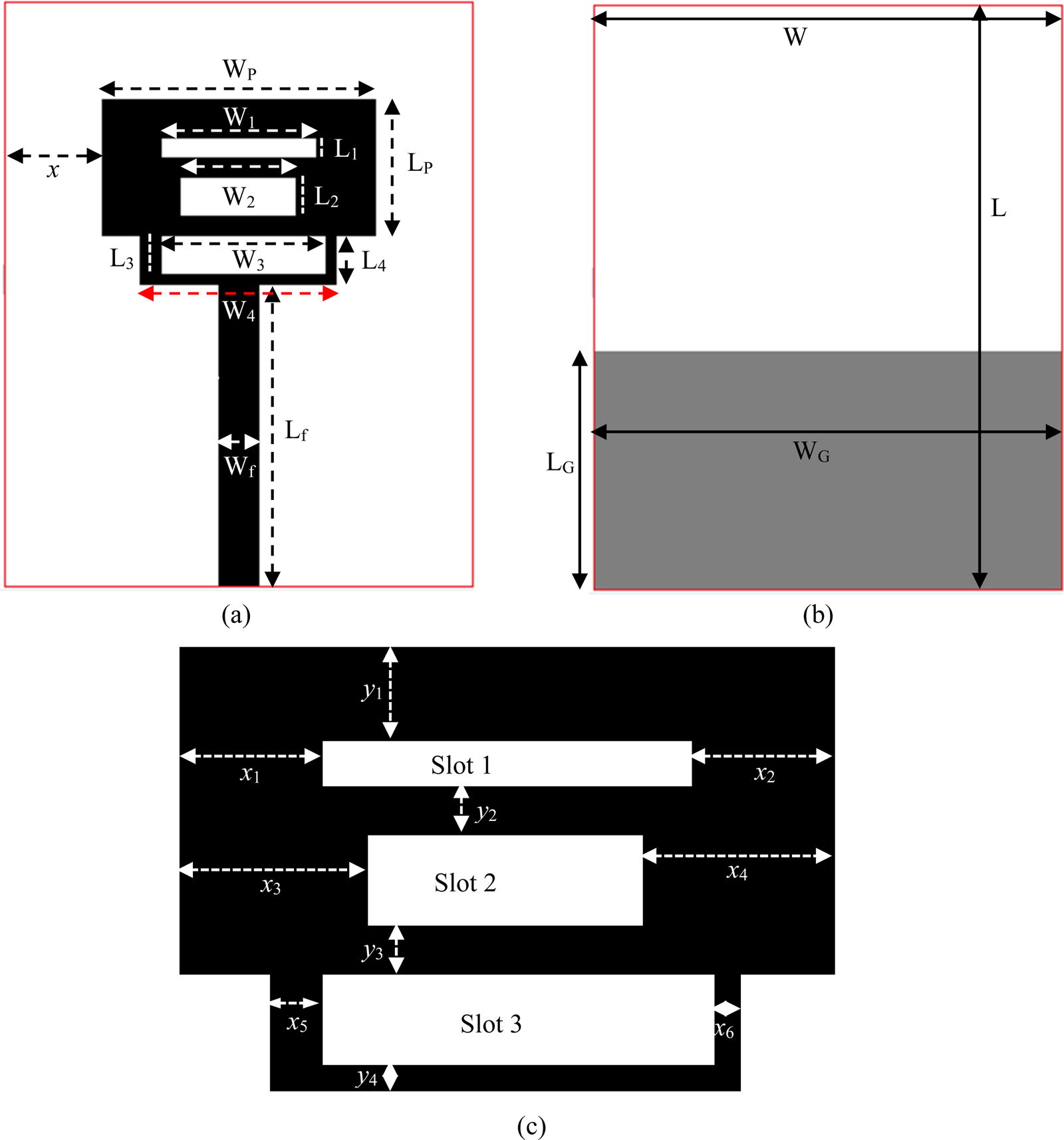
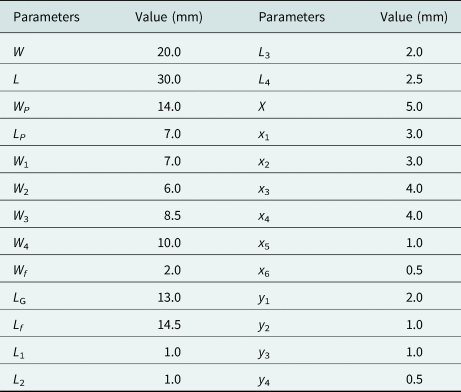
The footprint of the studied multi-slotted antenna is displayed in Fig. 1. The studied design comprises a rectangular steeped radiator and a partial ground plane. The radiation element is etched in the front side of a 1.5 mm-thick FR4 dielectric substrate with permittivity 4.6, loss tangent 0.02 while the ground plane with side length L G is printed in the back side of the double-sided substrate. Three slots of sizes W 1 × L 1, W 2 × L 2 and W 3 × L 3 are symmetrically placed on the patch. To feed the designed antenna, a feedline with 50-ohm characteristics impedance is imprinted along with the patch. A 50-ohm SMA connector is attached at the end of the feedline to excite the studied antenna. To achieve 50-ohm characteristics impedance, the length and width of feedline are respectively fixed at Lf and Wf. The design of the studied antenna is optimized and analyzed using CST Microwave Studio simulator. The detail dimensions of the studied antenna are listed in Table 1.
Antenna topology (a) front view, (b) back view, and (c) multi-slotted patch.

Design parameters of the proposed antenna

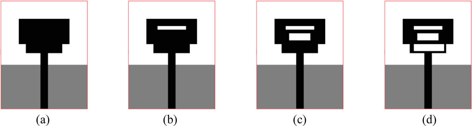
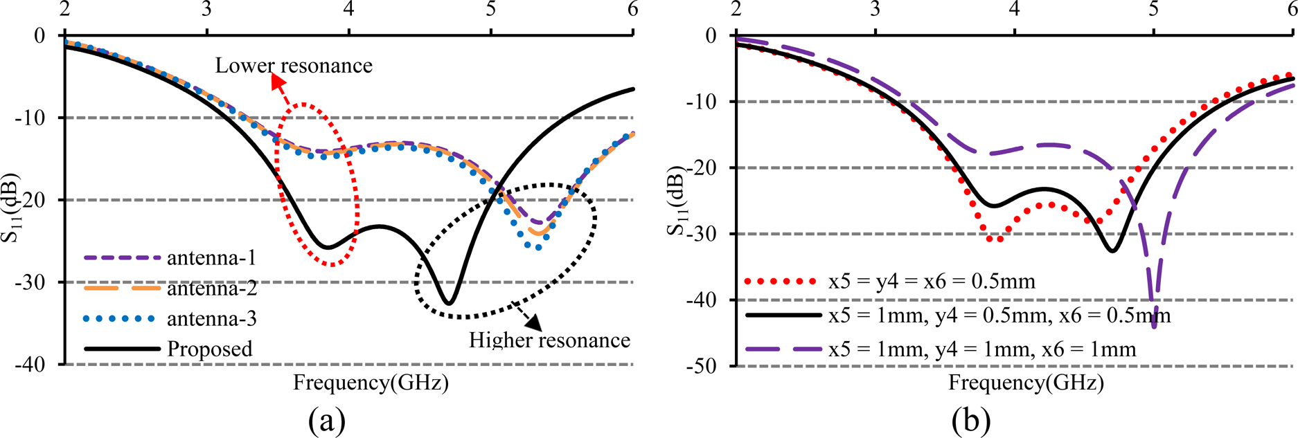
In order to fulfil the requirements of the LTE/5G operations, the studied antenna must exhibit multiple resonances. For a convenient explanation of the working principles, Fig. 2 displays the evolution process while a comparison of the simulated S 11 of different evolution steps of the antenna is presented in Fig. 3(a). First, antenna-1 is a monopole antenna comprising a steeped radiating patch of size WP × (LP + L 4) and a partial ground plane. It is clear to see from Fig. 3(a) that antenna-1 generates dual resonant modes at 3.83 and 5.34 GHz. However, the impedance matching at lower resonant mode is poor. Next, a slot of size W 1 × L 1 is inserted in the antenna-1, which forms antenna-2 as shown in Fig. 2(b). In Fig. 3(a), it is seen that insertion of slot-1 to the antenna-1 does not improve the impedance matching at lower resonant mode but it slightly lowered the S 11 value in the higher resonant mode at around 5.335 GHz that results in an increment of bandwidth by 36 MHz. The antenna-3 is composed of slot-2 and antenna-2, which excites at 3.815 and 5.305 GHz. It is seen in Fig. 3(a) that the lower resonant mode is not sensitive to the slot-2 but at higher mode, it slightly improves the performance in terms of S 11 value and operating bandwidth. To achieve the required operating band with improved S 11 value, the third slot of dimension W 3 × L 3 is inserted into antenna-3, that is, proposed antenna as shown in Fig. 2(d). In contrary to slot-1 and slot-2, slot-3 is asymmetric. The three sides of slot-3 are respectively, x 5, y 4, and x 6 mm as shown in Fig. 1(c). It is so chosen to achieve the desired antenna performance in terms of bandwidth and S 11 as shown in Fig. 3(b). From the plot, it is observed that slot-3 with unequal sides exhibits better performance than that with equal sides (x 5 = y 4 = x 6). In this design, the values of x 5, y 4, and x 6 are respectively chosen as 1, 0.5, and 0.5 mm. The inclusion of slot-3 increases the capacitive effect and enlarges the current path and the studied antenna creates a 0.25-λ resonant mode at around 3.85 GHz and a 0.33-λ resonant mode at 4.71 GHz as shown in Fig. 3(a). By merging these two resonant modes, wide operating band ranging from 3.13 to 5.529 GHz is achieved and the studied antenna is able to cover the all sub-6 GHz bands for 5G communication applications, WiMAX, WLAN, and LTE bands. The performances of all the evolution steps are summarized in Table 2.
Evolution of the proposed antenna. (a) antenna-1, (b) antenna-2, (c) antenna-3, and (d) proposed.

Simulated S 11 for (a) different antenna steps in designing process and (b) different values of x 5, y 4, and x 6.

Comparison of each step of evolution of the proposed multi-slotted antenna

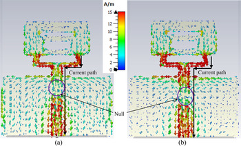
To clearly understand the working mechanism, the current distributions at two resonant frequencies of 3.85 and 4.71 GHz of the studied antenna are shown in Fig. 4. It can be clearly seen in Fig. 4(a) that, the current is mainly concentrated around the slot-3 and lower part of the feedline with a deep null. As the cutting of slot-3 enlarges the current path, this current distribution indicates that a fundamental resonance mode is generated at around 3.85 GHz. At 4.71 GHz as shown in Fig. 4(b), the current concentration around the slot-3 and upper and lower portions of the feedline are higher. It is also observed that the current null in the feedline is shifted downward. The current distribution in Fig. 4(b) and shifting of null indicates that a higher-order resonant mode is created at around 4.71 GHz. The overlapping of fundamental and higher-order resonant modes helps the studied antenna to achieve the required operating band.
Current distributions at (a) 3.85 GHz and (b) 4.71 GHz.

Parametric study
A comprehensive parametric study has been conducted to examine the effects of different dimensional parameters on impedance matching characteristics. As the slot-3 mainly generates the dual resonant modes to achieve the required operating band, its size and position have a great influence on the antenna performances and are studied. At the same time, the effect of patch and ground plane size is also studied.
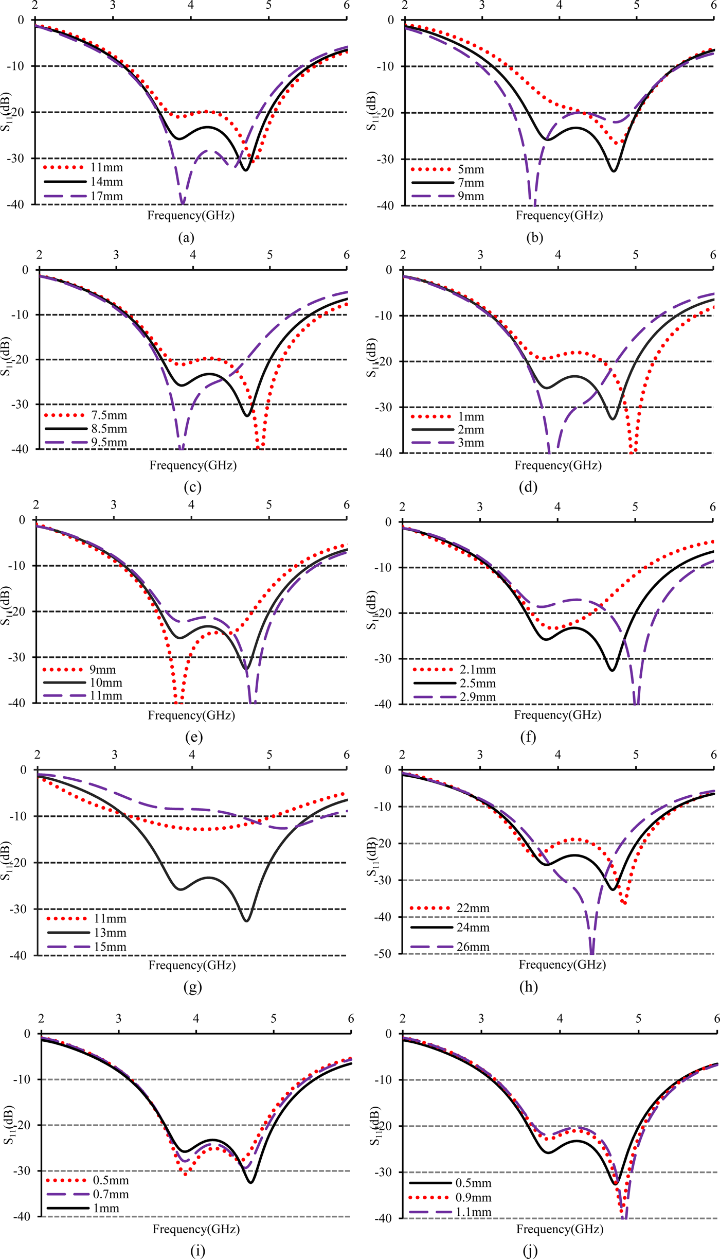
Figure 5(a) depicts the simulated S-parameters with different values of width of the patch, WP. As the patch serves as the resonating circuit for upper frequencies, the width, WP can change the input impedance results in a variation of impedance bandwidth. It can be seen that a width of 14 mm can demonstrate better S 11 value with the wider operating band. Figure 5(b) demonstrates the variation of S 11 with L P. It can be observed from the plot that decreasing of L P results in a narrow operating band while increasing of L P exhibits slightly greater operating bandwidth with poor S-parameter value especially in higher resonance frequency. In the proposed antenna, a length of 7 mm is used to get the best performance. The effect of W 3, the width of the slot-3 and L 3, length of slot-3 are respectively illustrated in Figs 5(c) and 5(d). It can be observed that both the resonances are strongly dependent on W 3 and L 3. If the value of W 3 and L 3 decreases from the optimized values, the lower resonance exhibits poor performance and higher resonance exhibits good performance in-terms of S 11 value. On the other hand, increments of W 3 and L 3 from the optimized values, exhibits good performance in lower resonance and worst performances in higher resonance. The values of W 3 and L 3 are respectively taken as 8 and 2 mm to demonstrate the best performances in terms of operating bandwidth and S 11 value. Figure 5(e) demonstrates the simulated S 11 with different values of W 4 (9, 10, and 11 mm). It can be seen that the two resonance frequencies are dependent on the value of W 4. Decreasing and increasing of W 4 from its optimized value of 10 mm demonstrates poor performances in terms of bandwidth and S 11 value. Figure 5(f) displayed the simulated S 11 for different values of L 4. It can be revealed that the higher resonance frequency is strongly dependent on the value of L 4. As the value of L 4 increases, the higher resonance frequency moves towards the upper operating band and a value of 2.5 mm exhibits the best performance in terms of S 11. The ground plane size is very sensitive in the designing of the wideband antenna. The strong dependence of operating band on ground plane size has been reported in the open literature [Reference Azim, Islam and Misran21, Reference Azim, Islam and Misran22]. Figure 5(g) displays the S 11 response for different values of LG. It can be seen in the plot that the operating bandwidth depend strongly on LG. Decreasing and increasing the value of LG from a certain value reduces the impedance matching results in a decrement of operating bandwidth. It can be commented from Fig. 5(g) that LG = 13 mm can exhibit good operating bandwidth with best S 11 value. Figure 5 (h) shows the simulated S 11 for different values of W G, the width of the ground plane. It can be revealed from the plot that, an increment of W G from its optimized value of 24 mm slightly decreases the operating band despite improved S 11 value. Moreover, a value of W G larger than the optimized one results in an increment of overall antenna size. Figures 5 (i) and 5(j), respectively, depicted the simulated S 11 for different values of x 5 and x 6, the width of two opposite edges of slot-3. In the plots, it is clear to see that a value of 1 mm for x 5 and a value of 0.5 mm for x 6 can demonstrate the better antenna performance in terms of bandwidth and overall S 11 value.
Variation of S 11 with (a) WP, (b) L P, (c) W 3, (d) L 3, (e)W 4, (f) L 4, (g) LG, (h) WG, (i) x 5, and (j) x 6.

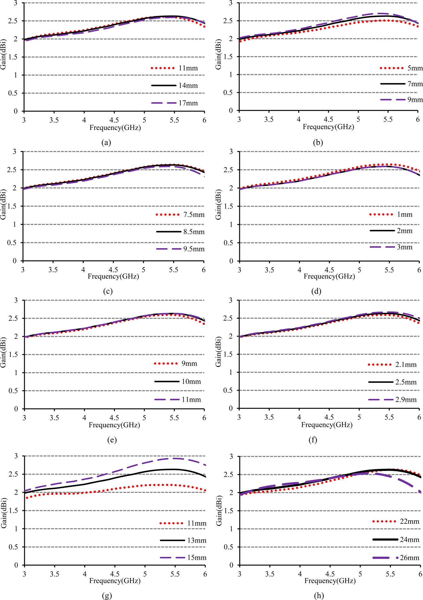
The simulated peak gain for different values of W P, L P, W 3, L 3, W 4, L 4, L G, and W G is presented in Fig. 6. From Figs. 6(a)–(f) it is seen that there are very little effects of W P, L P, W 3, L 3, W 4, and L 4 on antenna gain. As during the simulation, only one parameter is varied at a time, the variations of these parameters almost remain unaltered the antenna's overall effective radiating area. Therefore, a small change in one parameter did not affect much on antenna gain and the gain remains the same. Figure 6(g) shows the simulated peak gain for different values of ground plane length, LG. It can be revealed from the plot that, the peak gain increases with LG especially at the upper edge frequencies of the band. A larger ground plane (LG = 15 mm) may provide higher gain but the impedance matching with a larger ground plane is very poor as shown in Fig. 5(g). In this study, a length of 13 mm is taken as the optimized one to exhibits good gain with required operating bandwidth. The effect of ground plane width, WG on antenna gain is displayed in Fig. 6(h). It is clear to see that at lower frequencies WG has a little effect on antenna gain. However, at the upper edge frequency, the gain is decreased with increasing WG. Here WG = 24 mm is taken as the final value to demonstrates a good gain within the operating band.
Simulated gain for different values of (a) WP, (b) LP, (c) W 3, (d) L 3, (e)W 4, (f) L 4, (g) LG , and (h) WG.

Results and discussion
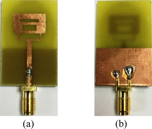
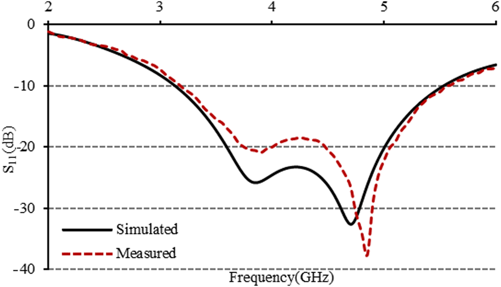
The overall performance of the designed antenna is analyzed and optimized by finite integration in technique-based CST microwave studio. The dimensional parameters of the studied antenna such as the size of the patch, slots, ground plane, feed-line are optimized to achieve the required sub-6 GHz 5G band. To experimentally verify the performance of the studied antenna, a pair of the antenna are fabricated, as displayed in Fig. 7 and its input impedance characteristics is measured with the help of N5227A network analyzer. The simulated and measured S-parameter responses of the designed antenna are displayed in Fig. 8. It can be evident from the plot that for S 11 ≤−10 dB, the proposed antenna is able to exhibit a wide operating bandwidth ranging from 3.15 to 5.55 GHz with the relative bandwidth of 55.2%. This wide impedance bandwidth can cover the existing WiMAX, WLAN, LTE 22/42/43/46 bands as well as all sub-6 GHz 5G bands. Slight discrepancy between two results is mainly due to the fabrication errors, imperfect soldering, and the effect of RF feeding cable.
Prototype of the proposed antenna (a) front view and (b) back view.

Simulated and measured S 11 of the proposed antenna.

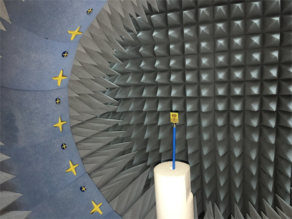
The radiation characteristics of the studied antenna are measured in MVG's StarLab near field antenna measurement system. The measurement set-up in the StarLab spherical near field chamber is shown in Fig. 9. The StarLab is capable to measure the frequencies from 650 MHz to 18 GHz. The baseline configuration is obtained by connecting StarLab to a vector network analyzer for passive antenna measurements. The dimension of the anechoic chamber is 4 m × 4 m × 8 m. The StarLab has the measurement capabilities of gain, efficiency, directivity, beamwidth, cross-polar discrimination, sidelobe level, 3D radiation pattern, and polarization pattern [23].
Radiation Characteristics measurement setup in MVG's StarLab.

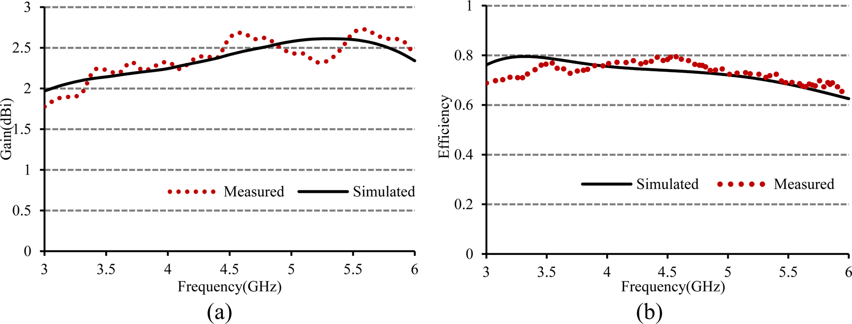
The measured and simulated peak gain of the studied antenna is presented in Fig. 10(a) while the simulated and measured efficiency is shown in Fig. 10(b). From the plot, it can be revealed that in the operating band, the designed antenna achieves an average measured gain of 2.35 dBi with a maximum of 2.69 dBi. The average measured efficiency in the operating band (3.15–5.55 GHz) is about 74.7% and the maximum efficiency is 79.6%. The achieved gain and efficiency of the designed antenna can fulfil the requisite characteristics of practical 5G applications.
(a) Peak gain and (b) efficiency of the proposed antenna.

The radiation patterns of the proposed antenna in the E-plane and the H-plane are measured at two resonance frequencies of 3.85 and 4.80 GHz. Figure 11 demonstrates the measured and simulated two-dimensional radiation patterns at 3.85 and 4.80 GHz. From the plot, it can be observed that the designed antenna exhibits almost omnidirectional radiation patterns with nulls in the bore-site directions. Moreover, the cross-polarization component is remarkably smaller than the co-polarized component. Despite some nulls, the designed antenna exhibits stable radiation patterns over the operating band which is a primary requisite for 5G wireless communication applications.
Radiation patterns at different frequencies (a) E-plane and (b) H-plane.

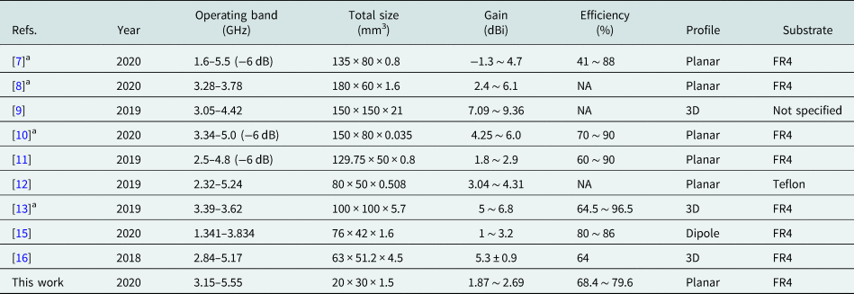
To highlight the advantages, the size and performance of the studied antenna are compared with recently reported antennae and is listed in Table 3. Obviously, the designed antenna is more compact than those reported in [Reference An and He7–Reference Jin, Deng, Yang, Xu and Liao13, Reference Gopal and Thangakalai15, Reference An, Li, Fu, Ma, Chen and Feng16] while maintaining wider operating bandwidth sufficient to cover all the sub-6 GHz 5G bands. Though some of the reported designs achieved higher gain and efficiency, their large size, complex structure, and 3D profile limit their uses in portable communications devices. Moreover, the antennae reported in [Reference Arya, Kim and Kim8, Reference Sun, Li and Xia9, Reference Jin, Deng, Yang, Xu and Liao13, Reference Gopal and Thangakalai15] do not cover all the sub-6 GHz bands. As the studied antenna possesses planar profile and requires no vertical space/large system ground plane or lumped elements, the fabrication of the presented antenna is simpler than those in [Reference Sun, Li and Xia9, Reference Sekeljic, Yao and Hsu11, Reference Jin, Deng, Yang, Xu and Liao13, Reference Gopal and Thangakalai15, and Reference An, Li, Fu, Ma, Chen and Feng16]. Therefore, the advantageous features of the proposed antenna such as small size, wide bandwidth, and ease of fabrication make it suitable for sub-6 GHz, 5G, and 4G LTE communication applications.
Comparison between the proposed and referenced antennae

a Only sub-6 GHz band is considered for comparison.
Conclusion
A low-profile multi-slotted antenna for LTE and sub-6 GHz 5G applications is designed, fabricated, and measured. The footprint of the proposed antenna is made up of a steeped rectangular radiating element with three slots and a partial ground plane and is printed on both sides of an FR4 microwave substrate. It is evident from the results that the multi-slotted patch coupled well with the ground plane and the presented antenna is able to achieve a wide operating band of 3.15–5.55 GHz (55.2%) to cover all the sub-6 GHz 5G bands, WiFi, WLAN, and LTE bands of 22/42/43/46. Moreover, it achieved good gain and efficiency and exhibits stable omnidirectional radiation patterns which make it a suitable candidate to be used in the newly introduced 5G applications in addition to the existing WiMAX, WLAN, and 4G applications.
Acknowledgement
The authors would like to thank the University Grants Commission of Bangladesh to sponsor this work under UGC Post-Doctoral Fellowship Programme 2019.
 Rezaul Azim was born in Chittagong, Bangladesh. He received B.Sc. and M. Sc. degrees in Physics from the University of Chittagong, Chittagong, Bangladesh and Ph.D. degree in Electrical, Electronic and Systems Engineering from the Universiti Kebangsaan Malaysia. In 2005, he joined the University of Chittagong where currently he is a Professor. He has been very promising as a researcher with the achievement of several medal and awards for his research and innovation. He has filed one patent application. He has authored and co-authored 47 referred journal articles, 35 conference articles, and two book chapters. His articles have been cited more than 1198 times with an h-index of 18 (Source: SCOPUS). Dr. Azim is a regular member of IEEE, IAENG, SAISE and Bangladesh Physical Society. His research interest includes the enabling technology for Antennas & Propagation. He is a reviewer of as many as 49 peer reviewed journals.
 AKM Moinul H. Meaze is a Professor of Physics at University of Chittagong (Bangladesh). He received his Ph.D. in Physics from Kyungpook National University (Korea) in 2006 and his M.Sc. (Thesis) in Physics from the University of Chittagong in 1994. He worked for several years at INFN (Italy) and CERN (Switzerland). His research interests span a broad range of areas. He has published two books and numerous journal articles.
 Adnan M. Affandi is a Professor and senior faculty member at the Department of Electrical and Computer Engineering, King Abdulaziz University, Jeddah, Saudi Arabia. He received M.Sc. (Microwave Communications) and Ph.D. (Electronic & Communications) from Kent University, Canterbury, England. His area of interest includes Microwave and millimeter circuit and devices and fiber optics communication, wireless communications, microstrip and ultra-wideband antennas.
 Md Mottahir Alam is currently a faculty member at the Department of Electrical and Computer Engineering, King Abdulaziz University, Jeddah, Saudi Arabia. Before joining academics, he worked as a Software Engineer (Quality) for around 6 years for leading software multinationals, where he worked on projects for companies like Pearson and Reader's Digest. He is also an ISTQB Certified Software Tester. His current research interest includes wireless communications, microstrip and ultra-wideband antennas, machine learning, software reusability, nanomaterial synthesis and characterization.
 Rumi Aktar was born in Chittagong, Bangladesh in 1994. She received B.Sc. and M.S. degrees in Physics from the University of Chittagong, Bangladesh in 2017 and 2018, respectively. Her research interests include antenna design for wireless communication and electromagnetics.
 Md S. Mia was born in Narsingdi, Bangladesh in 1997. He is currently an undergraduate student in the Department of Physics at University of Chittagong, Bangladesh. His research interests include microstrip antenna design, electromagnetics, microwave and RF devices.
 Touhidul Alam is currently an Assistant Professor with the Department of Computer Science and Engineering, International Islamic University at Chittagong (IIUC). He has authored and co-authored about 37 research journal articles, nearly 20 conference articles, and six book chapters on various topics related to antennas, microwaves, and electromagnetic radiation analysis. His research interests include antennas, RF, electromagnetic field and propagation, electromagnetic radiation, metamaterial applications and electromagnetic compatibility, and microwave imaging. Dr. Alam was a recipient of several international awards, including a Gold medal at the International Conference and Exhibitions by Institutions of higher learning (PECIPTA 2019), IEEE Best Paper Award 2018 (IEEE Microwave Theory and Techniques Society): IEEE AP/MTT/EMC Joint Chapter, Malaysia, Vice-Chancellor Gold Medal, 4th Convocation, International Islamic University Chittagong.
 Md. Samsuzzaman was born in Jhenaidah, Bangladesh, in 1982. He received the B.Sc. and M.Sc. degrees in Computer Science and Engineering from Islamic University Kushtia, Bangladesh in 2005 and 2007 respectively, and the Ph.D. degree from Universiti Kebangsaan Malaysia, Malaysia in 2015. He was a Postdoctoral research fellow from 2018 to 2020 at Universiti Kebangsaan Malaysia. From 2008 to 2011, he was a Lecturer with the Patuakhali Science and Technology University (PSTU), Bangladesh where he is currently an Associate Professor. He has authored and co-authored over 100 research journal articles, nearly 20 conference articles, and a few book chapters on various topics related to antennas, microwaves, and electromagnetic radiation analysis with one international patent filed. His Google scholar citation is 1036 and h-index is 17. His research interests include antenna design for communication system & small satellite, and microwave imaging.
 Mohammad T. Islam is a Professor with the Department of Electrical, Electronic and Systems Engineering, Universiti Kebangsaan Malaysia (UKM) and a visiting Professor with the Kyushu Institute of Technology, Japan. He is the author and co-author of about 500 journal articles, nearly 175 conference articles, and a few book chapters on various topics related to antennas, metamaterials, and microwave imaging with 20 inventory patents filed. Thus far, his publications have been cited 5641 times and his h-index is 38 (Source: Scopus). He was a recipient of more than 40 research grants from the Malaysian Ministry of Science, Technology and Innovation, Ministry of Education, UKM research grant, International research grants from Japan and Saudi Arabia. His research interests include communication antenna design, metamaterial, satellite antennas, and microwave imaging. Dr. Islam has been serving as an executive committee member for IEEE AP/MTT/EMC Malaysia chapter, since 2018, the Chartered Professional Engineer (CEng), a member of IET, a senior member of IEEE, and a senior member of IEICE, Japan.