Introduction
Urbanization and technological advancements have led to deployment of advanced wireless communication systems and a greater demand for defence and commercial products with enhanced features. Enhanced features mean need for multifunctionality operations at different frequencies in a single wireless device. This rising demand has motivated designers to include multiband antennas so as to meet the multifunctional requirements with controlled multibeam radiation.
Over the years, as the number of functionalities in wireless devices such as cellular mobile handsets, laptops, tablets, etc., have increased, newer frequency bands have been introduced. Hence due to the lack of space in these devices, there is a constant attempt to integrate minimum number of antennas with multiband operability. Several antenna designs ranging from printed F-antennas to fractals for wireless devices operating at GSM, UMTS, LTE, WWAN, WLAN, WiMAX, ZigBee, RFID, and portable wireless DTV are discussed in [Reference Ma, Yin, Guo and Huang1–Reference Kulkarni and Sharma7].
All the above discussions detail antennas with single beam radiation as against a multibeam multiband antenna. Multibeam antennas have the advantage of being able to be switched to limit the effect of fading due to multipath propagation. They also aid increased signal-to-noise ratio by minimizing interferences and increasing the coverage and communication capacity [Reference Toso8, Reference Hong, Jiang, Yu, Zhou, Chen, Yu and Cheng9].
Although microstrip and planar antennas are popular antenna configurations in handheld and portable wireless devices, stacked antennas are also suggested [Reference Seo and Sung10–Reference Pros and Ballarda13].
In this communication, an antenna design based on concepts of electromagnetically coupled parasitic radiators and triplate configuration is presented.
The proposed antenna comprises of a primary radiator embedded in triplate configuration with a frequency selective structure in triplate (FSST) in its nearfield and exhibits multiband multibeam operation. Based on the proposed design concept, a quad-band antenna resonating at the IEEE 802.11 WLAN frequencies and the 5 GHz band of Unlicensed National Information Infrastructure (U-NII) [14, 15] is presented.
Design methodology of an FSST-based multiband multibeam triplate antenna that exhibits frequency agility is detailed in Section “Design methodology.” Proposed FSST configuration is discussed in Section “Design considerations” with its underlying design concept in Section “Frequency selective structure in triplate.” The mathematical modeling and analysis of the concept is included in Section “Mathematical analysis” followed by experimental validations and comparisons with simulation results in Section “Results.” A comparison of the proposed antenna design with triplate antennas is also presented in Section “Results.”
Design methodology
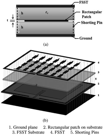
The antenna structure shown in Fig. 1(a) comprises of a radiating parent antenna (PA) sandwiched between the FSST which is configured to aid multiband and multibeam operations and the ground plane. The FSST design exploits the fact that, the microstrip patch antenna radiates at a dominant mode as well as several higher-order modes (HoMs) [Reference Bancroft16, Reference Kotrashetti and Lande17]. The basic idea here is to make the antenna radiate not only at the dominant mode of the embedded PA (a microstrip patch antenna in this communication), but also at desired higher-order mode frequencies (HMFs) by exciting specifically designed secondary radiators placed in its nearfield. The FSST comprising frequency dependent patches in the nearfield is designed such that it enhances radiation characteristics of the PA at desired frequencies.
Antenna construction: (a) side view and (b) expanded view.

The proposed concept is applied to design a quad-band antenna for low power indoor and/or outdoor equipment in wireless telecommunication systems including Internet of Things (IoT) systems which operate on fragments of the unlicensed bands: 0.915 GHz (0.902–0.928 GHz), lower WLAN 2.4 GHz (2.400–2.4835 GHz), U-NII-Mid: 5.3 GHz (5.25–5.35 GHz), U-NII-3/upper WLAN: 5.8 GHz (5.725–5.875 GHz) referred to as dominant mode frequency (DMF), HMF1, HMF2, and HMF3, respectively.
To begin with, a patch antenna designed at the lowest desired frequency of 0.915 GHz, for a given substrate and impedance matched to 50 Ω is extensively studied in [Reference Kotrashetti and Lande17] within an observation window of 0.9 GHz – 6 GHz for current density distributions, gain and radiation pattern at dominant and all HMFs that are impedance matched. The study reveals that there exists a periodic current distribution on the patch and radiation pattern is directional at the DMF, while the HMFs present growing number of beams as the mode order progresses. Also in most cases, the gain is seen to increase with mode number.
Based on this study, the radiating patch forming the PA is covered by a single-sided copper-clad substrate of dielectric constant same as that of the one below the patch. Furthermore, the copper cladding on the top (FSST) and bottom (ground) are shorted on all sides except on the side containing the feed. The direct fed radiating parent patch is symmetrically placed between the two parallel planes of FSST and the ground plane, with a separation distance equal to substrate thickness. The direct-fed radiating parent patch is placed symmetrically between two parallel ground planes with a separation distance equal to substrate thickness. Figure 1(b) illustrates the expanded view of the antenna construction. The feeding technique of the patch is discussed in Section “Design considerations.” Hence, the prerequisite study of current distribution on the patch forms the basis of FSST design.
Design considerations
A simple 50 Ω matched inset fed rectangular microstrip patch antenna (RMPA) for DMF of 0.915 GHz is designed using empirical formulae [Reference Garg, Bhartia, Bahl and Ittipiboon18] and this forms the PA. Introduction of FSST on the substrate above the PA offers larger capacitance, thus shifting the DMF on the lower side. Hence the patch dimensions are tuned to 101 mm × 127 mm (L p × W p) for εr = 2.33 Rogers substrate of h = 62 mil thickness. This frequency shift δf or depends on the dielectric constant of the substrate above the active patch i.e. FSST substrate, the net variation in the effective dielectric constant, εreff and also marginally on the area of copper over the region of PA as part of the FSST. The percentage of frequency shift due to placement of FSST on the PA is given by equation (1):

where δεreff is the change in effective dielectric constant due to substrate loading on the patch. This change in its value is no more than $5 \percnt$ of the case with no loading, i.e. δεreff ≤ 0.1
In the PA, surface waves increase with increasing substrate dielectric constant (εr) and height (h) leading to HoMs. This is a desirable condition in this case. However, radiation efficiency suffers with an increasing substrate dielectric constant although it increases with substrate height. Hence εr of 2.33 is chosen along with h of 62 mil so as to have optimum surface waves such that HoMs are excited without compromising on radiation efficiency. Length of FSST substrate (layer 3) and FSST (layer 4) is short by 10 mm with reference to RMPA contained on layer 2. This is to accommodate the 50 Ω microstrip feed line of width 4.68 mm, which gradually transpires into a 50 Ω stripline of width 2.32 mm. This aids smooth transition from microstrip to stripline. For the desired characteristic impedance of the stripline transmission line, the effective width is computed by equation (2) [Reference Hoffmann19]:

where b is the total height of the transmission line strip in triplate structure and W t−eff is the effective width of the transmission line strip in triplate structure. For a specified εr and Z o−tri, W t−tri/b can be determined by,

where,

The FSST is part of a triplate structure, shorted to the lower ground plane (layer 1) and since it is parasitically excited an increase in FSST substrate thickness (layer 3) results in reduced bandwidth.
Frequency selective structure in triplate
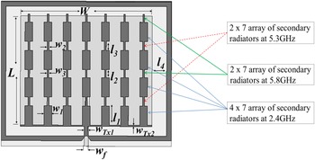
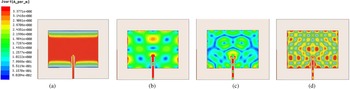
The inherent behavior of the patch to radiate at several HMFs, is used to excite an array of secondary radiators forming the FSST. One such FSST design shown in Fig. 2 is based on a careful study of current distributions on the RMPA at DMF, HMF1, HMF2, and HMF3 shown in Fig. 3 generated using High Frequency Structure Simulator [20].
FSST configuration.

Current distribution on primary radiator at DMF and desired higher order mode frequencies HMF1, HMF2, and HMF3 used for FSST design. (a) Unlicensed 0.915 GHz (TM 10). (b) Lower WLAN 2.4 GHz (TM 22). (c) U-NII 5.3 GHz (TM 35). (d) Upper WLAN/U-NII-3 5.8 GHz (TM 46).

Fig. 3 reveals that the mode at DMF, HMF1, HMF2, and HMF3 are TM 10, TM 22, TM 35, and TM 46 respectively, where TM mn mode is the transverse magnetic mode with m and n being the number of half cycle electric field variations along the length and width of RMPA respectively.
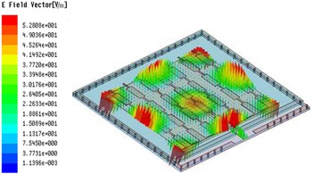
The FSST design shown in Fig. 2 is an array arrangement of secondary radiating elements comprising a 4 × 7 element array at 2.4 GHz, a 2 × 7 element array at 5.3 GHz and a 2 × 7 element array at 5.8 GHz. Each array element has length λg/4 and width λg/10 at desired HMF and are computed to l 1 = 20.123 mm, w 1 = 8.049 mm, l 2 = 9.2705 mm, w 2 = 3.708 mm, l 3 = 8.4714 mm, and w 3 = 3.3885 mm at HMF1, HMF2, and HMF3 respectively. Placement of these elements forming the secondary radiators is such that they intercept current maximas on the PA at a specific HMF. Yet, an uniformity in their placement is maintained so as to have an array configuration. The elements are arranged in seven stack arrangements, each containing quarterwavelength elements at desired HMFs alternately stacked. Each stack is maintained at a separation distance of λg/4 the HMF1. A 100 Ω transmission line (w Tx2) aligned on the lower end of RMPA on layer 2 of Fig. 1(b) holds-on to the seven stacks. The transmission line feed to the embedded RMPA carries maximum current at all frequencies. Hence the FSST design on layer 4 comprises a 50 Ω transmission line (w Tx1) electromagnetically intercepting the microstrip to stripline transition feed line of RMPA on layer 2. Given the fact that FSST is placed in close proximity to PA, the electric field parasitically excites the FSST array elements through an intermediate dielectric substrate, thus exciting it as illustrated in Fig. 4 for HMF2. Increasing the width of FSST element raises the capacitance between the PA and passive FSST resulting in reduced resonant frequency as shown in Fig. 5. Thus, frequency tuning can be done by optimizing the width of secondary radiators from λg/20 to λg/10 at specific frequencies without influencing the tuning of other desired bands. Also, gain at a specific HMF can be enhanced by increasing the number of parasitic elements excited by the PA in FSST. Hence the gain at a particular frequency can be altered by changing the number of elements in array configuration of the FSST at the desired frequency. An increase in FSST substrate height results in lesser field excitation of the FSST and hence reduced bandwidth as shown in Fig. 6. To ensure that RMPA continues to radiate as per its inherent characteristics despite being embedded within the triplate configuration, an optimized substrate extension of λg/8 (at DMF) from PA is maintained.
FSST excited by primary radiator at TM 22, 2.4 GHz.

Effect of variation in width of FSST element.

Effect of FSST substrate height.

Hence FSST (the secondary radiator) is said to enhance the radiation characteristics of RMPA (the parent antenna) at HMFs.
In case of an FSST with slots [Reference Kotrashetti, Lande and Sundararajan21], the average radiation efficiency is seen to reduce over the four bands. If FSST is kept floating, the frequencies are detuned, in which case, the antenna is to be treated as a stacked antenna and appropriate analysis to be applied for optimization.
Mathematical analysis
As discussed, the antenna is fed through a microstrip transmission line which transpires into a triplate configuration. Applying transmission line theory the feed is modeled by series R is, L is, and shunt G is, C is which are normalized to length parameters, representing the resistance of conducting transmission line in Ω/m, inductive behavior of a conductor at high frequencies in H/m, shunt conductance representing the leakage current path in the substrate below the microstrip transmission line and the lower ground plane in S/m, and capacitance between the feed line and ground plane separated by a dielectric material in F/m, respectively as shown in Fig. 7. Furthermore, the PA being a patch is modeled by a one-port Foster series network with series of resonant circuits representing the higher order mode resonances of the patch along with the dominant resonance. This forms the basis on which the electrical equivalent model for the antenna is built.
Equivalent model of the antenna.

The dominant mode of TM 10 is represented by a parallel resonant circuit given by L 10, C 10 and R 10. R mn−p denotes substrate, conductor, and radiation losses at different mode frequencies and is given by,

At very high frequencies R 10 is negligible. Further,

where G rad and G die are the conductance due to radiation and dielectric substrate losses, while G cu is the conductance loss with reference to the applied input voltage. Furthermore,

Here, Q s is the quality factor at the resonant mode:

Here, L, W, h are the patch length, patch width, and substrate thickness respectively. R s is the conductor series resistance in a lossy medium expressed as,

The substrate dielectric conductance, G cu representing the leakage path in the dielectric material or the dielectric losses is,

where tanδℓ is loss tangent of the substrate material used. C mn is mode capacitance and depends on variations of the field along the length and width of the patch. The capacitance in the dominant mode represented by, C 10 is dependent on the DC capacitance C DC and the half-wavelength variations along the length of the patch cos(πL g/L) and is expressed as,


L g is the inset feed distance for an inset fed patch and for a probe fed patch, distance to feed point. The capacitance in the HoM representations, C mn is dependent on the DC capacitance and the half-wavelength variations along both the length and the width of the patch. It is expressed as,

X f is the distance to the feed-point from the edge of the width. The inductance at HoMs is computed at resonance, wherein,

As the mode order increases, the resistance becomes negligible and the combined HoMs together form a series inductance L oT which includes the half-wavelength field variations along both the length and width of the patch and is expressed as,

ωmn is the complex resonant frequency of the mnth mode with indices m and n being the indices for HoMs in consideration. It is given by [Reference Garg, Bhartia, Bahl and Ittipiboon18],

and ζmn is given by,

The mode dependent width of the feed is expressed as,

For coaxial feed dx = dy and the cross-sectional area dxdy is set equal to effective cross-sectional area of the probe. In case of transmission line feeding at L g = 0 sets dy = 0 and dx is considered to be the feedwidth. In the antenna design dx = 4.678 mm and since the patch is inset fed, dy = 0. Therefore,

Furthermore, in Fig. 7, C is which forms the capacitance below the feedline is deduced by,

Also, C d0, C d1, C d2,…, $C_{d_p-1}$ , C dp are the DC capacitances in the FSST substrate between the FSST and radiating patch. G d, G d1, G d2,…, $G_{dp-1}$
 , G dp represent leakage current path in the substrate and a typical value equal to inverse of insulation resistance of a dielectric material (105 MΩ) is considered.
As discussed the patch radiations excite an FSST designed to radiate at more than one HMFs. The FSST comprises secondary radiators only at HMFs and not DMF. Hence in the electrical equivalent, FSST composition is of parallel RLC resonant circuits at HMFs only. L mn1−1, C mn1−1, and R mn1−1, L mn2−2, C mn2−2, and R mn2−2, and subsequently L mnp−p, C mnp−p, and R mnp−p, represent the resonant circuits at HMF1, HMF2, and HMF3 and so on till the pth HMF respectively. Since the secondary radiators are of varied lengths and widths, owing to the HoM frequency they are designed for, different inductance, capacitance, and resistance are offered. Hence the quality factor provided at each HMF is also different. Based on this discussion, the resonant components of the FSST are formulated.
Capacitance representations due to FSST elements are formulated as,

Equation (20) although on the same lines as equation (13), DC capacitance between the patch and FSST element at the HMF given by C DCmn is defined with respect to area of the secondary radiators at the HMF whereas in equation (12) the DC capacitance was computed with reference to the total patch area. Hence for each HoM radiation the DC capacitance will vary:

where W mn and L mn are the width and length of the secondary radiating element patches in the FSST at desired HMF and h ms is the thickness of substrate placed between the patch and FSST. At resonance,

Resistance offered by FSST elements at higher order mode representations is,


where G cup−p, G radp−p, and G diep−p represent conductor, radiation, and dielectric substrate losses respectively of the FSST elements. They are further elaborated as follows,


The model presented can be treated as a one port network and the driving point impedance or input impedance of the antenna, under lossless conditions is expressed as,

where − jB ot is the inductive susceptance of the total series inductance. Y mnp−p, Y mnp−1,…, Y mnp−2, Y dc are the shunt leg admittances given by equation (30) while Z mn−p, Z mnp−1,…, Z mn−1, Z 0 are the series leg impedances given by equation(31):


The mathematical model is implemented for the antenna specifications discussed in Section “Design methodology” for analysis. The model with component values deduced from equation (5) to equation (27) is simulated to compute the S 11 for each of the HMFs and input impedance at the port. Satisfactory reflection coefficient values are obtained at the four HMFs and the input impedance is Z in = 55.72 + j0.24Ω which stands matched.
Results
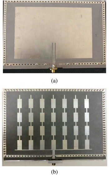
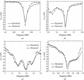
The fabricated antenna is shown in Fig. 8. Measured reflection coefficient of the antenna, are seen to be in congruence with the simulated values in Fig. 9. An average radiation efficiency of 0.94 is noted over all four bands with no FSST/only RMPA and it reduces to 0.86 with FSST. A comparison of peak gain and 2:32 VSWR bandwidth (computed at return loss of − 8 dB) at each HMF for RMPA without and with FSST is tabulated in Table 1.
Fabricated antenna for assembly: (a) Parent antenna – RMPA without FSST placed on it and (b) Antenna with FSST on the top.

Comparison of measured and simulated S 11 at DMF, HMF1, HMF2, and HMF3. (a) Unlicensed 0.915 GHz (TM 10). (b) Lower WLAN 2.4 GHz (TM 22). (c) U-NII Mid 5.3 GHz (TM 35). (d) Upper WLAN/U-NII-3 5.8 GHz (TM 46).

Gain and bandwidth improvement for antenna with FSST

.
The gain is observed to increase with the FSST at HMFs in comparison with “No FSST.” Gain at a particular HMF can be altered by the number of secondary elements in the FSST i.e. by changing the array configuration of the FSST.
This is evident in Table 1 where, at HMF1 the gain is seen to double “With FSST,” since 4 × 7 array elements are excited at this frequency. Whereas, at HMF2 and HMF3 approx 25$\percnt$ increase is noted since 2 × 7 elements are excited. The bandwidth measurements reveal that the FSST enhances bandwidth at all HMF bands while it slightly suffers at the DMF band. This bandwidth reduction at DMF is on account of confinement of the primary active element between the FSST and ground planes resulting in high Q.
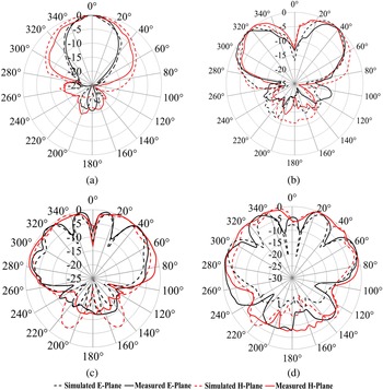
Congruence is seen in the measured and simulated E- and H-plane radiation patterns shown in Fig. 10. In this design concept, the antenna exhibits multibeam radiation by virtue of characteristics of the PA at HoMs unlike multibeam antennas where beamforming networks are employed [Reference Toso8, Reference Haneishi, Matsui, Nakayama and Saito22]. However, at a given frequency, the number of beams cannot be varied since it depends on the order of the mode.
Comparison of measured and simulated E- and H-plane radiation patterns at DMF, HMF1, HMF2, and HMF3 of proposed antenna. (a) Unlicensed 0.915 GHz (TM 10). (b) Lower WLAN 2.4 GHz (TM 22), (c) U-NII Mid 5.3 GHz (TM 35). (d) Upper WLAN/U-NII-3 5.8 GHz (TM 46).

A comparison of the proposed antenna with existing triplate antennas is tabulated in Table 2. Antennas discussed in [Reference Haneishi, Matsui, Nakayama and Saito22–Reference Hasegawa and Arai26] employ network of feed lines embedded within the triplate which excite slots or aperture fed patches for radiation. These antennas have single band single beam operation while the proposed antenna exhibits multiband operation with multiple beams and slightly compromised gain in comparison to them.
Comparison of proposed antenna with referenced triplate antennas

Conclusion
The radiation mechanism of the proposed antenna is based on the concept of nearfield excitation of parasitic elements placed methodically in close proximity to a parent exciter. The concept enables design of a multiband multibeam conformal antenna predominantly dependent on the design of a FSST.
The primary exciting antenna has several HoMs and based on the application requirement, FSST can include secondary radiators at specific HMFs, configured in any logical pattern for the same parent antenna. This goes to say that for a single parent antenna, a variety of FSST designs can exist. This enables easy upgradation to higher frequencies of operation over and above operations at pre-existing lower bands as and when newer higher frequency deployments take place. Also the structure can be made conformal with proper choice of substrate. The FSST is observed to have enhanced the radiation characteristics of the parent exciter while its design simplicity is maintained.
Multibeam radiation at multibands can augment transmission-reception if the beams are switched in directions of maximum reception and/or used for null switching. An integration of a phase shifting mechanism into the antenna shall result in controlled beamsteering thus making it an intelligent antenna, which is upcoming research of the authors.
Acknowledgment
The authors express their heartfelt gratitude to Late. Prof. D Sundararajan, for his wholehearted guidance and valuable inputs.
 Ashwini Kotrashetti graduated in Electronics & Communication Engineering from Karnatak University, India; Masters in Telecommunication Engineering from Mumbai University, India; and Doctorate from Assam Don Bosco University, India. She is an Associate Professor heading the Department of Electronics & Telecommunication Engineering, Don Bosco Institute of Technology, Mumbai, India. She is a IEEE Senior Member with research interests in metastructure antennas, SIW-based passive components, and microwave farming.
 B. K. Lande graduated in 1973; he has an M.E. degree from the Walchand College of Engineering Sangli, India. He obtained his Ph.D. degree from the Indian Institute of Technology Bombay, India. He worked in VJTI, Shah & Anchor Kutchi Engineeing College, Mumbai and School of Engineering & Technology, Swami Ram Himalayan University, Dehradun, India. His current interests are controls and communication engineering.
 Ajay Poddar is an IEEE Fellow, graduated in Electronics & Communication Engineering from the National Institute of Technology Calicut, India; Master of Technology from the Indian Institute of Technology Delhi, India; Doctorate (Dr.-Ing.) from Technical University Berlin, Germany; Post-Doctorate (Dr.-Ing. habil) from Brandenburg Technical University, Cottbus, Germany. He has received over dozen awards for scientific and technological innovations and meritorious services; over three-dozen patents, has published 250+ scientific papers in journals and conferences, and co-authored four technical books/chapters. Previously he has worked as a Senior Scientist in DRDO and visiting Professor at the University of Pune, India. Presently, he is working as a Chief Scientist at Synergy Microwave, NJ, USA; responsible for design/development of signal generation/processing electronics, opto-electronics, RF-MEMS, and metamaterial-electronics for industry, medical and space applications. He is also serving as a visiting professor in the University of Oradea, Romania, Indian Institute of Technology Jammu, India, and guest lecturer in Technical University Munich, Germany.