I. INTRODUCTION
Instrumented indentation and specially nanoindentation has provided us with a high-resolution tool for characterizing the mechanical properties in very small specimens or in very localized volumes. The well-known work by Oliver and PharrReference Oliver and Pharr1 set the conditions for a standard procedure to measure both hardness and Young’s modulus of materials by means of this technique. Based on Sneddon’sReference Sneddon2 work on purely isotropic elastic contact, Oliver and Pharr showed that the elastic unloading could be related to the indentation-reduced elastic modulus (M r) as follows:
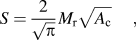
where S is the unloading stiffness at maximum load and A c is the projected contact area between the surface of the sample and the indenter. The stiffness contribution of the indenter can be corrected as follows:

where  and
 are, respectively, the indentation modulus of the sample and the indenter. In the case of elastically isotropic materials, the indentation modulus reduces to the well-known expression:
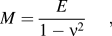
where E is the Young’s modulus and ν is the Poisson’s ratio.
The work by Oliver and Pharr has two main limitations: (i) the contact area is not obvious since sink-in and pile-up phenomena may occur in the neighborhood of the indentation depending on both the elastic and plastic properties of the sampleReference Alkorta, Martinez-Esnaola and Sevillano3, Reference Alkorta, Martinez-Esnaola and Sevillano4 and (ii) the indentation modulus may vary with the crystal orientation as a consequence of the elastic anisotropy of the crystal.
The first limitation can be circumvented if the indentation modulus is calculated from the initial elastic loading segment of the indentation. This can be done from the analysis of very shallow indentations if the transition from elastic to elastic–plastic regime can be detected (pop-in phenomenon indicative of early plasticity) and provided no surface layer or film disturbs the accurate measurement of the indentation modulus. With regard to the elastic anisotropy, the works by Vlassak et al.Reference Vlassak, Ciavarella, Barber and Wang5–Reference Vlassak and Nix7 and Swadener and PharrReference Swadener and Pharr8 led us to an analytical procedure to calculate the indentation modulus for a general axisymmetric problem by considering an elliptic contact area and assuming that the solution for the contact problem is the one that maximizes the load on the indenter for a given indentation depth. Further details of this procedure are given in Ref. Reference Vlassak, Ciavarella, Barber and Wang5.
Our work aims to analyze the ability of nanoindentation to evaluate the elastic anisotropy in a controversial case study: the cementite or iron carbide (Fe3C).
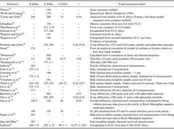
Cementite is a basic component of many steels and cast irons and is also of geological interest; however, despite its importance there is no consensus at all on the values of its elastic constants.Reference Ledbetter9 Appendix A shows a collection of the elastic properties of cementite recorded by several authors from first-principle calculationsReference Jiang, Srinivasan, Caro and Maloy10–Reference Ono and Mibe21 and experimental measurements.Reference Ledbetter9, Reference Ono and Mibe21–Reference Fiquet, Badro, Gregoryanz, Fei and Occelli46 The wide spread of the experimental results is partly due to the difficulty of obtaining a direct accurate value of the Young’s modulus but could also be due to the high anisotropy of elastic properties predicted by ab initio calculations. The occurrence of a second crystal structure of cementite when embedded in ferrite as thin lamellae or particles has also been suggested as another source of spread of the results.Reference Ledbetter9
The present work tried to evaluate the indentation modulus of cementite (Fe3C) at different orientations by combining electron backscattered diffraction (EBSD) and nanoindentation measurements. The experimental results were compared to the expected values evaluated by the analytical procedure proposed by Vlassak et al.Reference Vlassak, Ciavarella, Barber and Wang5 and the elastic constants of Fe3C reported in literature from ab initio calculations.Reference Jiang, Srinivasan, Caro and Maloy10 Moreover, the first pop-in events, which are closely connected to the onset of plasticity, were analyzed to check its dependence on the crystal orientation of the cementite.
II. EXPERIMENTAL PROCEDURE
A mottled cast iron sample (composition: Table I) was cut into three perpendicular planes, grinded, and carefully polished using a standard metallographic preparation schedule. As a final step, the sample was subjected to 30 min of polishing with a colloidal silica suspension in water to remove any oxide film or deformed layer from the surface of the sample.
Composition of the cast iron analyzed.

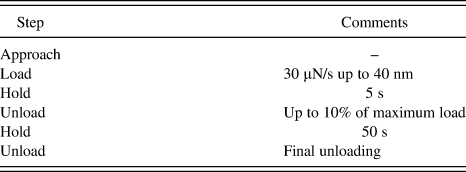
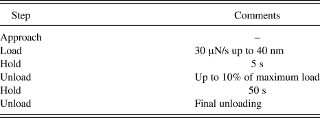
EBSD measurements were carried out in a Jeol JSM-7000F (JEOL) equipped with a HKL Channel 5 EBSD with Nordlys II detector. For each of the three sample orientations, 3–5 large cementite crystals were selected and at least 25 indentations per Fe3C orientation were performed in a Nanoindenter II (MTS–Agilent) using a Berkovich indenter. The nanoindentation procedure followed is detailed in Table II.
Procedure followed in the nanoindentation measurements.
From the classical Hertzian contact, we get:
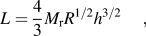
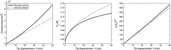
where L is the applied load, h is the tip displacement, M r is the indentation modulus, and R is the indenter radius. The indentation modulus M r was calculated from a linear regression of the curve h versus L 2/3 (h < 10 nm) once the tip roundness (R = 290 ± 10 nm) was evaluated with a fused silica calibration sample. The good linearity of the observed h versus L 2/3 curves confirms the spherical character of the tip and validates its use for the determination of the indentation modulus, M r. The mean pressure at the onset of plasticity (first pop-in event) was calculated by considering the load (L) and the tip displacement (h) at the first pop-in event, assuming a contact area calculated for purely elastic behavior using Sneddon’s analytical approach for a rigid rounded conical indenter [see Appendix B and Eqs. (B6) and (B7)]. Figure 1 shows that the rounded conical behavior deviates from the Hertzian spherical behavior [Eq. (6)] at h ∼10 nm.
Comparison between the spherical (Hertzian) elastic contact (dashed line) and rounded conical elastic contact (solid line) for R = 290 nm. From left to right, contact area, normalized mean pressure, and L 2/3 versus tip displacement. See Appendix B.

Parallely, elastically anisotropic three-dimensional finite element analysis (FEA) was conducted in a commercial code (ABAQUS 6.8) to compare them with the experimental results and analytical calculations. A rigid spherical punch was considered, without friction on the basis that for elastic contact, in which extensive sink-in occurs, friction has little effect.Reference Cao, Qian and Huber47, Reference Taljat and Pharr48 The following elastic constants were assumed (after Jiang et al.,Reference Jiang, Srinivasan, Caro and Maloy10 bold row in Table A1 in Appendix A). Forty-nine simulations were carried out at different sample orientations. The indentation modulus was calculated from the load–displacement response curves, and the stress fields were recorded to determine the maximum shear stress as a function of the crystal orientation.
III. RESULTS AND DISCUSSION
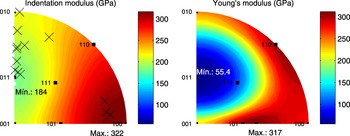
Figure 2 shows the contour plot in the stereographic projection of the crystal poles perpendicular to the sample surface, corresponding to the indentation modulus (right) calculated using the same procedure as Vlassak et al.Reference Vlassak, Ciavarella, Barber and Wang5 and Young’s modulus (left) calculated from the elastic constants obtained from ab initio calculations by Jiang et al.Reference Jiang, Srinivasan, Caro and Maloy10 (see Appendix A); superposed in black crosses, the orientation of the crystals studied experimentally. The analytical results show that the anisotropy of indentation modulus is lower than in a conventional uniaxial test as a result of the high triaxiality of a spherical elastic contact. The maximum indentation modulus corresponds to a crystal orientation with the (100) pole oriented perpendicular to the sample surface, whereas the minimum indentation corresponds to a (011) pole. Young’s modulus, in contrast, shows a maximum value in the neighborhood of (110) and (101) poles.
Stereographic projection of indentation modulus (left) calculated using the procedure proposed by Vlassak et al.Reference Vlassak, Ciavarella, Barber and Wang5 and Young’s modulus (right) corresponding to the elastic constants obtained from ab initio calculations by Jiang et al.Reference Jiang, Srinivasan, Caro and Maloy10 (see Appendix A). Crosses correspond to the stereographic projection of the crystallites analyzed experimentally.

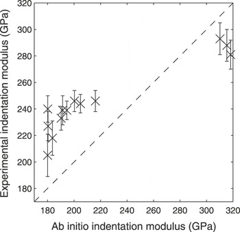
Figure 3 shows the experimental indentation modulus versus the indentation modulus calculated with the ab initio elastic constants according to Vlassak et al. for the same orientations. The experimental results show a trend similar to that predicted from ab initio calculations and a similar mean indentation modulus. However, the measurements show a lower elastic anisotropy than the results coming from ab initio calculations.
The experimental indentation modulus measured by nanoindentation versus the full range of indentation modulus calculated from the ab initio elastic constants calculated by Jiang et al.Reference Jiang, Srinivasan, Caro and Maloy10

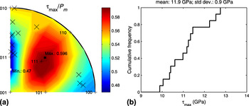
The finite element analyses carried out give values of the indentation modulus for the spherical indenter that coincide accurately (within <1%) with the values obtained using the analytical procedure proposed by Vlassak et al. However, FEA results provide us with the full stress field information in the indented material so that the maximum shear stresses (τ max) beneath the indenter for the first plasticity event can be easily calculated (see Fig. 4). For isotropic materials, the maximum shear stress is τ max = 0.47·P m. The load in which the pop-in occurs is related to the dislocation nucleation or multiplication under the indenter tip. The considerable narrow distribution of the recorded pop-in loads for each cementite crystal and the large critical shear stresses involved indicate that homogeneous nucleation of dislocation is determining the onset of plasticity. The results show a nearly constant critical shear stress for incipient plasticity (first pop-in) regardless of the crystal orientation (a mean critical shear stress of 11.9 GPa with a standard deviation of 0.9 GPa). It is known that indentation is rather insensitive to plastic anisotropy.Reference Khan, Brown and Chaudhri49
(a) Contour plot in stereographic projection of the maximum shear stress to mean pressure ratio (τ max/P m) calculated by finite element analysis (FEA). (b) Cumulative frequency of the absolute value of the critical shear stress for early plasticity obtained in nanoindentation measurements.

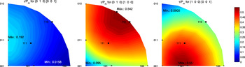
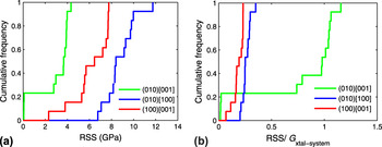
Furthermore, Fig. 5 shows the maximum shear stress on the three most prominent gliding systems of cementite (respectively, (010)[001], (010)[100], and (100)[001]) normalized by the applied mean pressure (P m). Figure 6 shows the actual resolved shear stresses (RSSs) at the onset of plasticity in GPa and normalized by the shear modulus of each slip system as calculated from the elastic constants obtained by Jiang et al.Reference Jiang, Srinivasan, Caro and Maloy10 In terms of the RSS normalized by the shear modulus of each slip system, the (010)[001] system is by far the most stressed one and it is likely the active system but for a few cases which correspond to the (100) orientation. The huge τ max/Gxsystem ratio for the (010)[001] system is probably due to an extremely low shear modulus caused by an overestimated elastic anisotropy in ab initio calculations.
Contour plots in stereographic projection of the resolved shear stress (normalized by the indentation pressure) along the three crystal systems quoted for orthorhombic Fe3C obtained from FEA by assuming elastic behavior and the ab initio elastic constants.

(a) Resolved critical shear stresses at the onset of plasticity for each of the three primary slip systems. (b) Resolved critical shear stresses normalized by the shear modulus of each slip system calculated from the elastic constants from ab initio calculations by Jiang et al.Reference Jiang, Srinivasan, Caro and Maloy10

IV. CONCLUSIONS
Nanoindentation has been shown a useful technique to evaluate the elastic anisotropy of cementite and could as well be used for assessing the elastic anisotropy of other materials difficult to test with macroscopic elastic methods. The validity of the analytical solution proposed by Vlassak et al.Reference Vlassak, Ciavarella, Barber and Wang5 has been confirmed by FEA.
The results obtained up to now show that the elastic anisotropy of Fe3C is high but not as high as available ab initio calculations predict. The values of the Young’s modulus appear to follow a similar trend in their relationship with the orientation as the calculated ab initio values.
Further systematic studies are needed (with, for instance, pure iron–carbon alloys, our cementite is an alloyed cementite) to improve our knowledge.
With respect to the cementite plastic strength, the experimental results show that the maximum shear stress under the indenter at the onset of plasticity depends only weakly on the crystal orientation (τ crit ∼11.1 GPa with a standard deviation of 0.9 GPa). The first slip system to be activated is (010)[001] for most of the orientations. However, a quantitative determination of its critical RSS requires a better knowledge of the actual values of the elastic constants of cementite.
ACKNOWLEDGMENTS
This research was funded by the Basque Government (SAIOTEK 2006, Project UET 120905) and by the Belgian State (Belgian Science Policy, Interuniversity Attraction Poles Programme Project P6/24).
APPENDIX A: REVIEW OF ELASTIC PROPERTIES OF CEMENTITE
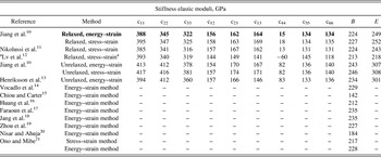
This is a summary of the elastic moduli of cementite reported by different authors using first-principle calculations and experimental measurements. Table A1 shows the elastic properties calculated from first principles by different authorsReference Jiang, Srinivasan, Caro and Maloy10–Reference Ono and Mibe21:
Compilation of elastic moduli obtained from first-principle calculations by different authors.

a Data from Lv et al.Reference Lv, Zhang, Sun, Wang, Jiang, Zhang and Fu12 do not match the elastic stability criterion (c44 < 0). The elastic constants considered in this work are given in bold.
Table A2 shows a compilation of elastic properties (bulk modulus, B; Young’s modulus, E; shear modulus, G; and Poisson’s ratio, ν) of cementite measured by different authors using different techniques. Some of the characteristics of the measuring methods are also briefly described:
Compilation of elastic moduli obtained from experimental measurements by different authors using different techniques in chronological order.
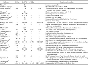
a Works reported by Ledbetter.Reference Ledbetter9
APPENDIX B: ELASTIC CONTACT OF A RIGID ROUNDED CONICAL INDENTER
A rounded conical indenter can be expressed in terms of the first two terms in a standard calibration procedure in nanoindentation as follows:

where A c is the projected contact area and h c is the depth from the contact level. If we define a as the contact radius and ϕ as the indenter angle (ϕ = 70.3 for an equivalent Berkovich indenter), then the calibration constants A and B can be easily calculated and Eq. (B1) leads to:

and

where α = (a/R) tanϕ.
Then, following Sneddon’sReference Sneddon2 procedure, the normalized rounded indenter profile can be described as follows:

According to Sneddon, the applied load (L) and tip displacement (h) can be calculated as follows:

where E r is the reduced Young’s modulus. If we solve Eq. (B5) from Eq. (B4), we get:

and

It is easy to see that Eqs. (B6) and (B7) lead asymptotically to Sneddon’s solutions for spherical and conical indenters.
Note that this solution is only valid for elastically isotropic materials. However, we can consider that it is also valid for anisotropic materials (by considering its effective indentation modulus, M r instead of the reduced Young’s modulus, E r) on the basis that the indentation modulus for a given material is very similar for both conical and spherical indenters (Vlassak et al. Reference Vlassak, Ciavarella, Barber and Wang5).