I. INTRODUCTION
The development of feasible nuclear fusion power requires the use of materials that can withstand exposure to high doses of high energy (14 MeV) neutron radiation, particularly in the ‘first wall’ plasma facing (structural) components. Selection of materials for such applications is problematic.Reference Schiller1 Not only must the material withstand radiation for long periods of time without deleterious changes in mechanical properties but the elements comprising the material must be ‘low activation,’ transmuting only to isotopes that are either short lived or stable. Such constraints severely limit the choice of possible materials. Candidate materials include SiC/SiC composites, W, V–Cr–Ti alloys and Cr-steels; the steels have been designed to exclude certain normally desirable but high activation elements, such as manganese, niobium, nickel, and molybdenum.Reference Bloom, Zinkle and Wiffen2 Neutron radiation damage causes hardening and embrittlement of alloys through displacement of atoms from their lattice sites and the generation of lattice vacancy/self-interstitial point defects (Frenkel pairs). The majority of these defects annihilate with one another. However, many migrate within the lattice to form dislocation loops, voids, and clusters.Reference Yao, Hernandez-Mayoral, Jenkins and Kirk3 The increased vacancy population can enhance diffusional processes, leading to creep and to segregation of alloying elements to grain boundaries.Reference Mansur4 Hardening of alloys due to irradiation is attributed to several mechanisms.Reference Suganuma and Kayano5, Reference Heintze, Bergner and Hernandez-Mayoral6 The dislocation loops are regarded as barriers to dislocation flow through a classical Taylor hardening type mechanism, the increased flow stress being proportional to the size and spacing of dislocation loops. Alloy segregation is considered to make an additional contribution. There is evidence from transmission electron microscopy (TEM) observations for both these mechanisms.Reference Suganuma and Kayano5, Reference Heintze, Bergner and Hernandez-Mayoral6 However, this does not explain all of the additional hardening and pinning of dislocation sources by point defects, via a Cottrell locking mechanism, is also considered a potential contributor, although such defects cannot be observed in the TEM.Reference Heintze, Bergner and Hernandez-Mayoral6 Laboratory simulation of these damage mechanisms can be achieved without the need to create radioactive materials through self-implantation of high energy heavy ions. Such facilities are designed for controlled implantation of ions with energies typically around 3 MeV. However, the penetration of ions is limited by the beam energy to the order of a micrometer below the material surface forming a thin damage layer, making the investigation of bulk mechanical properties unachievable by conventional mechanical testing but highly suitable for investigation by nanoindentation methods.
The surface mechanical properties of ion implanted layers in nonmetals have been investigated previously by nanoindentation for implantation of Ti,Reference Boudoukha, Halitim, Paletto and Fantozzi7 Nb,Reference Bauer, Kapsa, Loubet, Ramos, Canut, Gea and Thevenard8 and CReference Murphy, Laugier, Beake, Sutton and Newcomb9 into sapphire and polycrystalline alumina and implantation of N and B into SiC,Reference Roberts and Page10 the amorphization of the surface changing tribological and wear properties. For irradiated metals, the mechanical response to nanoindentation may be more complex. Once plasticity is initiated, strain softening is possibleReference Farrell and Byun11 as point defects and dislocation loops are swept out by dislocations in an analogous manner to mechanical annealing.Reference Shan, Mishra, Syed Asif, Warren and Minor12 The plastic zone may extend through the irradiated layer and into material beneath where radiation damage has not penetrated, also appearing as an apparent softening, in an analogy to the indentation response of a hard coating on a softer substrate.Reference Bull13 The usual issues of the indentation size effectReference Bushby, Zhu and Dunstan14 and the pile-up or sink-inReference Johnson15–Reference Lim and Chaudhri17 of material at the contact may also confound the measurement process as plasticity progresses. The use of spherical indenters has some potential advantages in exploring the behavior of the irradiated layer in that the elastic-plastic transition can be clearly identified both with and without the occurrence of pop-in (elastic overload),Reference Zhu, Bushby and Dunstan18 the evolution of plasticity can be followed as a function of indentation strain, in analogy to a tensile stress–strain curve. Furthermore, the elastic modulus can be determined as a function of penetration depth and, before the initiation of plasticity, without the uncertainties associated with an elastic-plastic indentation.
In this article, we use spherical nanoindentation to investigate the properties of a model ferritic Fe–Cr alloy under conditions of exposure to a high radiation dose of Fe+ ions compared to the same material unirradiated. Spherical indenters with a range of radii were used to initiate plasticity within the damaged layer near the surface. The critical measurement issues associated with nanoindentation of the damage layer are also explored.
II. MATERIALS AND METHODS
Polycrystalline Fe–12%Cr alloy was supplied for this work by Metals, Crystals, and Oxides Ltd., Cambridge, United Kingdom. The material was purchased as 99.999% pure; however evidence of carbon impurities has been seen during sample preparation and in the Atom Probe. The material was annealed at 830 °C +/−10 °C for 72 h to develop a large equiaxed grain structure. Grain diameters were determined by electron backscattered diffraction to be in the range from 20 to 450 μm, with a mean grain size of 147 μm. The sample was subsequently polished with colloidal silica to obtain a clean, mirror finish surface with minimal cold work/polishing damage. Implantation of Fe+ into the sample surface took place at National Ion-Beam Center at the University of Surrey, United Kingdom. A two-step irradiation was used in attempt to achieve a more uniform distribution of damage throughout the near surface layer, equivalent to 6 displacements per atom (dpa). To achieve this implantation with 2MeV ions to a dose of 3 × 10¹⁵ions/cm2 was followed by 0.5 MeV ions to a dose of 1 × 10¹⁵ions/cm2. The damage distribution was modeled using a Monte Carlo simulation code ‘TRIM’ (http://www.srim.org/). These calculations used an average of 1000 ions in pure iron, using the recommended displacement energy of 40 eV (from ASTM E521, Neutron Radiation Damage Simulation by Charged-Particle Irradiation). The temperature was held constant at 320 °C during implantation and was measured by a thermocouple clamped within a dummy sample. Dose rate varied from 3.5 to 7.5 × 10⁻⁴ dpa/s (average ∼5 × 10⁻⁴ dpa/s). Part of the sample area was masked to provide unirradiated areas on the same sample. All the experiments reported here were conducted within a single grain of ∼400-μm diameter containing both irradiated and unirradiated areas.
Nanoindentation experiments were conducted using a UMIS 2000 nanoindentation instrument (CSIRO, Lindfield, NSW, Australia) equipped with a series of spherical indenter tips with nominal radii, R, of 5, 10, and 20 μm. Indenter tip shape and instrument frame compliance were calibrated using the multiple reference material method as detailed in Ref. Reference Zhu, Bushby and Dunstan18. Indentation arrays were created, with 20 μm spacing between adjacent indents, that spanned both irradiated and unirradiated material within a single crystal grain to directly compare elastic and plastic mechanical responses without the complication of different grain orientations. Indentation experiments were conducted using the partial unloading methodReference Field and Swain19 with an unload force fraction of 0.75. Indents made with a variety of maximum loads were imaged in a scanning probe microscope (SPM) (NT-MDT Integra, Moscow, Russia) in semicontact mode using cantilevers with a spring constant of ∼40N/m and a resonant frequency of the order of 300 kHz. Line scans taken through the lowest pixel in each indentation were used to compare the deformation profiles.
III. RESULTS AND DISCUSSION
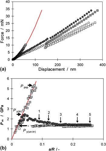
Examples of typical indentation force–displacement curves are shown in Fig. 1(a) for both irradiated and unirradiated material. The unirradiated material is observed to follow the elastic line, indicated by the fully loaded and partially loaded data points falling on the same curve. At relatively high load, a large displacement excursion is seen (pop-in) followed by plastic response recognized as a separation between the fully loaded and partially loaded data points. For the irradiated material, the data is seen to depart smoothly from the elastic line and lie above the unirradiated response in the plastic regime. From each fully loaded and partially loaded data pair, the contact depth, and hence radius of the circle of contact, a, can be determined using the methods detailed in Refs. Reference Zhu, Bushby and Dunstan18 and Reference Field and Swain19. From the calculated values of a for a given load, the indentation stress–strain curve can be generated. The indentation stress is expressed as the mean projected contact pressure Pm = P/πa 2, where P is the applied load. The indentation strain is expressed as a/R, where R is the radius of the indenter tip. Here, R is the calibrated value of the apparent indenter radius for a given measured contact depth rather than the nominal value and this was used to calculate a. Figure 1(b) shows typical indentation stress–strain curves for the irradiated and unirradiated regions of the grain made with the R = 10-μm indenter tip. In almost every case, the unirradiated material displayed prominent ‘pop-in’ behavior. In the indentation stress–strain plot, this behavior is clearly seen as an elastic overload and sudden strain burst, followed by plastic flow at a much lower pressure. About 15% of indents in the unirradiated material remained elastic to high contact pressure (> 8GPa), at the maximum test load. By contrast all of the indents in irradiated material displayed a smooth transition to plastic flow, followed by a decreasing pressure at increasing indentation strain, i.e., strain softening. Only at indentation strains greater than 0.25 was strain hardening evident.
(a) Typical force–displacement curves for irradiated (circles) and unirradiated (squares) samples. The open symbols are the corresponding partially loaded points. (b) Indentation stress–strain curves (mean contact pressure versus contact radius/indenter radius) derived from the partial unloading data for unirradiated (squares), irradiated (circles). The open squares are data from an indent where the pop-in was relatively small. The chain line is a linear regression to the plastic part of the unirradiated material. Arrows with numbers indicate the deformation at which scanning probe microscope (SPM) line traces were taken in Fig 3 below. The solid lines are the expected Hertzian elastic response for a material elastic modulus of 189 GPa. R = 10 μm.

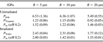
A minimum of 20 indents were made with each of the three indenter tips. Pop-in pressure, P pop, and yield pressure, P Y, were noted for each indent for each indenter radius, as indicated on Fig. 1(b). We define the yield pressure, P Y, as the onset of gross plasticity, requiring significant dislocation multiplication and therefore the unconstrained operation of dislocation sources. In the case of pop-in, the onset of gross plasticity was calculated by projecting the plastic part of the curve to the elastic line, taking the yield pressure to be the intersection of the two lines, as detailed in Ref. Reference Zhu, Bushby and Dunstan18, indicating the pressure at which dislocation sources would operated if they were available. Clearly, it is possible that yield could begin at a higher pressure than this, followed by strain softening as seen in the irradiated regions. However, it is not possible to discern this in cases of exaggerated pop-in. In the rare cases where the pop-in is relatively small, open square symbols in Fig. 1(b), there is no evidence of strain softening, concomitant with tensile testing of irradiated steels.Reference Farrell and Byun11 Values of P pop (unirradiated only), P Y and P m at a/R = 0.2 for each indenter radius are given in Table I.
Mean indentation pressure (GPa) at P pop, P Y and P m at a/R = 0.2 for each indenter radius for both unirradiated and irradiated regions. Numbers in brackets are standard deviations.

For the unirradiated material, the pop-in loads are similar for all indenters but notably the scatter increases with decreasing indenter radius, that is, with decreasing contact size. It is likely that the scatter in pop-in load varies with the extent of the stress field beneath the indenter and results from the paucity of dislocation sources in these highly polished, annealed surfaces. In all cases, the yield pressure, P Y, and flow pressure P m (a/R = 0.2) are much lower than the pop-in pressures and with much reduced scatter, implying that once plasticity is initiated it is highly reproducible. The flow pressure at a/R = 0.2 was found to be always higher for the irradiated material than for the unirradiated material. In indentation experiments covering multiple grains (not reported here) differences in the measured elastic modulus from grain to grain were of the order of +/− 6.5% as might be expected from orientation of different grains.Reference Swadener and Pharr20 Differences in the yield pressures for both irradiated and unirradiated areas from grain to grain were not discernible within the scatter.
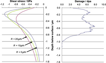
To consider if the yield is initiating wholly within the damage layer in the irradiated material, the Hertzian shear stress profile on the axis beneath center of the indenter τrz(z) was calculated from Hertzian contact mechanicsReference Johnson15 with the contact radius a at yield and the yield pressure P Y as parameters,
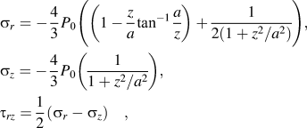
where P 0 is the maximum pressure, equal to 3/2 P m, and with the axial system having z normal to the surface and r radial from the center line. A value of 0.3 is assumed for the Poisson ratio. The resulting shear stress profiles at r = 0 are plotted as a function of depth z in Fig. 2 for the three indenters. The damage profile simulated from the TRIM code is plotted in Fig. 2 on the same scale for comparison. The simulation shows the damage based on the estimated number of vacancies created and the number of recombinations occurring immediately on implantation, rather than the number of defects remaining after an extended time. However, it should provide a reasonable impression of the extent of the affected layer.
TRIM calculated damage as a function of depth (right). Axial Hertzian shear stress at initial yield for irradiated material (left).

The variation in yield pressure with indenter radius reflects the indentation size effect, with the maximum shear stress occurring within the damage layer. Recently it has been shownReference Dunstan, Zhu, Hopkinson and Bushby21 that the yield initiates over a volume centered approximately on the position of the maximum shear stress and it is likely that this volume is mostly contained within the damage layer. Considering the developed plastic zone to be hemispherical in shapeReference Johnson15, Reference Samuels and Mulhearn16 with radius of r p, Feng et al.Reference Feng, Qu, Huang and Nix22 considered the extent of the plastic zone in their embedded center of dilation model and showed that r p∼1.8 a for materials with modulus to hardness ratio of ∼100, i.e., for metals. Applying this model for an indentation strain of a/R = 0.2, the plastic zone would extend a considerable distance below the damage layer. For example, r p = 1.8 μm for the R = 5 μm indenter, r p = 3.6 μm for the R = 10 μm indenter, and r p = 7.2 μm for the R = 20 μm, compared to the depth of the damage layer of ∼0.7 μm. Although the initial yield pressures can be considered to be indicative of the irradiated material, notwithstanding any intrinsic indentation size effect, the strain softening could be substantially attributed to the extension of plasticity into the underlying softer material. The flow stress at higher strains is likely to be dominated by the underlying unirradiated material, hence the similarity in the flow curves above a/R = 0.25. The irradiated material would still be expected to display a slightly higher flow pressure due to the harder surface layer in an analogy of the hard coating on a softer substrate.Reference Bull13 The higher yield pressure in the irradiated material can be attributed to the hardening mechanisms outlined above. However, the absence of pop-in can also be attributed to the inherent defects that can act as dislocation sources.Reference Boudoukha, Halitim, Paletto and Fantozzi7–Reference Roberts and Page10 In ceramic materials subject to ion irradiation the transition to plastic flow is enabled by such mechanisms, reducing the extremely high hardness or eliminating brittle failure mechanisms.
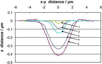
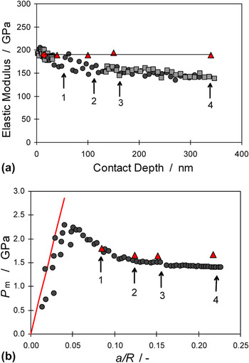
Another consideration is whether the instrumented indentation data is affected by pile-up or sink-in of material around the indentation, resulting in under or overestimation of the contact area, respectively, from the calculated contact depth once plastic flow is initiated. SPM line profiles of indents made with the 10 μm radius indenter at different maximum loads are presented in Fig. 3. The corresponding positions on the flow curve for these 5 profiles are shown on Figs. 1 and 4. It is seen that in the early stages of plasticity the edge of contact (seen as the inflection in the profileReference Hou, Bushby and Jennett23) lies below the surface. This is sink-in, suggesting that the contact area in overestimated, leading to apparently lower mean pressure and elastic modulus. Only after apparent strain hardening, at the highest indentation strains used here does pile-up become apparent. In the case of sink-in, the elastic modulus would be expected to drop after the initiation of plasticity. This is seen in Fig. 4 most strikingly for the unirradiated material where the elastic modulus is seen to drop following the pop-in event (gap in the data with respect to contact depth), while the irradiated material with a smooth transition to plastic flow and gradual sink-in of the indentation contact displays a gradual reduction in modulus. This cannot be due to the underlying pristine material since for contact depths of less than 35 nm, the elastic modulus of the irradiated and unirradiated material is not significantly different (irradiated E = 188 GPa {SD 11.3 GPa}; unirradiated E = 189 GPa {SD 6.41 GPa}) and the unirradiated material is wholly elastic at this depth. Any other differences due to vacancy population or residual stresses are not resolvable by this technique within the measurement uncertainty. Using the actual contact radius from the SPM measurements to calculate the elastic modulus for the first 4 SPM profiles suggests that the elastic modulus is constant with depth, Fig. 4(a), implying that the sink-in completely accounts for the reducing modulus with depth. On the other hand, using the SPM measured contact radius to calculate the mean pressure, Fig. 4(b), shows the sink-in does not account for the apparent strain softening in the irradiated material. It is possible that strain softening is occurring here before the plastic zone reaches the undamaged material. For experiments using a Berkovich indenter, where the indentation strain is considerably higher (a/R = ∼0.6), the indentation response may be more complicated. The initial sharp contact may induce pile-up in the irradiated material at the start followed by softening as the plasticity spreads to the underlying softer materials and returning to further pile-up as the underlying material rapidly hardens under the high contact strain, making the material properties more difficult to interpret.

(a) Indentation elastic modulus as a function of contact depth for unirradiated (squares), irradiated (circles) material. (b) Mean pressure, P m, versus indentation strain, a/R, for a typical indent in the irradiated material. In both (a) and (b) triangles represent the values calculated from the SPM calculated contact area for the first 4 line traces as numbered in Fig. 3. R = 10 μm indenter tip. The diamond in (a) represents the average elastic modulus value for the unirradiated material before pop-in. Solid line in (a) is a linear regression fit to the triangles. Solid line in (b) is the Hertzian elastic line for E = 189 GPa.

IV. CONCLUSIONS
In spherical indentation tests, ion-irradiated Fe12%Cr alloy shows significantly different plasticity behavior to its fully annealed unirradiated state. The presence of irradiation-induced defects raises the initial yield pressure and initiates flow in a smooth transition from elastic deformation. The elastic modulus of the material does not appear to be different between the two conditions within the measurement uncertainty of these experiments. Strain softening of the irradiated material appears likely, as it is observed immediately following the elastic-plastic transition, before significant sink-in and before the plastic zone has extended substantially into the underlying pristine material, at least for the smallest indenter radius used here. At higher plastic strains and greater contact depths, the plastic behavior is similar for irradiated and unirradiated material, particularly for the largest indenter radius where the majority of the plastic zone lies within the underlying unaffected material. These results demonstrate that spherical nanoindentation can reliably determine the yield behavior of materials after irradiation through judicious selection of indenter tip and load combinations.
ACKNOWLEDGMENTS
CDH gratefully acknowledges the provision of Engineering and Physical Sciences Research Council (EPSRC) Industrial Case studentship with the Culham Centre for Fusion Energy, United Kingdom. We thank the staff of the EPSRC National Ion-Beam Facility at the University of Surrey, United Kingdom, for assistance with the ion implantation. Russell Bailey is thanked for assistance with the SPM measurements.