1. INTRODUCTION
Obtaining seamless navigation in all circumstances, including an environment with degraded Global Positioning System (GPS) signals, is a challenging issue. An Inertial Navigation System (INS) can provide continuous navigation information independently but accumulates errors, which need to be corrected frequently by additional measurements. GPS/INS integration has received much attention in navigation applications. Godha and Lachapelle (Reference Godha and Lachapelle2008) proposed a system that combined a shoe-mounted Inertial Measurement Unit (IMU) and GPS to bound drift errors in outdoor scenarios.
For pedestrian navigation in an indoor environment where the GPS signal is unreliable, some non-GPS approaches require external references for tracking and navigation. Hide et al. (Reference Hide, Botterill and Andreotti2010) investigated the use of computer vision-derived velocity measurements to frequently correct the drift of a low-cost IMU. Aoki et al. (Reference Aoki, Schiele and Pentland1999) proposed an image sequence matching technique for the recognition of locations and previously visited places. Work is also being done on simultaneous location and mapping (SLAM), which usually uses cameras as sensors. However, unlike the inertial sensor, these sensors are very sensitive to the environment and are unreliable in unfavourable operating conditions.
Compared to other types of navigation technologies, the main advantages of inertial sensor-based systems are that they are self-contained, environment-independent and can provide continuous navigation information. These meet the requirements of robust pedestrian navigation, not requiring an instrumented, marked, or pre-mapped environment. Meanwhile, the major challenge for IMU navigation alone is how to efficiently reduce the integral drift which is the primary cause of errors in inertial navigation. Whether a pedestrian is walking, running or climbing stairs, there is a stance phase in each step that can provide a zero velocity measurement for error correction of a shoe-mounted IMU. This approach is called zero velocity update (ZUPT). Consequently it is critical to correctly identify the stance phase in each step and then to apply ZUPT for IMU error correction.
Numerous ZUPT-based pedestrian navigation systems have been developed using various approaches for stance phase detection. Foxlin (Reference Foxlin2005) developed a system called NavShoe to use the stance phase of walking as measurements into an extended Kalman filter (EKF) for performing ZUPT. Castaneda and Lamy-Perbal (Reference Castaneda and Lamy-Perbal2010) proposed an improved shoe-mounted inertial navigation system based on the fuzzy logic step detector and an angular updating algorithm. Cho and Park (Reference Cho and Park2006) proposed a pedometer-like approach which counts steps and estimates average length of steps. Step length is estimated from accelerometer readings that are passed through a neural network, and a Kalman filter was used to reduce the effect of magnetic disturbances.
Alternatively, a dead reckoning method of propagating the step length over a certain direction is often used. Huang et al. (Reference Huang, Liao and Zhao2010) proposed a method that fuses both strap-down inertial navigation and pedestrian dead-reckoning methods. Feliz et al. (Reference Feliz, Zalama and García-Bermejo2009) proposed using a compass and gyroscope to determine trajectories and correct sensor measurements, along with an integrated barometer for height measurement. A similar zero-velocity detector constructed around a pressure sensor mounted beneath the heel of a shoe was used with good results (Bebek et al., Reference Bebek, Suster, Rajgopal, Fu, Huang, Çavuşoǧlu and Mastrangelo2010). Jiménez et al. (Reference Jiménez, Seco, Prieto and Guevara2009) implemented and compared several of the most relevant algorithms for step detection, stride length, heading and position estimation. Tests were conducted and it was found that the stride length estimation errors were only about 1%. The positioning errors were almost always below 5% of the total travelled distance. The main source of positioning errors was orientation estimation.
The algorithms for step detection using accelerometers mainly consist of three types: peak detection, zero crossing detection and flat zone detection (Cho et al., Reference Cho, Lee, Park and Lee2003). A gait state is modelled as a Markov process and gait states are estimated using the hidden Markov model filter based on force sensors to determine when to apply ZUPT (Suh and Park, Reference Suh and Park2009). Similarly, a Markov model is constructed using segmentation of gyroscope outputs (Park and Suh, Reference Park and Suh2010). Different step detection algorithms are developed based on both accelerometer and gyroscope outputs. The zero velocity is determined by comparing z-axis accelerometer and y-axis gyroscope outputs with proper threshold values (Yun et al., Reference Yun, Bachmann, Moore and Calusdian2007). Alternatively, the zero velocity is determined based on norms of accelerometer and gyroscope along with variance of the accelerometer. Then a Kalman filter-based framework, called INS-EKF-ZUPT, is implemented (Jiménez et al., Reference Jiménez, Seco, Prieto and Guevara2010). Skog et al. (Reference Skog, Nilsson and Handel2010) developed a novel stance hypothesis optimal detector; however this is restricted to 2D cases. Ojeda and Borenstein (Reference Ojeda and Borenstein2007) implemented two empiric rules for gyro signals analysis to detect zero velocity. The system was tested with a variety of walking patterns, on stairs and on rugged terrain. The horizontal relative error is about 0·49% of the total distance travelled; the vertical error is 1·2%, which might be the highest accuracy in related work.
However, all the step detection algorithms mentioned above only function for walking, and fail to detect stance phases in high-speed movement (running or jumping). Compared with walking, the duration of the stance phase in running is shorter and the velocity in the stance phase is less close to zero velocity. Barely enlarging the threshold will introduce false stance phase detection. It is a challenge to correctly detect stance phases in all the moving styles.
Moreover, none of the shoe-mounted MEMS inertial sensors-based pedestrian navigation systems, using strap-down inertial navigation or pedestrian dead-reckoning methods, can perform well in situations with constant velocity, such as in an elevator or on an escalator. This is due to the fact that they treat stance phases always as zero velocity even if a sensor is not stationary but moving with a constant velocity.
As the errors of estimated position and velocity grow rapidly with time for shoe-mounted MEMS inertial sensors, ZUPT applied at each step leads to sharp corrections of velocity and position; the estimated trajectories have discontinuities and periodic drift, which is unpleasant in accurate navigation and tracking. Colomar and his group (Colomar et al., Reference Colomar, Nilsson and Handel2012) developed an open loop step-wise smoothing algorithm to aid ZUPT that can efficiently eliminate the sharp corrections and discontinuities at the end of the step.
This paper describes our contributions on shoe-mounted inertial sensor navigation on three aspects. We have proposed a robust stance phase detection algorithm to handle both walking and running (Li and Wang, Reference Li and Wang2012). The new algorithm consists of a footstep detector to indicate a new step and a swing phase detector to inform the end of the step, a stance phase detector is applied to detect whether the foot is stationary. As the extension of ZUPT, a new concept called CUPT has been proposed to apply velocity correction when a pedestrian is on an escalator or in an elevator (Li et al., Reference Li, Wang, Xiao and Luo2012). CUPT can broaden the practical use of a shoe-mounted pedestrian navigation system in a building environment. As an improvement of Colomar's open loop step-wise smoothing, a closed-loop step-wise smoothing algorithm is implemented to eliminate the sharp corrections over the steps (Li and Wang, Reference Li and Wang2013).
This paper is organised as follows. Section 2 briefly introduces the general background of a standard strap-down INS mechanism; the framework of ZUPT-aided INS and EKF error model applied in pedestrian navigation. Section 3 presents the stance phase detection for different gait styles, including walking, running and stair climbing. The new concept CUPT for correcting IMU errors on a moving platform with constant velocity is introduced in Section 4 and a closed-loop step-wise smoothing algorithm is introduced in Section 5. Experimental results and discussions are presented in Section 6 and the paper is concluded in Section 7.
2. INERTIAL PEDESTRIAN NAVIGATION
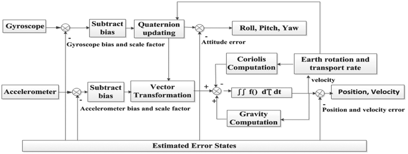
The proposed shoe-mounted inertial navigation system uses only a MEMS IMU, which consists of accelerometers, gyroscopes and magnetometers. The system adopts the standard strap-down inertial navigation mechanization, with zero/constant velocity as the measurement for correction. Figure 1 shows the system mechanization. Attitude can be determined by integration of the rotation rate of gyros. After vector transformation, velocity and position can be determined by the integration of acceleration with compensation of gravity and Coriolis force. If no estimated error states (EES) provide correcting information however, due to the bias of the sensors and the noise associated with the measurement, this simple integration in practice leads to unbounded growth in position errors with time.
The basic blocks of strap-down inertial navigation mechanization.

2.1. ZUPT/CUPT
In order to obtain a high accuracy navigation solution with a shoe-mounted IMU, ZUPT/CUPT can be applied to reduce the errors. They use the fact that when a pedestrian travels, one's feet alternate between a stance phase and a swing phase. If the stance phase appearing in each step can be detected correctly at a known (zero or constant) velocity, the INS velocity errors can be corrected periodically. More detailed explanation about ZUPT/CUPT can be found in Foxlin (Reference Foxlin2005) and Li et al. (Reference Li, Wang, Xiao and Luo2012).
It is important to correctly identify the stance phases of the IMU attached to a shoe and then apply ZUPT/CUPT to bind the navigation errors by providing proper EES (see Figure 1) with EKF or other estimation algorithms. There are two types of error in stance phase detection: misdetection and false-detection. It is noticed that a stance phase misdetection causes less serious problems for navigation accuracy than a false-detection. A misdetection just misses a chance for INS correction while a false-detection results in a wrong ‘correction’ and may cause the navigation results to become useless.
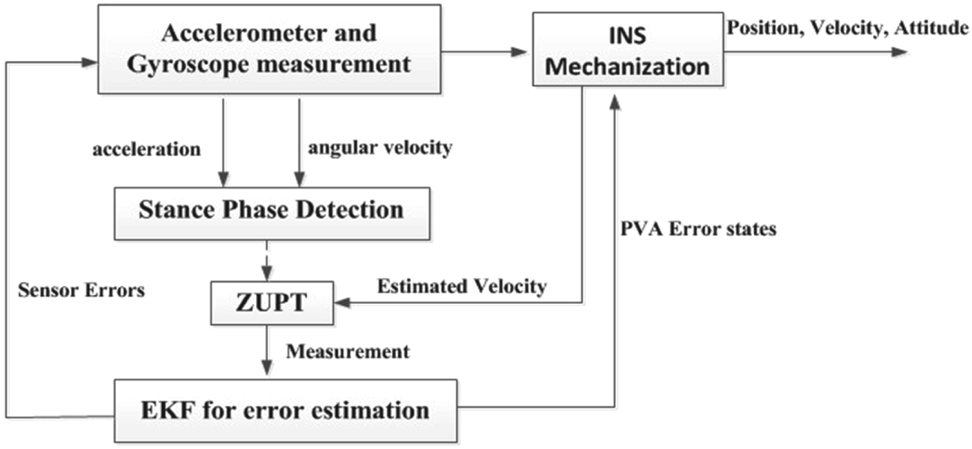
In order to get a high accuracy navigation solution, ZUPT/CUPT is applied with an EKF to reduce navigation errors. The framework of the proposed navigation system is illustrated in Figure 2. It has three main blocks: 1) INS Mechanization to compute the position, velocity and attitude; 2) Stance Phase Detection block to determine stance phases and apply ZUPT/ CUPT; 3) EKF block to estimate the error states and bound navigation errors.
The main blocks in the framework used for pedestrian inertial navigation.
2.2. EKF
The EKF we used consists of 24 error states including navigation errors, sensor errors and gravity uncertainty. In each estimation cycle, once zero velocity has been detected, ZUPT delivers the updated error states to INS, the navigation error states are reset to zero after the current position, velocity and attitude is corrected. Other error states are accumulated and fed back to the inertial navigation mechanization.
The EKF includes the following 24 error states:
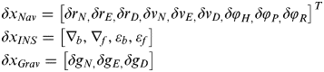 $$\eqalign{ & \delta x_{Nav} = \left[ {\delta r_{N,} \delta r_{E,} \delta r_{D,} \delta v_{N,} \delta v_{E,} \delta v_{D,} \delta \varphi _{H,} \delta \varphi _{P,} \delta \varphi _R} \right]^T \cr & \delta x_{INS} = \left[ {\nabla _b, \nabla _f, \varepsilon _b, \varepsilon _f} \right] \cr & \delta x_{Grav} = \left[ {\delta g_{N,} \delta g_{E,} \delta g_D} \right]} $$
where δ x Navδ x INS and δ x Grav are the navigation error vector, the IMU sensor measurement error vector and gravity uncertainty respectively. δ r δ v and δ φ are the position, velocity and attitude error vectors. ∇ expresses the accelerometer error vector, and ε is the gyro error vector. Subscript b stands for bias and subscript f stands for scale factor.
The Psi-angle INS error model is adopted in the system (Grejner-Brzezinska et al., Reference Grejner-Brzezinska, Toth and Yi2001):
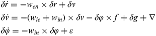 $$\eqalign{ & \delta \dot r = - w_{en} \times \delta r + \delta v \cr & \delta \dot v = - (w_{ie} + w_{in} ) \times \delta v - \delta \varphi \times f + \delta g + \nabla \cr & \delta \dot \varphi = - w_{in} \times \delta \varphi + \varepsilon} $$
where δr δv δφ are the position, velocity, and attitude error vectors respectively, ∇ is the accelerometer error vector, δg is the error in the computed gravity vector, ε is the gyro error vector, f is the specific force vector, w ie is the earth rotation rate vector, w en is the transport rate vector and w in is the angular rate vector from the navigation to the inertial frame. The dynamic matrix is obtained by a linearization of Equation (2).
 $$\left[ {\matrix{ {\delta \dot x_{Nav}^{1 \times 9}} \cr {\delta \dot x_{grav}^{1 \times 3}} \cr {\delta \dot x_{IMU}^{1 \times 12}} \cr}} \right] = \left[ {\matrix{ {F_{11}^{9 \times 9}} & {F_{12}^{3 \times 9}} & {F_{13}^{12 \times 9}} \cr {0^{9 \times 3}} & {F_{22}^{3 \times 3}} & {0^{12 \times 3}} \cr {0^{9 \times 12}} & {0^{3 \times 12}} & {0^{12 \times 12}} \cr}} \right] = \left[ \matrix{\delta x_{Nav} \cr \delta x_{grav} \cr \delta x_{IMU} } \right] + \left[ \matrix{w_{Nav} \cr w_{grav} \cr w_{IMU} } \right]$$
where w NavwIMU and w grav are all zero-mean Gaussian white noise vectors. A detailed expression of the dynamic matrix can be found in Grejner-Brzezinska et al. (Reference Grejner-Brzezinska, Toth and Yi2001).
For ZUPT/CUPT, the observation z 1×3 is the velocity vector in three directions, and the measurement model is:
 $$z = H\delta x + {\rm n}$$
where H3×24 = [O 3×3I 3×3O 3×3] and n is the measurement noise vector.
Consider the error state  ${\rm \;} \delta x = \; \hat x - x$ where
 $\hat x$ is the estimated state and x is the true state, the observation z is
 $\hat x - 0$ for ZUPT and
 $\hat x - v_c $ or CUPT, where
 $\hat x$ is computed by the strap-down inertial navigation mechanization and v c is the constant velocity.
In addition to pursuing reliable observation to improve an EKF's estimation, as we are doing here, some other approaches are also conducted, such as the quantization and coloured noises error modelling for inertial sensors (Han and Wang, Reference Han and Wang2011), and adaptive EKF (Wang et al., Reference Wang, Ding and Wang2007). This paper's scope only covers the approaches for obtaining reliable observation with ZUPT/CUPT.
2.3. Stance Phase Detection
The stance phase detector we proposed consists of the following four logical conditions C1-C4, using both the accelerometer and gyro measurements. These four conditions must be satisfied (=1) simultaneously to declare a foot as stationary for every sample epoch k.
1) The magnitude of the acceleration |a k| where a xkayk azk are the magnitude of the acceleration on x, y, z-axis respectively:
(5a) $$\eqalign{& |a_k | = [a_{xk}^2 + a_{yk}^2 + a_{zk}^2 ]^{1/2} \cr & C1 = \left\{ {\matrix{ 1 & {threshold_{amin} \lt |a_k | \lt threshold_{amax}} \cr 0 & {otherwise} \cr}} \right.} $$
2) The magnitude of the acceleration on z-axis |a zk|:
(5b)$$C2 = \left\{ {\matrix{ 1 & {threshold_{azmin} \lt \left| {a_{zk}} \right| \lt threshold_{azmax}} \cr 0 & {otherwise} \cr}} \right.{\rm \; \; \;} $$3) The magnitude of the angular velocity |w k|:
(5c)$$\eqalign{& |w_k | = [w_{xk}^2 + w_{yk}^2 + w_{zk}^2 ]^{1/2} \cr & C3 = \left\{ {\matrix{ 1 & {|w_{yk} | \lt threshold_{wmax}} \cr 0 & {otherwise} \cr}} \right.{\rm \; \; \;}} $$4) The magnitude of the angular velocity on y-axis |w yk|:
(5d)$$C4 = \left\{ {\matrix{ 1 & {|w_{yk} | \lt threshold_{ywmax}} \cr 0 & {otherwise} \cr}} \right.{\rm \; \; \;} $$
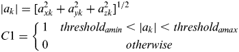

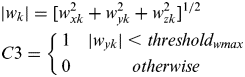

Since a foot firmly contacts the ground in a stance phase, the acceleration and rotation of the foot is zero over this duration. In an ideal condition the magnitude of total angular velocity |w k| in Equation (5c) and acceleration in a horizontal plane should be zero during a stance phase. However, the actual measurements are not zero due to vibration and the sensors' bias, but are still lower than the given thresholds.
By observing the outputs of a shoe-mounted IMU, it is found that the z-axis acceleration a zk and the y-axis angular velocity w yk are the most significant indicators in pedestrian travel. Due to the tilt of a shoe's surface, however, the measured |w yk| and |a zk| are not exactly 0 and g respectively. So the thresholds in Equations (5b) and (5d) are set based on the average value of z-axis accelerometer and y-axis gyro outputs during an initial stationary period, plus a certain level of fluctuation to ensure its robustness. The initial stationary period is at the beginning of sensor data collection when the shoe-mounted IMU is in a stationary condition.
2.4. Height Constraint
Similar to the concept proposed by Abdulrahim et al. (Reference Abdulrahim, Hide, Moore and Hill2012), we assume that the changes in height are only caused by climbing stairs since the floor is level in most indoor environments. If a change in height over one step is above a threshold, we regard it as reaching a new level or a stair; otherwise the height will be maintained at the previous level and uses this as a measurement of the Kalman filter. This constraint works well in structured environments with only level floor and stairs, but fails in the case of gently sloping terrains.
3. RUNNING
A stance phase detector for walking is incapable of detecting the stance phase correctly for running since the duration of the stance phase in running is shorter, and the stance phase is less stable as zero velocity. Barely enlarging the detection thresholds will introduce false stance phase detection.
In addition to developing a robust stance phase detector for walking and climbing as described in Section 2.3, we have also proposed a new detector for running. It includes a footstep detector that is used to determine the beginning of the gait cycle; a swing phase detector to indicate the swing phase of the step and zero velocity detectors that are used to detect the stance phase before the swing phase. The swing phase detector is used to avoid false detection during swing phase especially when the foot is nearly leaving the ground.
3.1. Footstep Detector
In pedestrian navigation with a shoe-mounted IMU, especially for running, it is important to know when a pedestrian takes a step. A footstep detector can not only mark the beginning of a gait cycle, but also helps to segment the pedestrian's gait cycle into four phases: stance, heel-off, swing, heel strike. A footstep detector mainly detects the heel strike after a foot completes swing phase in the air, reaches the highest point and touches down on the ground. Once the heel has hit the ground, the deceleration of the forefoot is very dramatic and characterised by large changes in the acceleration profile. Thus, we simplify the characteristic thus: in heel strike phase, the z-axis acceleration experiences a monotonic decreasing that is unique and obvious to detect so we denote it as a new step.
3.2. Swing Phase Detector
A swing phase detector is designed to identify swing phases and prevent false stance phase detection in swing phases when enlarging the thresholds of the stance phase detector for the running case. The swing phase detector introduced here is based on the energy of rotation threshold T S.  $y_k^g $ is the angular velocity at the time instant k, W is the window size. The swing phase detector is combined with the footstep detector to separate a swing phase from other phases. As swing phases are identified, false stance phase detection in swing phases can be avoided.
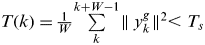 $$T(k) = \textstyle{1 \over W}\sum \limits_{k}^{k + W - 1}}\hskip-2pt \parallel y_k^g\hskip-2pt \parallel ^2 \lt T_s $$
Figure 3 shows the energy of rotation T in two gait cycles. It should be noted that the footstep detector can also use this T to detect heel strikes. The energy of rotation goes through a big jump when the foot falls down to the ground, as Figure 3 indicates.
The energy of rotation T.
4. CUPT
As mentioned by Abdulrahim et al. (Reference Abdulrahim, Hide, Moore and Hill2012), ZUPT will fail in two situations such as on an elevator or escalator. This is due to the fact that the stance phases detected on a moving platform are not zero velocity. If a ZUPT algorithm is applied to a moving platform, it will regard the moving platform as having zero velocity and perform ZUPT. As a result, the navigation solution is obviously wrong. Use of other sensors or additional measurements may help to address these issues, but it will be complex and costly. Without additional sensors, we have proposed a CUPT algorithm that uses constant velocity as the additional measurement.
ZUPT is just a special case in CUPT where the true velocity in the stance phases is zero. CUPT can detect the stance phases as ZUPT when stepping on the ground, and also a constant velocity when the pedestrian is standing in a moving elevator or on an escalator.
The core concept of the CUPT algorithm is to detect the velocity of a platform instead of assuming it as zero as in ZUPT. Obviously, the stance phase detection on a moving platform is exactly the same as the stance phase detection on the ground without considering a platform velocity. However, CUPT needs not only to identify a stance phase, but also to measure the velocity of the moving platform and decide whether the velocity is constant or not.
4.1. Elevator
Taking an elevator as example, Figure 4 shows the measurement of the vertical accelerometer AccZ and the estimated velocity. A pedestrian walked into the elevator and stood still when the elevator was moving. As indicated by the velocity in Figure 4, the elevator went through a period of acceleration, kept at constant velocity and decelerated before it was stationary again. The constant velocity appears once the elevator finishes accelerating and before the elevator starts slowing down. In this circumstance, the most significant indicator is the acceleration in the vertical direction.
Indication of motion in an elevator.
When the elevator starts to move, the acceleration in the z-axis experiences a jump which can be easily distinguished from the normal gaits. When this special case of acceleration has been detected, the velocity is calculated by the inertial navigation algorithm without a velocity measurement update. Since the pedestrian stands in the elevator, the zero horizontal velocity can be added as a measurement to the EKF, referencing to Equation (4):
 $$z = \hat x - v_{XY} $$
After the elevator finishes accelerating, the velocity keeps constant before the elevator begins to slow down. During this constant velocity section, CUPT is applied to correct navigation errors. So the measurement z is  $\hat x - v_{constant} $. The decelerating section is similar to the accelerating section, and the zero horizontal velocity update is applied.
During the accelerating and decelerating sections, elevator data processing follows the INS mechanization to obtain position, velocity and attitude information without any velocity update until a constant velocity is detected. However, in some cases it is hard to detect constant velocity. The motion in accelerating and decelerating sections actually has a variable acceleration rate. Especially during braking, an elevator first slows down to a low speed, then keeps at this low constant velocity for a while, before decelerating to zero velocity. As a result, frequent elevator stops have an influence on the accuracy of height measurement.
4.2. Escalator
For the case of being on an escalator, the horizontal velocity is the most significant indicator. When a foot steps onto the escalator and keeps pace with the escalator going up or down, a constant velocity is determined by the instance of the foot being set on the escalator. So in this case, the measurement z is  $\hat x - v_{constant} $. Once the horizontal velocity is over a threshold in stance phase, it is assumed that the foot is on an escalator and we apply CUPT as measurement of the EKF.
Figure 5 shows the horizontal and vertical velocity of a foot on a moving escalator. We can see that ZUPT is applied when the pedestrian walks on the ground; the observation is zero velocity during the stance phase, while the velocity keeps constant when the pedestrian stands on the escalator and CUPT corrects the velocity error using the constant velocity as the observation.
Motion in an escalator with CUPT.
In summary, the stance phase detection for CUPT is the same with ZUPT since the foot is statically in contact with a platform in both cases. But for CUPT the velocity of the moving platform needs to be measured. ZUPT is applied when a person is walking on the ground while CUPT is to handle the case on a moving platform. In order to apply CUPT, firstly we need to use the stance phase detector to declare whether the foot is stationary, then determine whether the foot is on a moving platform, measure the constant velocity of the platform and apply CUPT to correct the errors.
5. SMOOTHING
Smoothing uses the fact that the sensor data can also be used in a reverse time fashion. The goal of smoothing is to determine an optimal estimate utilizing information before and after the current time. This paper introduces a closed-loop step-wise smoothing algorithm based on a Rauch-Tung-Striebel (RTS) smoother.
5.1. RTS Smoother
The RTS smoother is a two-pass smoothing algorithm. The forward pass is the same as the regular Kalman filter algorithm. During the prediction and update steps, the states and covariance are saved for use in the backwards pass. After the forward pass, the RTS smoothing begins from the end of the mission and moves back to the starting point of the data set. In the backwards pass, the smoothed state estimates and covariance propagate using the states saved in the forward pass (Rauch et al., Reference Rauch, Striebel and Tung1965). The smoothed estimate of the states is computed using the equations below.
 $$\hat x_{k|N} = \hat x_{k|k} + C_k [(\hat x_{k + 1|N} - \hat x_{k + 1|k} ]$$
 $$P_{k|N} = P_{k|k} + C_k (P_{k + 1|N} - P_{k + 1|k} )C_k {\rm '}$$
where  $C_k = P_{k|k} \O ^{'\left( {k + 1,k} \right)P_{k + 1|k} ^{ - 1}}, \; \hat x_{k|k}, \; \hat x_{k + 1|k}, \; P_{k|k}, \; P_{k + 1|k} $ are the error states and their variances stored in the forward filter.
5.2. Data Segmentation
The implementation of the RTS smoother has some limitations. Firstly, it is commonly applied for post processing. Secondly, a lot of memory is required to store the predicted and updated information (Chiang et al., Reference Chiang, Duong, Liao, Lai, Chang, Cai and Huang2012). In order to achieve near-real-time smoothing and reduce the storage burden, one intuitive way is to take profit of the detected zero velocity intervals and divide the step with them.
In order to get near-real-time smoothing, proper segmentation rules should be applied. The principle for our data segmentation is similar to the one proposed by Colomar et al. (Reference Colomar, Nilsson and Handel2012). They use velocity error covariance as a threshold. The choice of the threshold value is based on typical values from the training data of random walking, so it is not suitable for scenarios that involve running. Moreover, it is not applicable for navigation on a moving platform, such as elevator or escalator, where the velocity of a foot in stance phase may not converge to zero but a constant velocity. In addition, the fixed time constant of 30 samples that they applied may work properly in normal walking but fail occasionally in running, since the duration of stance phase in running may be shorter than 30 samples and it will cause misdetection. Furthermore, if the person alternates between walking and running, the segmentation rule based on velocity error covariance will easily get confused and become invalid.
We proposed a new segmentation rule by combining both the footstep detector and swing phase detector. The energy of rotation threshold T is used to avoid false segmentation in swing phases, which makes the rule more flexible to meet the complex environment.
The segmentation point should be in the stance phase. Here we have tried three methods to get the segmentation point; the first one is to use the middle point of the stance phase, the second one is the sample point with smallest T during the stance phase and the third one is the sample point with T under a certain small threshold. According to our tests, these three methods have little difference in the final smoothing results, which means that we do not need to find where the exact point converges to zero, as long as the segmentation point is within the stance phase. The third method is used as the segmentation rule in the following closed-loop smoothing.
5.3. Closed-Loop Smoothing
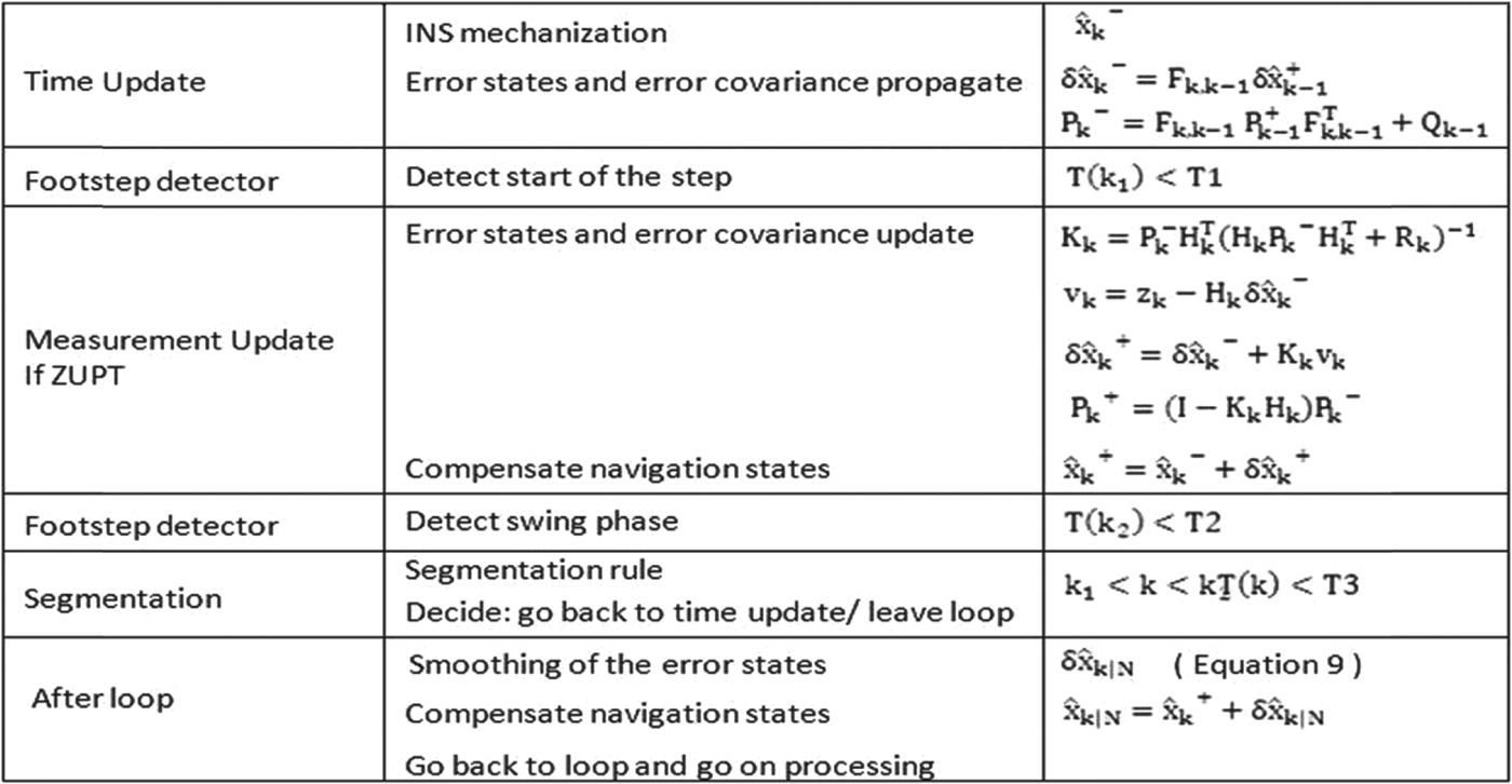
In our ZUPT-aided INS implementation, the predicted EKF error states are always reset to zero. During measurement updates, the estimated error states are corrected and fed back to compensate the estimated navigation states. However, in a closed-loop smoothing-aided ZUPT, the EKF runs as normal but the predicted error states need to be propagated and no longer reset to zero. The estimated states and covariance are updated only when ZUPT are applied and the smoothing is applied over the error states. After the step segmentation is performed, the estimated states are combined with the smoothed error states to get the final navigation results. Figure 6 summarises the implementation procedures for the closed-loop smoothing.
Step wise close loop smoothed ZUPT aided INS.
6. EXPERIMENTS
The proposed pedestrian navigation system has been tested for walking, running, stair climbing and taking an elevator or escalator.
6.1. Hardware Description
We implemented our pedestrian navigation system with the Navchip IMU from Intersense. The small size of Navchip makes it easy to attach to a boot and has no effect on walking. Table 1 lists the specification of Navchip (encapsulated within casing).
Specification of Navchip IMU.

6.2. Walking and Running Test
6.2.1. Experimental data processed results
All the trajectories are closed-loop with the finish point the same as the start point. Since the start and stop points are the exact same location in reality, the distance between the black and blue dots in the below figures represents the error on the horizontal plane. Figure 7 represents three trajectories including stair climbing.
(a) 3D trajectory 1, (b) 3D for trajectory 2 and (c) 3D trajectory 3.
(a) Trajectory 1 and (b) Trajectory 2.
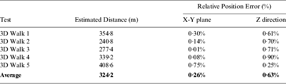
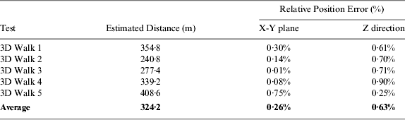
Table 2 shows the final return position errors for three-dimensional (3D) experiments.
Return Position Errors.
In this section we present two trajectories (Figure 8) and each trajectory is traversed several times with different human gaits that include walking, running and alternating between walking and running. All the trajectories are closed-loop.
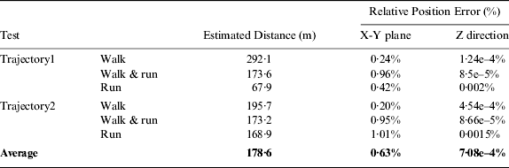
Table 3 summarises the final return position errors for each trajectory and Table 4 also gives the comparison results of different gait styles.
Return Position Errors.

Errors of Different Gait styles.

Ideally the error of running should be larger than that of alternating between walking and running, since the higher dynamics experienced during running than in walking result in fewer ZUPT applications. However, from our results as shown in Table 4, we get a different conclusion. The main reason is that when the pedestrian changes his gait randomly, sometimes it is easy to confuse the footstep detector. On the other hand, the swing phase detector is applied to ensure that no false stance phase detection in swing phases, thus we can still get reasonable results.
In addition, out of the excessive shock of feet strikes, the bi-directional overflows exceed the ranges of accelerometer and/or gyroscope and will affect navigation accuracy to a large extent. Although we have already taken measures to reduce the impact, it is still inevitable that the overflow would affect the INS mechanism computing vertical velocity and position.
6.2.2. Reference data processed results
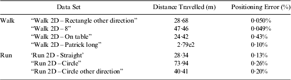
In this section, we also give the results by processing the reference dataset provided in Angermann et al. (Reference Angermann, Robertson, Kemptner and Khider2010). In their paper, the authors also give the processed results using two customary methods that fail when processing the running data. Table 5 shows the distance travelled error normalized to the total distance travelled.
6.3. Elevator and Escalator Test
This section describes elevator and escalator tests conducted in the UTS tower building.
6.3.1. Elevator test
The pedestrian walked for a while before going into an elevator. The pedestrian randomly chose which elevator to take and which level to stop at. When the door was closed, the pedestrian stopped walking and stayed still until the door opened again.
Three trajectories are shown in Figure 9. The left figure is the 3D view of the trajectory while the right figure represents the height change over time shown by the red line. The black dots in the right figures indicate the sample points have been applied CUPT in the slope sections with a constant velocity, or ZUPT in the flat sections. It is noticed that only a few small sections of the red line in the right figures are not covered by the black dots, which are the periods that the elevator is accelerating or decelerating where neither ZUPT nor CUPT can be applied for vertical position and speed correction.
(a) Trajectory 1 of elevator test, (b) Trajectory 2 of elevator test and (c) Trajectory 3 of elevator test.
6.3.2. Escalator test
Tests were also conducted for an escalator. As shown in Figure 10, starting at a lower level, the pedestrian walked for a while and then stood on a rising escalator with the IMU mounted on one foot. After getting off the escalator at the middle level the pedestrian walked to another rising escalator to the top level; and then walked to the two falling escalators in sequence to descend back to the start point.
Trajectory of escalator test.
Distance-Travelled Errors Normalized to the Total Distance Travelled.
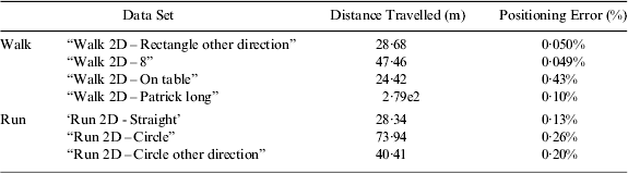
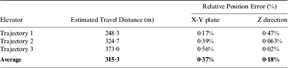
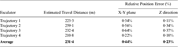
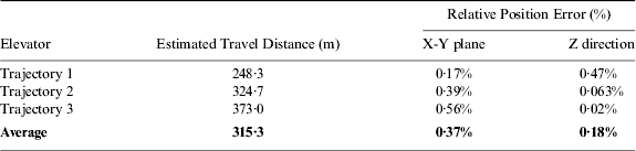
Figure 10 is the 3D view of the trajectory, which clearly represents the four escalators and the three levels walked. Tables 6 and 7 summarise the return position errors for elevator and escalator experiments respectively.
Return Position Errors for Elevator.
Return Position Errors for Escalator.
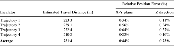
Although these test results are reasonably good, there is still plenty of room to further improve the proposed algorithm to achieve better performance and handle more challenging situations. For the escalator, the vertical angle of the escalators was predetermined to compute the vertical velocity. This angle could be measured by the sensor with more sophisticated investigation. Although the height relative error in Table 7 is small, the horizontal relative error is not so good. This may be due to the change in the vertical angle at the two end sections of escalators where the staircase keeps moving forward but does not change in the vertical direction. The predetermined slope angle introduces error for the measurement update in the short end sections.
6.4. Smoothing Results
All experimental tests have been conducted in UTS, including walking, running and taking escalator and elevator. The figures below show the achieved smoothing effect compared with the estimated trajectory.
Figures 11 and 12 show the effect of smoothing over a walking and running trajectory respectively. From the height and velocity analysis, we can see that when the first ZUPT is applied, the correction applied over the estimated trajectory results in a big jump appearing in every step. After smoothing, these big jumps can be eliminated thus the trajectory is smoother than the original one.
Effect of smoothing on a walking trajectory.
Effect of smoothing on a running trajectory.
Effect of smoothing on an elevator trajectory.
Effect of smoothing on an escalator trajectory.
Compared with walking, the magnitude of running velocity may vary and not converge to exactly zero as walking does during the stance phase.
For the cases in an elevator and on an escalator, CUPT is applied to let velocity not converge to zero as ZUPT, but to a constant velocity when the pedestrian stands on the moving platform. It is also obvious to see that the smoothing algorithm can significantly improve the smoothness of the trajectory especially when the elevator finishes accelerating or decelerating and the pedestrian gets on or off the escalator (Figures 13 and 14).
7. CONCLUSION
In this paper, we have documented a robust pedestrian navigation system that can not only detect the stance phase for running, but also give the navigation solution when the pedestrian is in an elevator and on an escalator. Based on the RTS smoother, we also proposed a closed-loop step-wise smoothing to eliminate the sharp correction and discontinuity of the trajectory.
This paper presented a self-contained pedestrian navigation system that could work in both 2D and 3D environments with good performance. For 3D stairs climbing experiments, the average final return position error on the horizontal plane is around 0·26% of distance travelled, the height drift is about 0·63%, while the final return position error for 2D walking is even smaller, that is 0·16% on X-Y plane by average and we can always get back to the original position for each loop with an average error of 0·33%.
The proposed pedestrian navigation system can also handle running cases. From the test results, we can draw a conclusion that the algorithm is efficient to limit the growth of IMU error. Our robust stance phase detection shows satisfactory performance.
In addition, this paper presents a CUPT algorithm that works on a moving platform with good performance. For elevator experiments, the average return position error on the horizontal plane is around 0·37% of the total distance travelled; the height drift is about 0·18%. The return position error for an escalator is a little larger, that is 0·44% in the horizontal plane by average and 0·23% in the vertical.
Future work will attempt to address several aspects of the navigation system. Firstly, more specific mathematical models will be analysed for the elevator and escalator tests. Secondly, augmentation with other sensors will be explored, such as using a magnetometer to improve the navigation accuracy. Finally, the feasibility of integration with GPS and a camera will be tested. This multi-sensor integration will make the pedestrian navigation system meet more complex environments and thus broadening the practical use.