




1. Introduction
Vortex rings in dense suspensions are ubiquitous across many biological and engineering systems. For instance, the presence of a vortex ring within the left ventricle and its effect on cardiovascular function, including rapid blood filling, has received much attention (Pierrakos & Vlachos Reference Pierrakos and Vlachos2006; Kheradvar & Gharib Reference Kheradvar and Gharib2009; Töger et al. Reference Töger, Kanski, Carlsson, Kovács, Söderlind, Arheden and Heiberg2012). However, little is known about the behaviour of vortex rings in dense suspensions, where, for instance, previous studies have assumed blood to be a single-phase fluid despite being comprised of 40 %–50 % suspended red blood cells (Vlachopoulos, O'Rourke & Nichols Reference Vlachopoulos, O'Rourke and Nichols2011).
Characterizing the behaviour of dense suspensions is challenging since their dynamics is influenced by the interactions and lubrication between suspended particles. Early studies were limited to laminar flows and focused on rheological properties, including shear thinning or thickening, as well as jamming in high volume fractions (as reviewed in Stickel & Powell (Reference Stickel and Powell2005)). Flows in suspensions have been assumed to act as a continuum in which their dynamics is described by an effective viscosity, where several semiempirical formulas were reported to relate the effective viscosity to the volume fraction of a suspension (Chang & Powell Reference Chang and Powell1994; Gillies & Shook Reference Gillies and Shook2000; Stickel & Powell Reference Stickel and Powell2005). More recently, Guazzelli & Pouliquen (Reference Guazzelli and Pouliquen2018) have presented a review centred on the rheology of dense suspensions of non-colloidal particles, including semiempirical formulas that have emerged since Stickel & Powell (Reference Stickel and Powell2005). Nevertheless, suspensions cannot be reduced to a simply effective fluid when the fluid and suspended particles experience relative motion with one another. Bagnold (Reference Bagnold1954) found that the effective viscosity increases linearly with the shear rate in the macroviscous regime (Bagnold number less than 40). Picano et al. (Reference Picano, Breugem, Mitra and Brandt2013) used the particle Reynolds number as the non-dimensional form of shear rate and showed that shear thickening can be induced when the inertia of the suspended particle is sufficiently high. This latter effect demonstrates that the effective viscosity is a function of both the suspension volume fraction and the particle Reynolds number. Lashgari et al. (Reference Lashgari, Picano, Breugem and Brandt2014) further reported that inertial shear-thickening only takes place for finite particle Reynolds numbers (i.e.  $Re_p>0$, as described in Stickel & Powell (Reference Stickel and Powell2005) and Kulkarni & Morris (Reference Kulkarni and Morris2008)). More recently, Picano, Breugem & Brandt (Reference Picano, Breugem and Brandt2015) conducted fully resolved direct numerical simulations of turbulent flows in dense suspensions with neutrally buoyant spheres using an immersed boundary method. This method can simulate a suspension with a particle number of
 ${O}(1000)$ with a finite particle size, which means that the particles are larger than the smallest scales in the flow but smaller than the size of the macroscopic flow structures. Particle inertia plays an important role in this regime, and the work completed by Costa et al. (Reference Costa, Picano, Brandt and Breugem2016) revealed that the suspension could deviate from the continuum limit in a particle-wall layer, where the slip velocity is significant. More recent experimental research has also demonstrated that large particles (particle diameter of O(1 cm)) generate significant deviations from the continuum limit, and the effective viscosity is not sufficient to determine the flow behaviour of such suspensions (Zade et al. Reference Zade, Costa, Fornari, Lundell and Brandt2018; Baker & Coletti Reference Baker and Coletti2019).
Although the effects of suspended particles on the rheological behaviour of dense suspensions in laminar flows, and their modifications in turbulent flows, have been extensively investigated, the interactions between the suspended particles and coherent structures have received far less attention. Furthermore, our understanding of the mechanisms of vortex-ring formation and evolution in past decades has been limited to single-phase fluids (Auerbach Reference Auerbach1987; Gharib, Rambod & Shariff Reference Gharib, Rambod and Shariff1998; Krueger & Gharib Reference Krueger and Gharib2003; Dabiri Reference Dabiri2009). Palacios-Morales & Zenit (Reference Palacios-Morales and Zenit2013) investigated vortex-ring formation at Reynolds numbers of  ${O}(100)$ and showed that a decreasing Reynolds number corresponds to an increasing value of the non-dimensional vortex-core radius (a parameter developed by Norbury (Reference Norbury1973)). This causes vortex-ring pinch-off to be postponed to a stroke ratio of approximately 6, and the resultant vortex rings are elongated and compressed. This vortex-ring elongation and compression phenomenon is also observed in the post formation stage (Danaila & Helie Reference Danaila and Helie2008) and in confined domains (Stewart & Vlachos Reference Stewart and Vlachos2012). These previous studies have revealed much about the mechanics of vortex rings in single-phase fluids, as well as the influence of the confinement ratio and Reynolds number on their dynamics during their formation and evolution. However, to date, no research has considered the influence of suspended particles on the vortex-ring dynamics in dense suspensions, which is considered as a canonical case to study the interactions between suspended particles and coherent structures.
The objective of the current study is to elucidate the influence of suspended particles on vortex-ring dynamics in suspensions with volume fractions up to  $\Phi =20\,\%$ in both unconfined and confined cases. Additionally, we compare the dynamics of vortex rings in dense suspensions with those formed in pure water at low Reynolds numbers (Palacios-Morales & Zenit Reference Palacios-Morales and Zenit2013), since the effective viscosity typically increases in suspensions. We implement refractive index matched hydrogel particles to produce optically transparent suspensions (Zhang & Rival Reference Zhang and Rival2018), which enables the use of time-resolved particle image velocimetry (PIV) measurements to quantify the velocity and vorticity fields of the liquid phase. This method has also been successfully applied to measure the solid and liquid phases of confined vortex rings simultaneously in suspensions using shake-the-box measurement techniques (Zhang, Jeronimo & Rival Reference Zhang, Jeronimo and Rival2019). The vortex rings are generated with a classic piston-cylinder configuration, as shown in figure 1. The resultant measurements are then used to compute the dynamical and topological characteristics of vortex rings, including the non-dimensional vortex-core radius, maximum vorticity, and vortex-ring circulation in pure water, dilute suspensions and dense suspensions. The influence of confinement is then investigated to reveal how it affects the dynamics of vortex rings in dense suspensions. Details of the experimental methodology are described in § 2, results and discussion of the dynamics of unconfined and confined vortex rings are reported in § 3 and the main findings of the study are then discussed in § 4.
Classic vortex-ring formation via a piston-cylinder mechanism. A piston moves at a constant speed ( $U_c$) through the piston cylinder (
 $D_0$), which is in turn confined by the outer cylinder (
 $D$). The vortex ring is characterized by the non-dimensional vortex-core radius (
 $\alpha =r/R$). The elliptical vortex core is described using two length scales
 $r_1$ and
 $r_2$, and represent the vortex-core half-spacing in the radial and streamwise directions, respectively.

2. Experiment set-up
The following section outlines the experimental methods used in this study to quantify the particle–vortex interactions in dense suspensions. The methodology of obtaining an optically transparent suspension is first presented, followed by a description of the experimental apparatus and test parameters. Finally, the equipment, specifications and methodology used to obtain the planar time-resolved PIV measurements are described in detail.
2.1. Optically transparent suspension
In this study, experiments were performed in pure water ( $\Phi =0\,\%$), dilute suspensions (
 $\Phi =2\,\%$) and dense suspensions (
 $\Phi =20\,\%$). Here, ‘dense’ refers to the situation where the average separation distance between particles is smaller than that of the particle size itself. The suspensions were rendered optically transparent using a refractive index matching technique, which implemented hydrogel particles made of a superabsorbent polymer material with a water absorption coefficient of
 $450\ {g}_{water}/g_{polymer}$. When fully saturated, the hydrogel particles matched the refractive index and density of pure water. The solid particles were uniformly dispersed in the suspension, and the mean particle diameter,
 $d_p$, ranged between 0.8–1.4 mm. The settling velocity of the particles was measured to be approximately
 $V_s=0.6 \pm 0.3\ \textrm {mm}\ \textrm {s}^{-1}$ (
 $\text {mean}\pm \text {one standard deviation}$).
2.2. Experimental apparatus and test parameters
As shown in figure 2, vortex rings in unconfined and confined cases were generated by a traverse system that actuated a piston-cylinder mechanism of diameter  $D_0=38$ mm within a concentric Plexiglas tube of diameters
 $D=152$ mm and 76 mm for the unconfined and confined cases, respectively. The corresponding ratio between the particle diameter and piston-cylinder diameter was estimated to be
 $d_p/D_0\sim 1/38$. The piston cylinder was moved at constant speeds of
 $U_c=0.02\text {--}0.32\ \textrm {m}\ \textrm {s}^{-1}$ over a range of distances. The large confining tubes were 457 mm long (12
 $D_0$) and fed into a water reservoir to reduce the effect of reflections. A Plexiglas optical tank filled with water surrounded the tube to eliminate optical distortions caused by the curvature of the tube wall. Deionized water was used to produce the suspensions, and the suspensions were carefully degassed to minimize the influence of air bubbles trapped inside the fluid and in-between hydrogel particles. Before each test, the suspensions were hand stirred to uniformly distribute the hydrogel particles. A resting period of 30 s after stirring was deemed long enough to ensure background disturbances in the suspension were sufficiently low to ascertain the measurements were not compromised. The hydrogel particles were still uniformly suspended after this wait time since the density difference between the hydrogel particles and water was small.
Vortex-ring generator and PIV measurement system. A vortex ring was generated in pure water ( $\Phi =0\,\%$), dilute suspensions (
 $\Phi =2\,\%$) and dense suspensions (
 $\Phi =20\,\%$) by actuating a piston-cylinder mechanism at a constant speed
 $U_c$. A 1.5 mm-thick laser sheet illuminated the flow for the PIV measurements. A high-speed camera coupled with a long-pass filter was used to capture the fluorescent tracer particles in the liquid phase.

The test matrix is presented in table 1. The two confinement ratios tested were  $D/D_0=4$ and 2, which are referred to as unconfined and confined cases, respectively. It has been shown that the vortex-ring circulation and formation time for a confinement ratio of 4 are nearly identical to those of semi-infinite vortex rings (Stewart et al. Reference Stewart, Niebel, Jung and Vlachos2012; Danaila et al. Reference Danaila, Luddens, Kaplanski, Papoutsakis and Sazhin2018), therefore this confinement ratio is selected here to model the behaviour of vortex rings in an unconfined configuration. Conversely a confinement ratio of 2 is chosen to explore the dynamics of vortex rings in dense suspensions in confined domains. The piston-stroke length to piston-cylinder diameter ratios,
 $L_m/D_0$, investigated in the present study were 6 and 4 for unconfined and confined cases, respectively, where
 $L_m$ is the stroke distance of the piston cylinder. The equivalent Reynolds number for suspensions based on the piston-cylinder diameter is expressed as
 \begin{equation} Re_{sp}=\frac{{\rho_{sp}}U_cD_0}{\mu_{sp}}, \end{equation}
where  $\rho _{sp}$ is the density of the suspension and
 $\mu _{sp}$ is the effective dynamic viscosity. As described in § 2.1, the density of the suspension is equal to the density of pure water. While the effective dynamic viscosity of the suspension could be determined empirically (see Guazzelli & Pouliquen Reference Guazzelli and Pouliquen2018), the formula found in Gillies & Shook (Reference Gillies and Shook2000) is used for the current study
 \begin{equation} \mu_{sp}=\mu_l(1+2.5\Phi+10\Phi^2+0.0019\,\textrm{e}^{20\Phi}), \end{equation}
where the subscripts  $l$ and
 $sp$ denote the liquid and suspension, respectively. For the current study, the change in viscosity in the dilute suspension is negligible, and the dynamic viscosity ratio between the dense suspension and pure water is
 $\mu _{sp}/\mu _l=2$. For unconfined cases, a wide range of equivalent Reynolds numbers, ranging from 760 to 12 160, are examined to reveal the influence of the equivalent Reynolds number on the vortex ring dynamics in dense suspensions. For simplicity, the equivalent Reynolds number of the suspensions,
 $Re_{sp}$, will be denoted by
 $Re$ for the remainder of the analysis. Two piston-cylinder speeds of
 $U_c=0.08$ and
 $0.16\ \textrm {m}\ \textrm {s}^{-1}$ were selected to elucidate the effects of a confinement ratio of
 $D/D_0=2$.
Experimental test matrix with varying confinement ratio ( $D/D_0$), per cent volume fraction (
 $\Phi$), stroke ratio (
 $L_m/D_0$), piston speed (
 $U_c$) and Reynolds number (
 $Re$). For simplicity, the equivalent Reynolds number of suspensions
 $Re_{sp}$ are denoted by
 $Re$ as well.

2.3. PIV
Planar time-resolved PIV measurements were performed using a Photron Mini–WX100 camera, as shown in figure 2, with a resolution of  $2048\times 2048$ pixels. Illumination was provided by a solid-state, 532 nm continuous wave 3 W laser. The light sheet was 1.5 mm thick and was aligned along the centreline of the confining tube. Neutrally buoyant fluorescent particles (Cospheric UVPMS-BR-0.995, mean particle size range
 $50\text {--}100\ \mathrm {\mu }\textrm {m}$) were added to the liquid phase to serve as tracer particles. The tracers fluoresce at a peak wavelength of 605 nm producing red light. A long-pass filter (
 $>$570 nm) was used to allow the transmission of fluorescent light and to prevent scattered light, which is induced by the slight mismatch of the refractive indices between the hydrogel particles and water. The field of view of the measurements was approximately
 $149\times 149$ mm and
 $104\times 76\ \textrm {mm}$ for unconfined and confined cases, respectively. The spatial resolution for all of the measurements was approximately
 $1.7\times 1.7\ \textrm {mm}$. Velocity vectors were obtained using a two-pass interrogation, cross-correlation calculation with a final interrogation window size of
 $24\times 24$ pixels and
 $32\times 32$ pixels for unconfined and confined cases, respectively. An effective overlap of 50 % of the interrogation windows was employed in the processing as well. For the given magnification and camera frame rate, a typical displacement of flow tracers between correlated frames was approximately 6 pixels. The vorticity fields are calculated using the least squares differentiation scheme (Raffel et al. Reference Raffel, Willert, Scarano, Kähler, Wereley and Kompenhans2018).
The aforementioned PIV measurement technique that renders suspensions optically transparent was first demonstrated by Zhang & Rival (Reference Zhang and Rival2018). In that study, a velocity uncertainty of 0.33 pixels was obtained for measurements taken through approximately 85 particle–fluid interfaces. The largest measurement error in the current study occurs in unconfined cases for dense suspensions, and the recorded images were taken through a maximum of 90 particle–fluid interfaces. The highest velocity measurement uncertainty is therefore estimated to be  $\varepsilon _U=5.5$ % of
 $U_c$ for a typical tracer displacement of 6 pixels. The vorticity uncertainty is then estimated using standard error propagation methods,
 $\varepsilon _w={\varepsilon _U}/{{\rm \Delta} }X$, as described by Raffel et al. (Reference Raffel, Willert, Scarano, Kähler, Wereley and Kompenhans2018), which results in 2.75 % error for the current grid spacing of 12 pixels.
3. Results and discussion
The following sections outline the modifications to the vortex-ring dynamics in suspensions up to  $\Phi =20\,\%$. The formation and evolution of vortex rings in an unconfined configuration are first shown by the instantaneous vorticity fields. The influence of the suspended particles on the vortex-ring dynamics in dense suspensions are then highlighted by the maximum vorticity, vortex-ring circulation and non-dimensional vortex-core radius. The effects of the confinement ratio on vortex rings in dense suspensions are then examined by evaluating the vortex-ring dynamics in confined cases.
3.1. Unconfined vortex rings
3.1.1. Vortex-ring formation and evolution
Time-resolved PIV measurements of the vorticity fields for the unconfined case in pure water ( $\Phi =0\,\%$), dilute suspensions (
 $\Phi =2\,\%$) and dense suspensions (
 $\Phi =20\,\%$) are presented in figures 3(a–c), 3(d–f) and 3(g–i), respectively. The vortex rings are observed at time instant
 $T=4$, where
 $T=tU_c/D_0$ is also equivalent to the stroke ratio, defined as
 $T=L/D_0$, since constant values of the piston-cylinder speed were executed in each trial. Similarly, the vorticity,
 $\omega$, is normalized by
 $D_0$ and
 $U_c$, resulting in
 $\omega ^*=\omega D_0/U_c$. The experiments for pure water and suspensions were both performed at Reynolds numbers of 760, 3040 and 6080. In suspensions, the Reynolds number accounts for the changes in the effective viscosity, which is estimated using (2.2). Formation numbers were found to be in the range 3.6–4.5 (Gharib et al. Reference Gharib, Rambod and Shariff1998; Danaila et al. Reference Danaila, Luddens, Kaplanski, Papoutsakis and Sazhin2018), therefore the vortex rings in figure 3 are deemed to be fully formed at
 $T=4$.
Formation of primary vortex rings in (a–c) pure water ( $\Phi =0\,\%$); (d–f) dilute suspensions (
 $\Phi =2\,\%$); and (g–i) dense suspensions (
 $\Phi =20\,\%$) for the unconfined case (
 $D/D_0=4$) at normalized time
 $T=4$. Vorticity fields for
 $Re=760$, 3040 and 6080 are displayed in panels (a,d,g), (b,e,h) and (c,f,i), respectively.

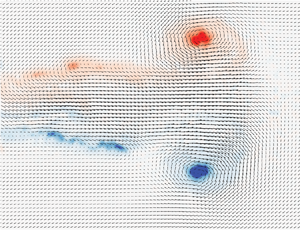
Figure 3(a,d,g) illustrates the vortex-ring formation for  $Re=760$. In figure 3(a,d,g) the vortex ring is more diffuse with an increasing per cent volume fraction,
 $\Phi$. No concentrated vortex ring is formed in dense suspensions, as shown in figure 3(g). For
 ${Re=3040}$, figure 3(b,e) reveals that vorticity fields are similar in both pure water and dilute suspensions. Additionally, a concentrated vortex ring is formed in dense suspensions for the same equivalent Reynolds number, as shown in figure 3(h), but remains more diffuse in comparison to pure water and dilute suspensions. Similar observations are shown in figure 3(c,f,i) for
 $Re=6080$. The change in vorticity distribution in pure water, dilute suspensions, and dense suspensions for the same equivalent Reynolds number reveals that their formation and dynamics is not purely dependent on the equivalent Reynolds number. Figure 3 also shows that the vortex rings in dense suspensions are significantly more diffuse in comparison to pure water and dilute suspensions. Furthermore, figure 3 demonstrates that the influence of the suspended particles on the diffusivity of vortex rings is higher for lower equivalent Reynolds numbers, whereas their influence diminishes significantly for
 $Re>1520$.
The evolution of unconfined vortex rings for  $Re=6080$ in pure water, dilute suspensions and dense suspensions is shown in figures 4(a–c), 4(d–f) and 4(g–i), respectively. Here the vortex rings are in their post-formation stage at time instances
 $T=5$, 6 and 7. It is observed that secondary vortices are formed in pure water once the shear layer from the trailing jet is no longer entrained by the primary vortex, as shown in figure 4(a–c). Similar instabilities in dilute suspensions are demonstrated in figure 4(d–f). For dense suspensions, however, no secondary vortices are formed (figure 4g–i). This reveals that the suspended particles in dense suspensions have a stabilizing effect on vortex rings, and shows that their stability is not purely dependent on the equivalent Reynolds number. This further demonstrates that the dynamics of vortex rings in dense suspensions cannot be accounted for by only considering the effective viscosity of the suspension.
Evolution of vortex rings in (a–c) pure water ( $\Phi =0\,\%$); (d–f) dilute suspensions (
 $\Phi =2\,\%$); and (g–i) dense suspensions (
 $\Phi =20\,\%$) for the unconfined case (
 $D/D_0=4$) for
 $Re=6080$. Vorticity fields at normalized times of
 $T=5$, 6 and 7 are displayed in panels (a,d,g), (b,e,h) and (c,f,i), respectively.

3.1.2. Vortex-core trajectories and diffusion
Upon revealing the influence of the volume fraction and the equivalent Reynolds number on the formation and evolution of unconfined vortex rings, we will now examine the effects of the aforementioned parameters on vortex-core trajectory, vortex-core radius and maximum vorticity. Figure 5(a) illustrates the vortex-core trajectories in pure water, dilute suspensions and dense suspensions for  $Re=3040$, 6080 and 12 160. The vortex-core location is determined by the maximum swirling strength,
 $\lambda _{ci}$. Swirling strength, first proposed by Zhou et al. (Reference Zhou, Adrian, Balachandar and Kendall1999), is the imaginary part of the complex eigenvalues for the velocity gradient tensor and is a measurement of the local swirling rate of the vortex. Note the vortex-ring formation process is very repeatable and the vortex-core trajectory is averaged by ten independent runs. In figure 5(a) the vortex-core trajectory is only dependent on the speed of the piston cylinder, and is independent of the equivalent Reynolds number and volume fraction of the suspension. For instance, the vortex-core trajectory in dense suspensions with
 $Re=6080$ is identical to that in pure water with
 $Re=12\,160$, as both cases implemented the same piston-cylinder speed. This result indicates that the vortex-core trajectory in dense suspensions may be predicted using the results obtained from pure water experiments with similar piston-cylinder speeds. Figure 5(a) also reveals that the trials in pure water and dilute suspensions consistently generate similar vortex-core trajectories. The vortex-core velocity followed the same trend as the vortex-core trajectory. Figure 5(b) displays the vortex-core radius,
 $r/D_0$, for
 $Re=3040$ and 6080. The vortex-core radius is calculated using
 $r=\sqrt {A/{\rm \pi} }$, where
 $A$ is the area of the vortex core, which is defined as the area where
 $\lambda ^2_{ci}>0.25\lambda ^2_{ci,max}$. The threshold value of 25 % of the maximum square of swirling strength is used since the vorticity field of dense suspensions is more disperse in comparison to pure water (see figure 3). This threshold is deemed large enough to prevent the vorticity fluctuations from affecting the measurements of the vortex-core area in dense suspensions. The vortex-core radius and vortex-ring circulation reported in the current study are lower than those found in previous studies, where typical threshold values are approximately 5 % of the maximum swirling strength. Here we use the relative values between pure water, dilute suspensions and dense suspensions, and report on the similarities and differences between each case. In figure 5(b) the vortex-core radius in dense suspensions is significantly larger in comparison to pure water and dilute suspensions, which is a consequence of the diffuse vortex rings in suspensions of higher volume fractions (recall figures 3 and 4). In figure 5(b) the vortex-core radius in pure water and dilute suspensions are similar to one another, with dilute suspensions having a slightly larger vortex-core radius. Figure 5(c) illustrates the maximum vorticity for
 $Re=3040$ and 6080. In figure 5(c) the maximum vorticity decreases with an increasing volume fraction, which corresponds to the observation that an increasing volume fraction results in more diffuse vortex rings, as shown in figures 3 and 4. Finally, in figure 5(b,c) the vortex rings in dense suspensions are observed to be more diffuse in comparison to those in pure water and dilute suspensions. Thus, the modification of their dynamics is clearly not dependent solely on the effective viscosity.
(a) Vortex-core trajectories; (b) vortex-core radius; and (c) maximum vorticity in pure water ( $\Phi =0\,\%$), dilute suspensions (
 $\Phi =2\,\%$) and dense suspensions (
 $\Phi =20\,\%$) for the unconfined case (
 $D/D_0=4$) for
 $1520\leq Re\leq 12\,160$. The location of the vortex core is determined by the maximum swirling strength,
 $\lambda _{ci}$, and the vortex-core area is defined as the area where
 $\lambda ^2_{ci}>0.25\lambda ^2_{ci,max}$.

3.1.3. Vortex-ring circulation and non-dimensional vortex-core radius
Figure 6 illustrates the vortex-ring circulation,  $\Gamma ^*=\Gamma /U_cD_0$, in (a) pure water and dilute suspensions, and (b) dense suspensions for
 $760\leq Re\leq 12\,160$. The vortex-ring circulation is obtained by integrating the vorticity within the vortex-core area,
 $A$, as described in § 3.1.2. Similarly, the vortex-ring circulation values reported are lower than those obtained in previous studies, such as the circulations reported in Weigand & Gharib (Reference Weigand and Gharib1997), Mohseni, Ran & Colonius (Reference Mohseni, Ran and Colonius2001) and Palacios-Morales & Zenit (Reference Palacios-Morales and Zenit2013). In figure 6(a) for
 $Re>3040$, the vortex-ring circulation is nearly constant in pure water and dilute suspensions. However, dense suspensions exhibit a continuous increase in vortex-ring circulation for
 $Re>3040$, which suggests that the jet shear layer is still being entrained by the primary vortex, as shown in figure 6(b). Figure 6(a,b) also shows that dense suspensions have a significantly higher vortex-ring circulation value in comparison to pure water and dilute suspensions at the same equivalent Reynolds number, even though the maximum vorticity is lower (see figure 5c). This is a consequence of dense suspensions having a larger vortex-core radius, where the vortex-ring circulation is integrated over a larger area, thus producing a higher vortex-ring circulation value. Figure 6(c,d) displays the non-dimensional vortex-core radius of the aforementioned fluids. The non-dimensional vortex-core radius,
 $\alpha =r/R$, is defined by Norbury (Reference Norbury1973), where the radii of the vortex core and vortex ring are denoted as
 $r$ and
 $R$, respectively. It is shown in figures 6(a,b) and 6(c,d) that the vortex-ring circulation is directly proportional to the non-dimensional vortex-core radius. A higher value of the non-dimensional vortex-core radius can increase the critical value of the stroke ratio, thus delaying vortex-ring pinch-off, which was shown by Linden & Turner (Reference Linden and Turner2001). In figure 6 the non-dimensional vortex-core radius in dense suspensions is much higher than that in pure water and dilute suspensions at the same equivalent Reynolds number, and vortex-ring pinch-off was delayed. The production of vortex rings with higher non-dimensional vortex-core radius values and the postponement of vortex-ring pinch-off has been observed at very low Reynolds numbers (Palacios-Morales & Zenit Reference Palacios-Morales and Zenit2013; Tinaikar, Advaith & Basu Reference Tinaikar, Advaith and Basu2018), and is also shown in the current experiments for the
 $Re=760$ case. In summary, the vortex rings in dense suspensions are similar to those formed at low Reynolds numbers in pure water. However, the dynamics of vortex rings in dense suspensions are not purely dependent on the equivalent Reynolds number.
(a and b) Vortex-ring circulation. Vortex-ring circulation is calculated by integrating the vorticity with the vortex-core area, which is defined as the area where  $\lambda ^2_{ci}>0.25\lambda ^2_{ci,max}$. (c and d) Non-dimensional vortex-core radius for
 $760\leq Re\leq 12\,160$ for the unconfined case (
 $D/D_0=4$). Pure water (
 $\Phi =0\,\%$) and dilute suspensions (
 $\Phi =2\,\%$) are shown in panels (a and c) and dense suspensions (
 $\Phi =20\,\%$) are displayed in panels (b and d).

3.1.4. Velocity profiles across the vortex core and flow configuration
Figure 7 displays the velocity profiles in the streamwise (section view A) and radial (section view B) directions through the core of the vortex ring in pure water, dilute suspensions and dense suspensions for  $Re=6080$. The boundary of the vortex core in the current study is defined as the threshold where the local shear rate is higher than 10 % of the maximum shear rate of the entire section view (
 $\gamma >0.1\gamma _{max}$). Figure 7(a) illustrates the vorticity contours of the vortex ring in pure water. The boundary of the vortex core is represented by the black squares shown in figures 7(b) and 7(c), and half the distance between the squares represents the vortex-core half-spacings in the streamwise and radial directions, which are denoted by
 $r_1$ and
 $r_2$, respectively. In figures 7(b) and 7(c) the velocity profiles of dilute suspensions are identical to those of pure water in the streamwise and radial directions. The velocity profiles of dense suspensions match with those of pure water and dilute suspensions in the low shear regions, which are also referred to as the jet potential core (
 $0<Y/D_0<0.3$) and the region beyond the volume of the vortex ring (
 $Y/D_0>1$), as shown in figure 7(b). A change in velocity is observed in the high-shear-rate region, which spans
 $0.3<Y/D_0<1$ in figure 7(b). The upper boundary of the vortex ring remains constant in dense suspensions, while the lower jet boundary shear layer is diffuse. The lower boundary of the vortex ring is significantly lower in dense suspensions since the jet boundary is connected to the vortex ring itself, whereas in pure water and dilute suspensions, the jet boundary is disconnected from the vortex ring. Figures 7(a) and 7(c) demonstrate that the suspended particles only influence the flow in high-shear rate regions. The particle Stokes number in the vortex core is estimated as
 $St_p=17.8$, which is calculated by
 $St_p=(1/9){\rho _p}{u_p}{d_p}/\mu _l$ (Joseph et al. Reference Joseph, Zenit, Hunt and Rosenwinkel2001), where
 $u_p$ is the characteristic particle velocity and is assumed to be equal to the jet ejection velocity. In figure 7, the particle Reynolds number in the vortex core of the 20 % suspension can reach a value of
 $Re_p=32$, which can be computed using
 $Re_p={\rho _l}{\tau }{d_p}^2/\mu _l$, where
 $\mu _l$ and
 $\rho _l$ are the fluid viscosity and density, respectively,
 $\tau$ is the shear rate and
 $d_p$ is the particle diameter (Picano et al. Reference Picano, Breugem, Mitra and Brandt2013). When this particle Reynolds number value is large, the particle inertia is known to play an important role. The effective viscosity will thus depend on the particle Reynolds number and will increase significantly when compared with empirical relations (e.g. (2.2)) from the Stokes flow regime (Linares-Guerrero, Hunt & Zenit Reference Linares-Guerrero, Hunt and Zenit2017; Rahmani, Hammouti & Wachs Reference Rahmani, Hammouti and Wachs2018). Based on laboratory measurements in a coaxial-cylinder rheometer, Linares-Guerrero et al. (Reference Linares-Guerrero, Hunt and Zenit2017) observed that the effective viscosity monotonically increased with increasing particle Reynolds number for suspension volume fractions of
 $\Phi \leq 30\,\%$. The measured effective viscosity for
 $\Phi =20\,\%$ and
 $Re_p=30$ was
 $\mu _{sp}\approx 4$. Interestingly, the modification of vortex-ring circulation and non-dimensional vortex-core radius in 20 % suspensions (shown in figure 6) could be compensated by the corrected effective viscosity. For instance, the corrected Reynolds number for the
 $Re=1520$ case in
 $20\,\%$ suspension should be approximately 760. The vortex-ring circulation and non-dimensional vortex-core radius for the
 $Re=1520$ and
 $\Phi =20\,\%$ case (cyan solid lines) are almost the same as for the
 $Re=760$ test case in pure water (blue open diamond lines). The effective viscosity is also dependent on Reynolds number and particle diameter, and the flow conditions in the current study are not the same as in Linares-Guerrero et al. (Reference Linares-Guerrero, Hunt and Zenit2017). The effective viscosity measured by Linares-Guerrero et al. (Reference Linares-Guerrero, Hunt and Zenit2017) may not be directly applied to the current research but their results still indicate that with the increasing of effective viscosity, vortex-rings dynamics in dense suspensions are similar to those formed at low Reynolds numbers in pure water. The particle inertia effects are thus expected to influence vortex-ring dynamics and are therefore likely to be the reason for the differences observed between velocity profiles, as shown in figure 7(b).
Ensemble-averaged velocity profiles through the centre of the vortex ring at normalized time  $T=4$. The section views, A and B, represent the velocity profiles in the streamwise and radial direction, respectively. The vortex half-spacings,
 $r_1$ and
 $r_2$, are determined when the local shear rate is larger than 10 % of the maximum shear rate (
 $\gamma >0.1\gamma _{max}$).

3.1.5. Vortex-ring compression and elongation
The obtained velocity profiles were used to elucidate the topology changes of vortex rings in suspensions. There are three instances when an elliptical vortex ring can be formed: (i) when a vortex ring is generated at low Reynolds numbers of  ${O}(100)$ (Palacios-Morales & Zenit Reference Palacios-Morales and Zenit2013); (ii) a vortex ring is in its post-formation stage (Danaila & Helie Reference Danaila and Helie2008); and (iii) a vortex ring is subjected to a confined domain (Stewart & Vlachos Reference Stewart and Vlachos2012). In figure 3(g–i) vortex rings generated in dense suspensions exhibit an elliptical shape. In order to model the vorticity distribution in the elliptical vortex-core, Kaplanski, Fukumoto & Rudi (Reference Kaplanski, Fukumoto and Rudi2012) introduced two non-dimensional parameters, which are the elongation ratio,
 $\beta$, and the compression ratio,
 $\lambda$. The vorticity of the elliptical vortex core is expressed as
 \begin{equation} \omega^*=\exp{\left(-\frac{{\sigma_1^2}+{{(\eta_1/\beta)}^2+{\theta_1^2}}}{2}\right)}, \end{equation}
where  $\omega ^*$ is normalized by the maximum vorticity, and
 $\sigma _1=Y/{L_1}$,
 ${L_1}=L/{\lambda }$,
 $\eta _1=(X-{X_V})/{L_1}$ and
 $\theta _1=R/{L_1}$. The diffusivity scale of the vortex ring and the diffusivity scale along the radial direction are denoted by
 $L$ and
 $L_1$, respectively. In the current study, we assume that the diffusivity scale of the vortex ring is equal to the vortex-core radius,
 $L=r$, and the radial diffusivity scale is equal to the radial half-spacing of the vortex core,
 $L_1=r_1$. Correspondingly, the compression and elongation ratios are expressed as
 \begin{equation} \lambda=\frac{r}{r_1}, \quad \beta=\frac{r_2}{r_1}. \end{equation}
We assume that the vortex core has an elliptical shape, and the vortex-core radius is calculated using  $r=\sqrt {{{\rm \pi} }r_1r_2}$. From (3.2a,b), the compression and elongation ratios are related by
 $\beta ={\lambda }^2$. With the values of
 $r_1$ and
 $r_2$ obtained using the methods described in figure 7, we can now determine the elongation and compression ratios of the vortex rings in dense suspensions.
Figure 8 reveals the topological characteristics of vortex rings in pure water, dilute suspensions and dense suspensions in terms of their: (a) vortex-core half-spacing in the radial direction,  $r_1$; (b) half-spacing in the streamwise direction,
 $r_2$; and (c) elongation ratio,
 $\beta$, for
 $Re=6080$. Figure 8(a) show that the half-spacing in the radial direction remains relatively constant in pure water and dilute suspensions. Similar observations are deduced from figure 8(b) for the half-spacing in the streamwise direction. However, the half-spacing in the radial and streamwise directions are continuously increasing in dense suspensions. In figure 8(c) the elongation ratio in pure water and dilute suspensions remains relatively constant at a value of
 $\beta \approx 1$, which means that almost no elongation occurs. For dense suspensions, the elongation ratio begins at a value of
 $\beta >1$ and gradually increases, which indicates that the vortex core elongates continuously. The same elongation effect is observed in pure water for
 $Re=760$, which indicates that this feature of the vortex rings in dense suspensions are comparable to those in pure water at low Reynolds numbers.
(a) Vortex-core half-spacing in the radial direction, (b) vortex-core half-spacing in the streamwise direction and (c) elongation ratio.

3.2. Confined vortex rings
3.2.1. Formation and evolution of confined vortex rings
Here we examine the influence of suspended particles on the formation and evolution of confined vortex rings. Vorticity fields of the vortex-ring formation in pure water, dilute suspensions and dense suspensions within a confinement ratio of  $D/D_0=2$ at time instant
 $T=4$ are shown in figures 9(a,b), 9(c,d) and 9(e,f), respectively, for piston-cylinder speeds of 0.08 and
 $0.16\ \textrm {m}\ \textrm {s}^{-1}$. Different piston-cylinder speeds were used rather than equivalent Reynolds numbers since it was revealed in Section 3.1 that the dynamics of vortex rings in dilute and dense suspensions are not purely dependent on the equivalent Reynolds number. Furthermore, the formation of vortex rings is dependent on the speed of the piston cylinder. For instance, the trajectory of the vortex core is only dependent on the speed of the piston cylinder in pure water, dilute suspensions, and dense suspensions, as shown in figure 5(a). It is shown in figures 9(a,b) and 9(c,d) that the vortex rings in pure water and dilute suspensions are nearly identical for both piston-cylinder speeds. It is also shown that the generated vortices in pure water and dilute suspensions exhibit an elliptical shape since they are subjected to a confined flow case. Figure 9(e,f) reveals that the vorticity of dense suspensions in confinement is significantly lower at both piston speeds in comparison to those formed in pure water and dilute suspensions, and the vortex rings in dense suspensions are more diffuse, elongated and compressed.
Formation of primary vortex rings in (a,b) pure water ( $\Phi =0\,\%$); (c,d) dilute suspensions (
 $\Phi =2\,\%$); and (e,f) dense suspensions (
 $\Phi =20\,\%$) for the confined case (
 ${D/D_0=2}$) at normalized time
 $T=4$. Vorticity fields for
 $U_c=0.08$ and
 $0.16\ \textrm {m}\ \textrm {s}^{-1}$ are shown in panels (a,c,e) and (b,d,f), respectively.

Figures 10(a–c), 10(d–f) and 10(g–i) display the evolution of vortex rings with respect to normalized time,  $T$, in pure water, dilute suspensions and dense suspensions, respectively, within a confinement ratio of
 $D/D_0=2$ for a piston-cylinder speed of
 $U_c=0.16\ \textrm {m}\ \textrm {s}^{-1}$. In figure 10(c), the primary vortex breaks down in pure water, while it remains stable in dilute and dense suspensions, as shown in figures 10(f) and 10(i), respectively. Figure 10(g–i) shows that the vortex ring in dense suspensions remains more diffuse in comparison to pure water and dilute suspensions, which was observed in the unconfined case in figure 4. Secondary vortices are inhibited in dense suspensions, as shown in figure 10(i), while such vortices are formed in pure water and dilute suspensions. This demonstrates that the suspended particles in dense suspensions have a significant stabilizing effect on the generated vortex rings, as had been observed for the unconfined case in figure 4.
Evolution of vortex rings in (a–c) pure water ( $\Phi =0\,\%$); (d–f) dilute suspension (
 $\Phi =2\,\%$); and (g–i) dense suspension (
 $\Phi =20\,\%$) for the confined case (
 $D/D_0=2$) for
 $U_c=0.16$ m/s. Vorticity fields at normalized times
 $T=3$, 6 and 8 are displayed in panels (a,d,g), (b,e,h) and (c,f,i), respectively.

3.2.2. Confined vortex-ring circulation and diffusion
Figure 11(a) illustrates the vortex-core trajectories of confined vortex rings for piston-cylinder speeds of 0.08 and  $0.16\ \textrm {m}\ \textrm {s}^{-1}$. The vortex-core trajectories are nearly identical in pure water, dilute suspensions and dense suspensions, regardless of the piston-cylinder speed, as shown in figure 11(a). Similar to the unconfined results shown in figure 5(a), the vortex-core trajectory is independent of the presence of suspended particles. Figure 11(b) shows the vortex-ring circulation for the same piston-cylinder speeds and demonstrates that a higher vortex-ring circulation value corresponds to a lower piston-cylinder speed. Dense suspensions exhibit higher vortex-ring circulation values in comparison to pure water and dilute suspensions for a piston-cylinder speed of
 $U_c=0.16\ \textrm {m}\ \textrm {s}^{-1}$, as shown in figure 11(b), which was also observed in the unconfined case. However, for a piston-cylinder speed of
 $U_c=0.08\ \textrm {m}\ \textrm {s}^{-1}$, the vortex-ring circulation for pure water and dilute suspensions is higher than that of dense suspensions until
 $T=1.5$, at which point the vortex-ring circulation of dense suspensions becomes higher. The vortex-ring circulation in dense suspensions will continue to increase with an increasing stroke ratio,
 $T=L/D_0$, and will eventually surpass the vortex-ring circulation in pure water and dilute suspensions at a specific instant in time. Figure 11(c) displays the non-dimensional vortex-core radius and shows that it is larger in dense suspensions. Furthermore, figure 11(d) reveals that the maximum vorticity is significantly lower in dense suspensions in comparison to that of pure water and dilute suspensions. Both observations made in figures 11(c) and 11(d) were also seen in unconfined cases. Additionally, the maximum vorticity of pure water in the confined case (figure 11d) is much higher than the corresponding value of the unconfined case (figure 5c); however, the maximum vorticity in dense suspensions is similar to that of unconfined cases. This indicates that the dynamics of vortex rings in dense suspensions is insensitive to the confinement ratio. In summary, the confined vortex rings in dense suspensions will remain more diffuse in comparison to those in pure water and dilute suspensions, and will produce a larger vortex-core radius and a lower maximum vorticity, as had been observed in the unconfined cases.
(a) Vortex-core trajectory, (b) normalized vortex-ring circulation, (c) non-dimensional vortex-core radius and (d) maximum vorticity for the confined case.

4. Conclusions
This study presents an experimental investigation of the dynamics of unconfined and confined vortex rings in pure water ( $\Phi =0\,\%$), dilute suspensions (
 $\Phi =2\,\%$) and dense suspensions (
 $\Phi =20\,\%$). Time-resolved PIV measurements were performed using a refractive index matching technique to elucidate the interactions between vortex rings and suspended particles during their formation and evolution. The resultant measurements were used to determine the maximum vorticity, non-dimensional vortex-core radius and vortex-ring circulation. It was observed that the critical Reynolds number to form a concentrated vortex ring is significantly higher in dense suspensions. Specifically, vortex rings in dense suspensions were found to be more diffuse in comparison to those in pure water and dilute suspensions. It was also demonstrated that the vortex rings in dense suspensions remained stable during their evolution in unconfined and confined configurations, whereby the formation of secondary vortices and primary vortex-ring breakdown was impeded. Further results revealed that the vortex-ring circulation and non-dimensional vortex-core radius in dense suspensions remained higher than those in pure water, even with the same equivalent Reynolds number. This demonstrates that the modification of the vortex-ring dynamics in suspensions is not purely a consequence of the equivalent Reynolds number, and thus the effective viscosity of the suspension. Finally, results from the confined case showed that the confinement ratio had little impact on the maximum vorticity, vortex-ring circulation and non-dimensional vortex-core radius in dense suspensions. Thus, the dynamics of vortex rings in dense suspensions is found to be insensitive to confinement. Although the underlying physics causing the stark variance in the vortex-ring dynamics (in suspensions) are still unclear, the current work provides a pathway to explore these interactions between suspended particles and coherent structures. This line of research is still in its infancy and is expected to grow rapidly with the advent of novel experimental tools (such as used here) as well as further increases in computing power.
Acknowledgements
D.E.R. would like to acknowledge the support from the Natural Sciences and Engineering Research Council (NSERC) Discovery Grant.
Declaration of interests
The authors report no conflict of interest.



