





1 Introduction
Laser wakefield acceleration (LWFA)[
Reference Tajima and Dawson
1
] is the most compact technology to produce multi-GeV electron beams[
Reference Miao, Shrock, Feder, Hollinger, Morrison, Nedbailo, Picksley, Song, Wang, Rocca and Milchberg
2
–
Reference Rockafellow, Miao, Shrock, Sloss, Le, Hancock, Zahedpour, Hollinger, Wang, King, Zhang, Šišma, Grittani, Versaci, Gordon, Williams, Reagan, Rocca and Milchberg
5
]. In LWFA, high-power femtosecond laser pulses are focused down to relativistic intensity (normalized amplitude of the laser pulse
${a}_0=\frac{eE_0}{m_\mathrm{e}c{\omega}_0}\approx 2$
 ) on gas targets[
Reference Lorenz, Grittani, Chacon-Golcher, Lazzarini, Limpouch, Nawaz, Nevrkla, Vilanova and Levato
6
–
Reference Miao, Shrock, Rockafellow, Sloss and Milchberg
8
], resulting in the generation of a plasma wave that can withstand accelerating gradients exceeding 100 GV/m[
Reference Matlis, Reed, Bulanov, Chvykov, Kalintchenko, Matsuoka, Rousseau, Yanovsky, Maksimchuk, Kalmykov, Shvets and Downer
9
,
Reference Esarey, Schroeder and Leemans
10
]. This unique feature has motivated the recent LWFA developments in terms of increased repetition rate[
Reference Lazzarini, Grittani, Valenta, Zymak, Antipenkov, Chaulagain, Goncalves, Grenfell, Lamač, Lorenz, Nevrkla, Špaček, Šobr, Szuba, Bakule, Korn and Bulanov
11
] and long-term stability[
Reference Maier, Delbos, Eichner, Hübner, Jalas, Jeppe, Jolly, Kirchen, Leroux, Messner, Schnepp, Trunk, Walker, Werle and Winkler
12
,
Reference Rovige, Huijts, Andriyash, Vernier, Tomkus, Girdauskas, Raciukaitis, Dudutis, Stankevic, Gecys, Ouille, Cheng, Lopez-Martens and Faure
13
]. One of the main technical challenges to be solved in LWFA is that the high-power laser requires high vacuum (
${10}^{-5}$
 mbar) to preserve its quality. Simultaneously, a high volume of gas has to be injected for every laser pulse to generate a new plasma-accelerating cavity.
The injected gas amount can be estimated assuming choked compressible flow through a small orifice into a vacuum chamber. Under this condition, the mass flow rate is determined by the orifice area and the upstream stagnation pressure and temperature[ Reference Anderson 14 ]. The injected mass can then be converted to an equivalent gas volume using the ideal gas relation. For PW-class LWFA systems, the injected volume is typically of the order of hundreds of milliliters per shot, assuming helium gas, a valve inlet pressure of 20–50 bar, an orifice diameter of 1.0–1.5 mm and a valve-opening time of 5–10 ms. In contrast, kHz-repetition-rate LWFA systems typically inject tens of milliliters per second, assuming nitrogen gas, a nozzle orifice diameter approximately equal to 0.1 mm, an inlet pressure of 20–50 bar and continuous gas flow.
Existing working solutions are based on developing closed-volume gas targets[
Reference Maier, Delbos, Eichner, Hübner, Jalas, Jeppe, Jolly, Kirchen, Leroux, Messner, Schnepp, Trunk, Walker, Werle and Winkler
12
], or enclosing the laser–gas interaction volume with a dedicated pumping[
Reference Sayrac, Kolomenskii, Anumula, Boran, Hart, Kaya, Strohaber and Schuessler
15
,
Reference Monzac, Smartsev, Huijts, Rovige, Andriyash, Vernier, Tomkus, Girdauskas, Raciukaitis, Mackevičiūtė, Stankevic, Cavagna, Kaur, Kalouguine, Lopez-Martens and Faure
16
] or differentially pumped cone placed above the gas nozzle[
Reference Bohlen, Wood, Brümmer, Grüner, Lindstrøm, Meisel, Staufer, D’Arcy, Põder and Osterhoff
17
]. The differential pumping system presented in Ref. [Reference Monzac, Smartsev, Huijts, Rovige, Andriyash, Vernier, Tomkus, Girdauskas, Raciukaitis, Mackevičiūtė, Stankevic, Cavagna, Kaur, Kalouguine, Lopez-Martens and Faure16] achieves kHz LWFA operation by means of a dedicated, enclosed multi-stage pumping geometry that allows continuous operation of a high-pressure gas jet while maintaining chamber pressures in the low
${10}^{-4}$
 –
${10}^{-3}$
 mbar range, even for hydrogen backing pressures exceeding 100 bar. This represents an improvement of several orders of magnitude compared to operation without differential pumping and is optimized for ultra-low background pressure along the laser axis.
While the closed-volume solutions enable working at increased repetition rates, they limit the optical and mechanical access to the interaction region[ Reference Biagioni, Bourgeois, Brandi, Cassou, Corner, Crincoli, Cros, Dufrénoy, Douillet, Drobniak, Faure, Gatti, Grittani, Lorenz, Jones, Lucas, Massimo, Mercier, Molodozhentsev, Monzac, Pattathil, Sarri, Sasorov, Shalloo, Steyn, Streeter, Symes, Thaury, Vernier and Wood 18 ], which is required to perform advanced acceleration schemes[ Reference Picksley, Stackhouse, Benedetti, Nakamura, Tsai, Li, Miao, Shrock, Rockafellow, Milchberg, Schroeder, van Tilborg, Esarey, Geddes and Gonsalves 4 , Reference Rockafellow, Miao, Shrock, Sloss, Le, Hancock, Zahedpour, Hollinger, Wang, King, Zhang, Šišma, Grittani, Versaci, Gordon, Williams, Reagan, Rocca and Milchberg 5 , Reference Schmid, Buck, Sears, Mikhailova, Tautz, Herrmann, Geissler, Krausz and Veisz 19 – Reference Špádová, Valenta, Lorenz, Nevrkla, Nejdl, Grittani and Bulanov 22 ], laser–plasma interaction diagnostics[ Reference Matlis, Reed, Bulanov, Chvykov, Kalintchenko, Matsuoka, Rousseau, Yanovsky, Maksimchuk, Kalmykov, Shvets and Downer 9 , Reference Brandi and Gizzi 23 – Reference Galletti, Cianchi, Curcio, Dipace, Ferrario and Pompili 28 ] and laser electron collider experiments[ Reference Cole, Behm, Gerstmayr, Blackburn, Wood, Baird, Duff, Harvey, Ilderton, Joglekar, Krushelnick, Kuschel, Marklund, McKenna, Murphy, Poder, Ridgers, Samarin, Sarri, Symes, Thomas, Warwick, Zepf, Najmudin and Mangles 29 – Reference Russell, Bulanov, Qian, Arran, Blackburn, Bulanov, Grittani, Stuart, Ridgers, Seipt and Alexander 35 ]. In this work we demonstrate a scheme that extracts the gas while preserving full access to the laser–plasma interaction region. This scheme is based on a supersonic gas flow catcher, positioned above the gas jet. A continuously flowing jet and a gas catcher are also used to precisely study nuclear cross-sections of astrophysics relevance and for space research[ Reference Rapagnani, Cutrone, Ranuzzi, De Stefano Fumo, Savino, De Cesare, Buompane, Vecchio, Di Leva, Duarte, Morales-Gallegos, Romoli, Schettino and Gialanella 36 ], with the open access geometry allowing for accurate optical diagnostics[ Reference Brandi, Labate, Rapagnani, Buompane, di Leva, Gialanella and Gizzi 37 ].
Differential pumping approaches based on enclosed (box-like) geometries have demonstrated improvements of one to two orders of magnitude in gas load mitigation under comparable operating conditions[ Reference Monzac, Smartsev, Huijts, Rovige, Andriyash, Vernier, Tomkus, Girdauskas, Raciukaitis, Mackevičiūtė, Stankevic, Cavagna, Kaur, Kalouguine, Lopez-Martens and Faure 16 ]. In contrast to the box-like structure, the skimmer-based approach presented here provides comparable pumping performance while maintaining open geometry.
The differential pumping system in Ref. [Reference Bohlen, Wood, Brümmer, Grüner, Lindstrøm, Meisel, Staufer, D’Arcy, Põder and Osterhoff17] presents the implementation of a differentially pumped cone enabling pulsed gas jet operation with the gas jet opening of 7 ms and repetition rate of 2.5 Hz while keeping the ambient pressure in the interaction chamber at a constant level of
$2\times {10}^{-4}$
 mbar. In this work we are investigating this differential pumping approach and optimizing it towards continuous flow gas jet operation.
2 Design
2.1 Hydrodynamic simulations of gas catching
Let us consider a supersonic nozzle releasing gas into a vacuum chamber, where the resulting gas jet is subsequently captured by a skimmer. In the region comprising the nozzle interior and the near-exit portion of the vacuum chamber (i.e., the simulation domain), the Knudsen number
${Kn=\lambda /L}$
 , where
$\lambda$
 is the mean free path and
$L$
 is a characteristic length scale, remains small (
$Kn<0.01$
 ). In this regime, intermolecular collisions dominate over molecule–wall interactions, the gas remains close to local thermodynamic equilibrium and the continuum hypothesis is valid[
Reference Cercignani
38
,
Reference Bird
39
]. Consequently, the flow can be accurately described by the Navier–Stokes equations with no-slip boundary conditions.
Hydrodynamic simulations were performed to investigate the potential gas-skimming efficiency. The simulations were carried out using commercial ANSYS Fluent release 2023 R1 code. The code solves the compressible Navier–Stokes equations together with the conservation of energy equation, which are commonly used to model compressible nozzle and jet flows[
Reference Anderson
14
,
Reference White
40
]. Turbulence effects are modeled using the shear stress transport (SST)
$k$
 –
$\omega$
 model[
Reference Menter
41
], and the governing equations are discretized using the finite volume method[
Reference Versteeg and Malalasekera
42
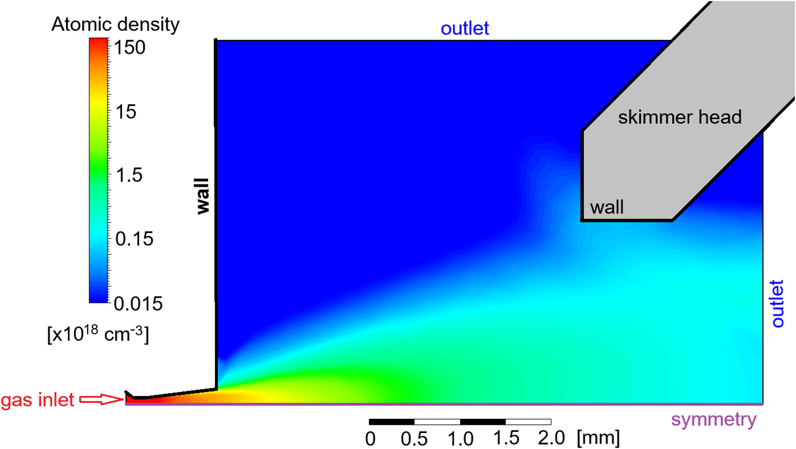
]. The boundary conditions defined in the simulation domain are shown in Figure 1.
Hydrodynamic simulation of the supersonic micro-nozzle with 300 μm exit diameter. The nozzle jet is driven by helium at 30 bar backing pressure. The size of the skimmer orifice is
$d=4$
 mm and the height above the nozzle is
$h=4$
 mm. The figure shows half of the cross-section of the nozzle. The two-dimensional (2D) density profile is plotted in cm
${}^{-3}$
 (number of atoms per cubic centimeter) units. The figure also shows boundary conditions defined in the simulation domain.

Figure 1 Long description
A cross-sectional simulation plot uses a color scale to represent Atomic density in units of times 10 super 18 cm super minus 3. The scale ranges from 0.015 in dark blue to 150 in red.
* Bottom-left: A red arrow points to the gas inlet at the nozzle throat.
* Bottom edge: A purple line labeled symmetry defines the horizontal axis.
* Left edge: A vertical black line labeled wall rises from the nozzle exit.
* Top and Right edges: Labeled outlet in blue text.
* Top-right: A gray geometric shape represents the skimmer head with a horizontal wall boundary.
* Data flow: High-density gas (yellow and green, approximately 1.5 to 15 units) expands from the inlet toward the right. A shock wave structure is visible as a light blue plume (0.15 units) angled upward from the nozzle exit toward the skimmer head.
* Scale bar: Located at the bottom center, measuring 0 to 2.0 mm.
The study focuses on configurations typical for kHz LWFA beamlines such as ALFA[ Reference Lazzarini, Grittani, Valenta, Zymak, Antipenkov, Chaulagain, Goncalves, Grenfell, Lamač, Lorenz, Nevrkla, Špaček, Šobr, Szuba, Bakule, Korn and Bulanov 11 ] and eSYLOS[ Reference Papp, Lécz, Kamperidis and Hafz 43 ]. The considered setup consists of a supersonic micro-nozzle with a 300 μm exit diameter, a 100 μm throat diameter, helium gas at an inlet pressure of 30 bar and a skimmer with a 4 mm orifice diameter positioned 4 mm downstream of the nozzle exit. Under these conditions, the simulated mass flow rate is 111 mL/s (standard milliliters per second) at the nozzle outlet and 101 mL/s at the skimmer inlet. These results indicate that the skimmer captures approximately 91% of the gas exiting the supersonic nozzle (see Figure 1). This demonstrates the high efficiency of gas capture using an inserted skimmer, without the need to enclose the gas target within a box-like structure.
Figure 1 shows that a small fraction of the gas flow is deflected by the front face of the skimmer. This deflection perturbs the gas jet density profile only within approximately 0.5–1 mm downstream of the skimmer. Consequently, the vertical offset of the skimmer relative to the laser-beam axis must be at least 1 mm. This requirement is also consistent with preventing potential ablation of the skimmer tip by the focusing laser pulse. The distance 1 mm from the skimmer to the laser focal spot is chosen to keep the laser intensity below the ablation threshold for fs lasers (
$\approx 1$
 $\ \mathrm{J}/{\mathrm{cm}}^2$
 for aluminum[
Reference Shin and Kim
44
] and AISI 304 stainless steel[
Reference Obergfell, Azarhoushang and Lasagni
45
]) and to avoid material sputtering.
Additional simulations performed for backing pressures in the range of 10–100 bar show that the gas capture efficiency remains approximately constant at approximately equal to 90%. This behavior is consistent with the self-similar structure of supersonic jets under choked-flow conditions, where the overall flow topology is preserved despite changes in absolute density.
2.2 Technical considerations
To put in practice the physical principles demonstrated above, several technical aspects have to be taken into account. Firstly, the gas jet position is being typically adjusted during experiments. For this reason, the skimmer would benefit from motorization. Secondly, the collected gas has to be exhausted effectively and caught in a dedicated line in order to avoid backflow. Thirdly, during the experiment the gas jet (nozzle) can be changed. Therefore, interchangeable skimmer heads with different orifice dimensions should be available.
In laser–plasma experiments, it is crucially important to allow for diagnostics access in the interaction region, such as, for example, a few-cycle synchronized probe beam[ Reference Lorenz, Grittani, Kondo, Kon, Liu, Sagisaka, Ogura, Nakanii, Huang, Bierwage, Namba, Ohiro, Pikuz, Koga, Chen, Kiriyama, Kando, Esirkepov, Bulanov and Pirozhkov 24 , Reference Sävert, Mangles, Schnell, Siminos, Cole, Leier, Reuter, Schwab, Möller, Poder, Jäckel, Paulus, Spielmann, Skupin, Najmudin and Kaluza 46 ]. Moreover, advanced acceleration schemes (e.g., laser guiding experiments[ Reference Miao, Shrock, Feder, Hollinger, Morrison, Nedbailo, Picksley, Song, Wang, Rocca and Milchberg 2 , Reference Picksley, Stackhouse, Benedetti, Nakamura, Tsai, Li, Miao, Shrock, Rockafellow, Milchberg, Schroeder, van Tilborg, Esarey, Geddes and Gonsalves 4 , Reference Rockafellow, Miao, Shrock, Sloss, Le, Hancock, Zahedpour, Hollinger, Wang, King, Zhang, Šišma, Grittani, Versaci, Gordon, Williams, Reagan, Rocca and Milchberg 5 ], two-beam experiments[ Reference Cole, Behm, Gerstmayr, Blackburn, Wood, Baird, Duff, Harvey, Ilderton, Joglekar, Krushelnick, Kuschel, Marklund, McKenna, Murphy, Poder, Ridgers, Samarin, Sarri, Symes, Thomas, Warwick, Zepf, Najmudin and Mangles 29 – Reference Mirzaie, Hojbota, Kim, Pathak, Pak, Kim, Lee, Yoon, Lee, Rhee, Vranic, Amaro, Kim, Sung and Nam 32 , Reference Faure, Rechatin, Norlin, Lifschitz, Glinec and Malka 47 , Reference Wan, Tata, Seemann, Levine, Smartsev, Kroupp and Malka 48 ] or nanoparticle injection[ Reference Aniculaesei, Ha, Yoffe, Labun, Milton, McCary, Spinks, Quevedo, Labun, Sain, Hannasch, Zgadzaj, Pagano, Franco-Altamirano, Ringuette, Gaul, Luedtke, Tiwari, Ersfeld, Brunetti, Ruhl, Ditmire, Bruce, Donovan, Downer, Jaroszynski and Hegelich 3 , Reference Špádová, Valenta, Lorenz, Nevrkla, Nejdl, Grittani and Bulanov 22 ]) also require free 360-degree access to the interaction volume.
Finally, operating a continuous flow gas target system suppresses the effects of omnipresent broad band high-frequency bursts of electromagnetic (EM) radiation emitted during the interaction (electromagnetic pulse (EMP)) on the pulsed valve driving electronics. Also, mechanical instabilities initiated by high-repetition-rate pulsed gas jets are eliminated.
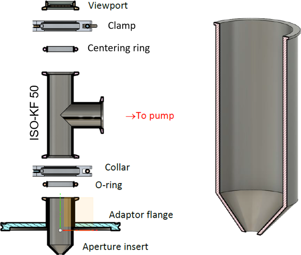
Figure 2 shows the final design of the gas skimmer assembly used in the following experiments. The assembly includes a stainless steel skimmer head with the tube diameter of 50 mm. The skimmer head is connected through standard ISO-KF 50 flanges and a T-tube to the roughing pumping system. The assembly includes a viewport on top to allow for top-view diagnostics that are crucial for laser–plasma experiment alignment.
Scheme of the assembly of the skimmer (left) and the skimmer head design cross-section (right).

Figure 2 Long description
The left panel shows an exploded vertical assembly of vacuum components. From top to bottom, the components are labeled as Viewport, Clamp, Centering ring, and a T-shaped pipe labeled I S O dash K F 50. A red arrow points right from the side port of the T-pipe with the text ‘To pump’. Below the T-pipe are a Collar, an O-ring, an Adaptor flange, and an Aperture insert at the base. The right panel shows a detailed cross-section of the skimmer head. It is a cylindrical vessel with a wide top opening and thick walls. The bottom of the vessel tapers into a conical shape, terminating in a small central aperture. The interior of the tapered section is smooth, while the outer walls show a hatched pattern indicating the material thickness.
3 Gas load testing in kHz beamlines
3.1 ALFA beamline
The skimmer was tested in two different laser–plasma experimental vacuum chambers. In the ALFA beamline at ELI Beamlines facility the skimmer was tested on a rectangular vacuum chamber with dimensions of
$1.2\times 1.5\times 0.65=1.2$
 m3. The chamber was pumped by two turbo-molecular pumps, and the skimmer was connected to the roughing central vacuum line in the L1 laser hall with 40 mm diameter, 2 m long vacuum flexible tubing.
The ALFA chamber is designed for high-vacuum operation. All vacuum components and pumps attached to the chamber are compatible with a vacuum range of
${10}^{-6}$
 mbar as the final pressure. The pumping sequence includes independent rough pumping of the chamber and continuous evacuation via turbo-molecular pumps.
For cleanliness reasons[
Reference Borneis, Laštovička, Sokol, Jeong, Condamine, Renner, Tikhonchuk, Bohlin, Fajstavr, Hernandez, Jourdain, Kumar, Modřanský, Pokorný, Wolf, Zhai, Korn and Weber
49
], the gate valve between the L1-ALLEGRA laser and ALFA is opened only once the
$2\times {10}^{-5}$
 mbar vacuum level is reached. The maximum level during operation is
$3\times {10}^{-2}$
 mbar to prevent the turbo-molecular pumps from heating.
The two turbo-molecular pumps mentioned above are used as the main pumps for the high vacuum. They are magnetically levitated pumps made by Pfeiffer Vacuum, type HiPace 700M, with external controllers. Each of them has a pumping speed of 685 L/s (N
${}_2$
 ). The forevacuum side of each pump is equipped with a forevacuum valve for isolation from the central vacuum system.
The ALFA chamber is located in the L1 hall in ELI Beamlines with its own central vacuum system. The system has two main pipelines. The roughing line is used for evacuating vacuum vessels to a pressure region of
${10}^{-2}$
 mbar. The backing line is used to evacuate the forevacuum side of the turbo-molecular pumps and to support particular vacuum systems.
The roughing line consists of a dry screw vacuum pump and pipeline. The primary pump is made by Edwards. It is a GXS450/2600F HV LD SE SK, with a pumping speed of 600 L/s and an ultimate pressure of
$5\times {10}^{-4}$
 mbar. The pump is located in a technical room next to the L1 laser hall. The roughing pipeline mostly consists of DN160 tubes and is approximately 52 m long.
The backing line consists of a dry screw vacuum pump and pipeline. The primary pump is made by Edwards. It is a GXS160/1750F HV MD SE SK, with a pumping speed of 320 L/s and an ultimate pressure of
$7\times {10}^{-4}$
 mbar. This pump has an optional additional purge gas line for pumping specific gases. The pump is located next to the L1 laser hall. The backing pipeline is mostly 100 mm in diameter and 45 m long.
Both lines of the central vacuum system have primary pumps equipped with boosters. Thanks to that, the system provides relatively high pumping speed and low ultimate pressure. The ultimate pressure at the pipeline endpoints is in the
${10}^{-2}$
 mbar range, which is sufficient for most applications.
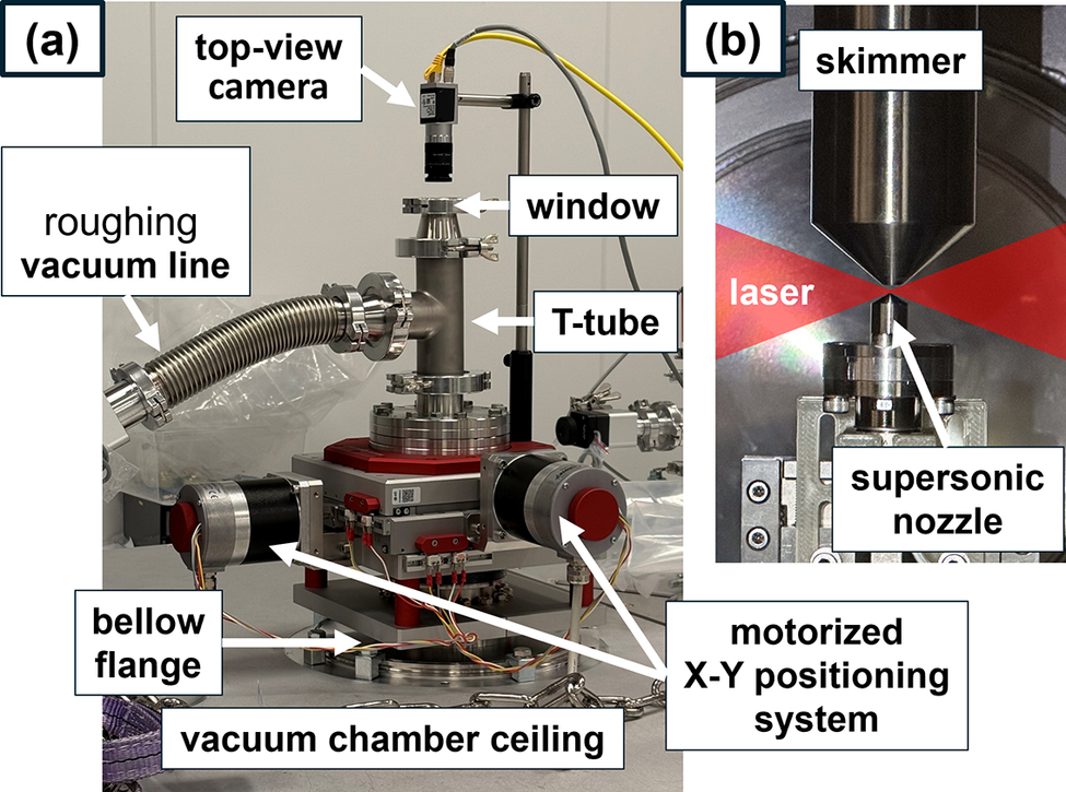
Figure 3 shows the skimmer motorization system and connection to dedicated exhaust line (Figure 3(a)) and the skimmer head positioning on top of the nozzle (Figure 3(b)).
Gas jet catcher design. (a) Full assembly installed on top of the ALFA beamline vacuum chamber. The assembly consists of the skimmer (inside), two-axis positioning stage, feed-through, top window for diagnostics, open/close valve and connection to the roughing line. (b) Image of the supersonic nozzle and the skimmer inside the vacuum chamber during the test in the CNR-INO laboratory. The focused laser beam is marked in red.

Figure 3 Long description
A two-panel figure showing experimental hardware.
Panel a is a photo of the full assembly. At the top, a top-view camera is mounted on a vertical post, looking down through a circular window into a vertical T-tube. To the left, a flexible metal hose labeled roughing vacuum line connects to the side of the T-tube. The T-tube is mounted on a red and silver motorized X-Y positioning system with two cylindrical motors extending horizontally. Below this is a bellow flange which connects the entire assembly to the vacuum chamber ceiling.
Panel b is a close-up photo of the internal components. At the top is a conical metal skimmer with its point facing downward. Below it is a small supersonic nozzle with its tip facing upward. A red shaded area represents a focused laser beam passing horizontally through the narrow gap between the skimmer tip and the supersonic nozzle.
The tests were carried out using nitrogen and helium as working gases. The following plots present the experimentally measured performance of the supersonic gas jet catcher system for differential pumping in laser–plasma interaction experiments as a function of three parameters: the vertical distance between the skimmer and the nozzle exit, the lateral alignment of the skimmer relative to the nozzle axis and the nozzle backing pressure. The vertical axis in these plots represents the performance metrics. When the system, in the dedicated experimental configuration, is able to reach a steady-state flow regime (continuous operation for more than 5 minutes) without exceeding the ambient pressure safety threshold, the ambient pressure in the chamber is recorded and plotted as the performance parameter. Conversely, when the gas load is a lot higher than the ambient pressure and the safety limit is surpassed, the plotted performance parameter value corresponds to the time required to reach this limit, that is, the maximum permissible valve-opening duration.
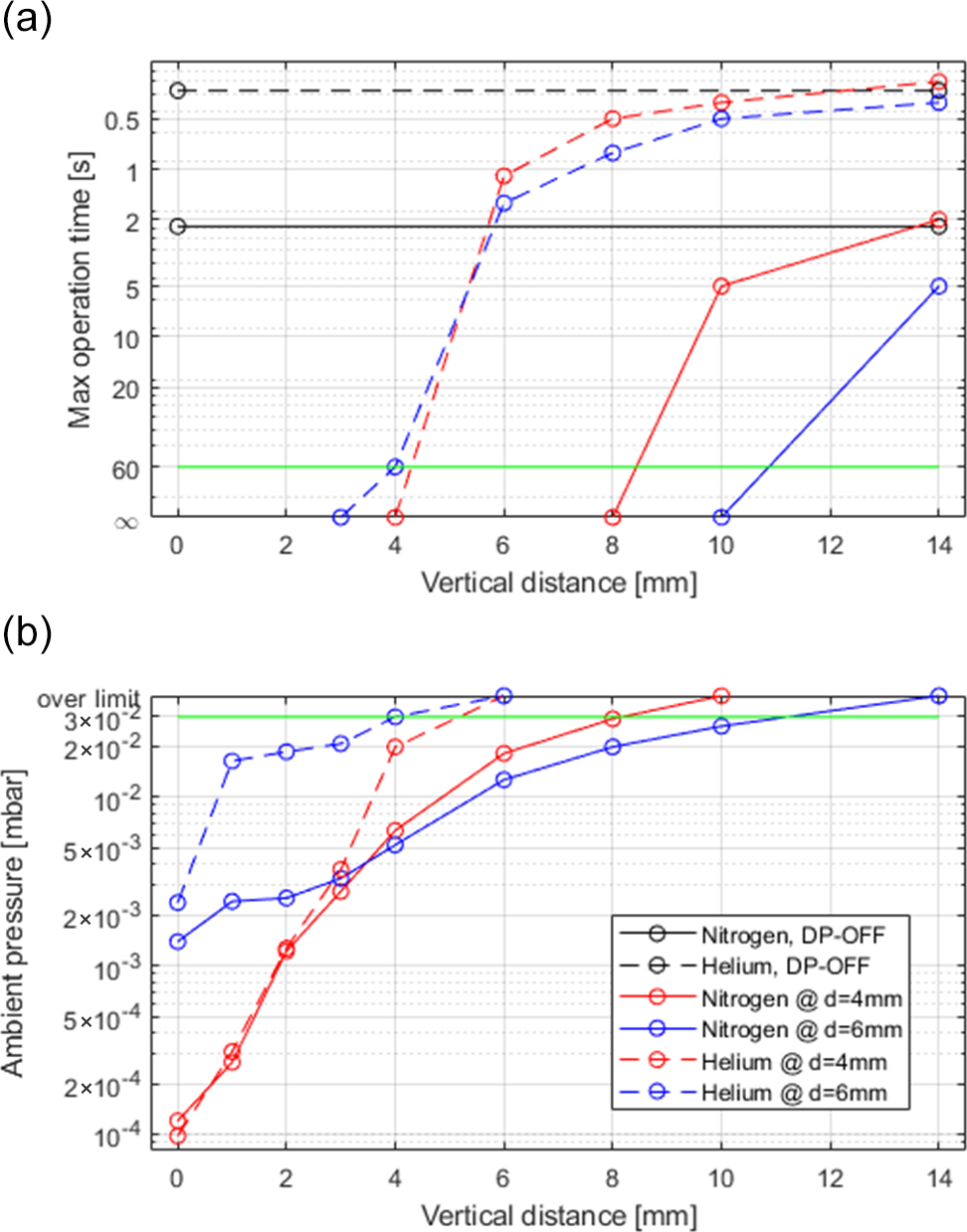
Figure 4 shows the measured pressures for different vertical positions of the skimmer relative to the top of the nozzle. This parameter is critical because experiments require a balance between gas-catching efficiency and unobstructed access to the interaction region. In typical ALFA operation, the laser is focused 100–300 μm above the nozzle, which sets a minimum safe skimmer distance of approximately 1 mm. The measurements were carried out using two skimmer orifice diameters and are compared to results obtained without differential pumping.
Skimmer vertical position scan at 6.2 bar inlet pressure for helium (dashed lines) and nitrogen (solid lines). The system performance is measured in two separate modes: (a) maximum operation time until reaching the vacuum safety limit and (b) ambient pressure in the vacuum chamber during continuous flow operation if the system allows it. The values for switching off differential pumping are marked with black lines. The safety vacuum limit of
$3\times {10}^{-2}$
 mbar is marked with a green solid line.

Figure 4 Long description
The image consists of two vertically stacked line graphs, labeled a and b. Both share an x-axis representing Vertical distance in millimeters from 0 to 14.
Panel a: The y-axis represents Max operation time in seconds on a logarithmic scale, ranging from infinity at the bottom to 0.5 at the top.
- A green solid horizontal line at 60 seconds marks the safety vacuum limit.
- Two horizontal black lines represent D P-O F F modes: helium (dashed) near 0.5 seconds and nitrogen (solid) near 2 seconds.
- Helium data (dashed lines with circles): At d equals 4 mm, the time is 60 seconds, then sharply decreases to 1 second at d equals 6 mm, plateauing near 0.5 seconds.
- Nitrogen data (solid lines with circles): At d equals 8 mm, the time is infinity, then drops to 5 seconds at d equals 10 mm and 2 seconds at d equals 14 mm.
Panel b: The y-axis represents Ambient pressure in mbar on a logarithmic scale from 10 super minus 4 to 3 times 10 super minus 2, with an ‘over limit’ marker at the top.
- A green solid horizontal line marks the safety limit at 3 times 10 super minus 2 mbar.
- Helium at d equals 4 mm (red dashed) starts at 10 super minus 4 at x equals 0 and rises steeply to the safety limit by x equals 6.
- Nitrogen at d equals 4 mm (red solid) follows a similar steep upward trajectory.
- Helium at d equals 6 mm (blue dashed) starts higher at 2 times 10 super minus 3 and reaches the over limit state by x equals 6.
- Nitrogen at d equals 6 mm (blue solid) shows a more gradual logarithmic increase, staying below the safety limit until x equals 14.
The data indicate that the differential pumping system operates reliably for skimmer–nozzle separations between 1 and 10 mm, with system performance showing a strong dependence on this distance.
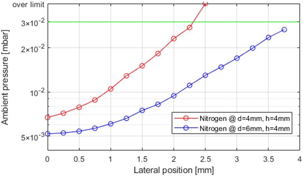
Figure 5 shows the effect of lateral misalignment of the skimmer for two orifice diameters. The measurements were performed at a fixed height of 4 mm above the nozzle, a configuration that is experimentally relevant and predicted by hydrodynamic simulations to provide efficient pumping. Orifice diameters of
$d=4$
 mm and
$d=6$
 mm were chosen based on the gas jet dimensions shown in Figure 1.
Skimmer lateral position scan at 6.2 bar backing pressure for nitrogen. The skimmer distance from the nozzle is fixed at 4 mm. The plot shows ambient pressure in the vacuum chamber for two skimmers with different orifice diameters (the red line refers to the skimmer with
$d=4$
 mm, while the blue line refers to the skimmer with
$d=6$
 mm). The safety vacuum limit of
$3\times {10}^{-2}$
 mbar is marked with a green solid line.

Figure 5 Long description
The x-axis represents Lateral position in millimeters, ranging from 0 to 4. The y-axis represents ambient pressure in mbar on a logarithmic scale, ranging from 5 times 10 super minus 3 to over limit.
* A horizontal green solid line at 3 times 10 super minus 2 mbar marks the safety vacuum limit.
* The red line with open circle markers represents Nitrogen at d equals 4 mm and h equals 4 mm. It starts at approximately 7 times 10 super minus 3 mbar at position 0 and follows an exponential upward curve, crossing the green safety limit at a lateral position of approximately 2.3 mm.
* The blue line with open circle markers represents Nitrogen at d equals 6 mm and h equals 4 mm. It starts lower, at approximately 5.5 times 10 super minus 3 mbar at position 0, and follows a similar but shallower exponential upward trend, reaching approximately 2.8 times 10 super minus 2 mbar at a lateral position of 3.75 mm, remaining just below the safety limit.
This study was conducted to assess whether motorization of the skimmer is necessary. The results show that even if the skimmer remains fixed near the nozzle axis, sufficient tolerance exists for target-position adjustments during laser–plasma optimization. The gas target position can be varied by approximately
$\pm 200\ \unicode{x3bc} \mathrm{m}$
 without significantly affecting the performance of the differential pumping system.
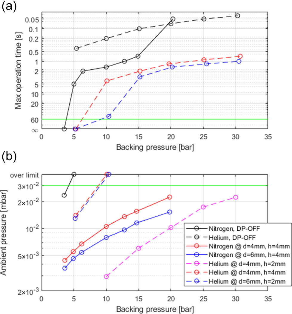
Figure 6 presents the pumping system efficiency of the differential pumping system as a function of the backing pressure supplied to the nozzle. Pumping system efficiency is defined here as the ability to sustain higher gas throughput while keeping the chamber pressure below the safety limit. The improvement results from direct gas interception by the skimmer (
$\approx$
 90% capture from simulations) and reduced gas load on the turbo-molecular pumps. With differential pumping, higher backing pressures can be operated at significantly lower chamber pressure, corresponding to an improvement exceeding two orders of magnitude.
Nozzle inlet pressure scans for helium (dashed lines) and nitrogen (solid lines). The system performance is measured in two separate modes: (a) maximum operation time until reaching the vacuum safety limit and (b) ambient pressure in the vacuum chamber during continuous flow operation if the system allows it. Five different cases with different skimmer orifices (4 or 6 mm) and skimmer heights above the nozzle (2 or 4 mm) were studied. For reference the values for switching off differential pumping are presented as black lines. The safety vacuum limit of
$3\times {10}^{-2}$
 mbar is marked with a green solid line.

Figure 6 Long description
Two line graphs labeled a and b share a horizontal x-axis representing Backing pressure in bar, ranging from 0 to 35.
Panel a: The y-axis represents Max operation time in seconds on a logarithmic scale, ranging from infinity at the bottom to 0.05 at the top. A horizontal green line marks the safety limit at 60 seconds. Data for Nitrogen (solid lines) and Helium (dashed lines) show that as backing pressure increases, maximum operation time decreases. The black lines (D P-O F F) drop most sharply, reaching the safety limit at approximately 4 bar for Nitrogen and 5 bar for Helium. Red and blue lines represent different skimmer setups, showing longer operation times than the D P-O F F reference.
Panel b: The y-axis represents Ambient pressure in mbar on a logarithmic scale, ranging from 2 times 10 super minus 3 to over limit. A horizontal green line marks the safety vacuum limit at 3 times 10 super minus 2 mbar. The graph plots several series:
- Nitrogen, D P-O F F: Solid black line rising steeply toward the limit.
- Helium, D P-O F F: Dashed black line rising steeply toward the limit.
- Nitrogen at d equals 4 mm, h equals 4 mm: Solid red line with a moderate upward slope.
- Nitrogen at d equals 6 mm, h equals 4 mm: Solid blue line with a moderate upward slope, positioned below the red line.
- Helium at d equals 4 mm, h equals 2 mm: Dashed magenta line with a gradual upward slope.
- Helium at d equals 4 mm, h equals 4 mm: Dashed red line rising steeply.
- Helium at d equals 6 mm, h equals 2 mm: Dashed blue line rising steeply.
In both panels, Nitrogen generally reaches pressure limits or operation time thresholds at lower backing pressures compared to Helium for equivalent skimmer geometries.
The reported improvement of more than two orders of magnitude refers to the comparison between operation without differential pumping (ambient pressure
$\approx 3\times {10}^{-2}$
 mbar at
$\approx$
 4 bar nitrogen) and operation with the skimmer installed (
$\approx 3\times {10}^{-4}$
 mbar at 6.2 bar nitrogen).
In all of the above-mentioned measurements, where the system was able to reach steady-state operation, there were no ambient pressure fluctuations evident from the pressure gauge readings. Therefore, we can state that the ambient pressure fluctuations during the differential pumping line operation were lower than 1% of the plotted values.
3.2 Intense laser irradiation laboratory test
The second campaign was designed to validate the robustness and scalability of the differential pumping concept under simplified and cost-effective pumping conditions. This allows assessing the applicability of the system beyond large-scale facilities, demonstrating its suitability for smaller laboratory environments with limited vacuum infrastructure. Electron acceleration data were not acquired during this test. In the Intense Laser Irradiation Laboratory (ILIL) at CNR-INO, the skimmer has been tested on a round vacuum chamber with a diameter of
$1$
 m and a height of
$0.6$
 m. The chamber is pumped by a roughing scroll pump (Agilent TriScroll 600, 420 L/min) and turbo-molecular pump (Alcatel 5400, 400 L/s nitrogen). An additional vacuum pump unit has been used to evacuate a 7-m-long and 57 mm diameter laser propagation tube connected to the interaction vacuum chamber. The vacuum pump unit faced the tube directly and consisted of a diaphragm backing pump (Varian 949-9412, 63 L/min) and a turbo-molecular pump (Varian Turbo-V 300 HT, 250 L/s). Finally, the skimmer was connected to an additional scroll pump (Varian TriScroll 600, 500 L/min) with a 50 mm diameter, 3 m long vacuum flexible tubing without the T-tube and the top viewport.
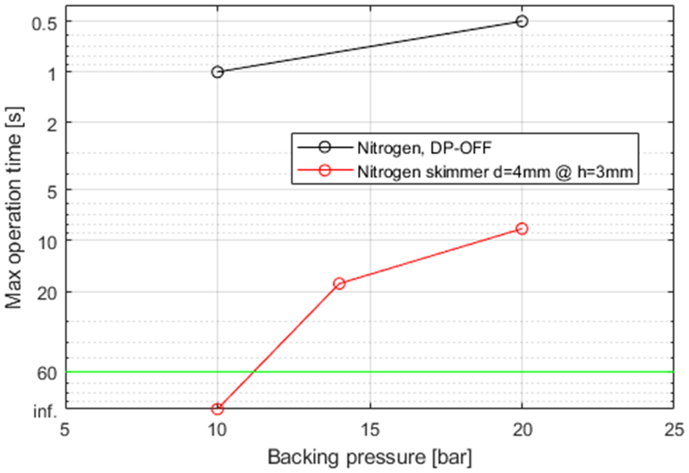
Figure 7 shows the efficiency of the differential pumping setup with a simple scroll pump connected to the skimmer for different backing pressures of the gas flowing through the nozzle. In this case, the improvement corresponds to an increase in the maximum allowable operation time before reaching the safety pressure limit (e.g., from
$\approx$
 0.5 s to
$\approx$
 8 s at 20 bar), that is, about one order of magnitude. This enables operating the gas jet in continuous flow in nitrogen for backing pressures up to 10 bar and in burst mode over several seconds for backing pressures around 20 bar.
Nozzle inlet pressure scan for nitrogen (red line) done with the cost-effective setup built in the ILIL. The system performance is measured in maximum operation time until reaching the vacuum safety limit (
$5\times {10}^{-2}$
 mbar). The skimmer with an orifice diameter of 4 mm was used and the skimmer height above the nozzle was fixed to 3 mm. For reference the values for switching off differential pumping are presented as a black line.

Figure 7 Long description
The x-axis represents Backing pressure in bar, ranging from 5 to 25. The y-axis represents Max operation time in seconds on a logarithmic scale that decreases as it moves upward, with values labeled from infinity at the bottom to 0.5 at the top. A horizontal green line is fixed at the 60 second mark.
Two data series are plotted:
* Nitrogen, D P-O F F: A black line with open circles showing a slight upward trend. It starts at 10 bar with a time of 1 second and ends at 20 bar with a time of 0.5 seconds.
* Nitrogen skimmer d=4mm at h=3mm: A red line with open circles showing a steeper upward trend. It starts at 10 bar at the infinity mark, rises to approximately 18 seconds at 14 bar, and reaches approximately 8 seconds at 20 bar.
The red line remains below the black line across all measured pressures, indicating longer operation times for the skimmer setup compared to the D P-O F F reference.
4 System demonstration in a 1 kHz laser wakefield acceleration beamline
The system described above has been fully tested and integrated in the ALFA beamline to enhance the offer for user experiments, allowing the possibility of producing continuously relativistic electrons at 1 kHz repetition rate. This is of fundamental importance for all experiments requiring electron beams with high current and high dose rate delivery. Therefore, operation is at the maximum available repetition rate of the L1-ALFA system, as described in the work by Lazzarini et al. [ Reference Lazzarini, Grittani, Valenta, Zymak, Antipenkov, Chaulagain, Goncalves, Grenfell, Lamač, Lorenz, Nevrkla, Špaček, Šobr, Szuba, Bakule, Korn and Bulanov 11 ].
To demonstrate this, we have tested the effect of the differential pumping solution on the electron beams, by turning it on and off after having achieved a stable acceleration configuration. We have used the L1 laser at the available energy of 45 mJ and pulse duration of 15 fs full width at half maximum (FWHM). The laser was focused by an f/5 off-axis parabola (OAP) to a waist radius of
${w}_0=6\pm 0.5$
 μm (Rayleigh length
${z}_{\mathrm{R}}\approxeq 100$
 μm) into a supersonic in-house designed gas jet with an output diameter of 300 μm and a throat diameter 100 μm. As target gas we have chosen nitrogen, at a backing pressure of 5 bar, producing a plasma density of
$5\times {10}^{19}$
 cm
${}^{-3}$
 . The plasma density is determined by the gas jet parameters and backing pressure, and has been previously characterized for the same nozzle geometry[
Reference Lorenz, Grittani, Chacon-Golcher, Lazzarini, Limpouch, Nawaz, Nevrkla, Vilanova and Levato
6
,
Reference Lazzarini, Grittani, Valenta, Zymak, Antipenkov, Chaulagain, Goncalves, Grenfell, Lamač, Lorenz, Nevrkla, Špaček, Šobr, Szuba, Bakule, Korn and Bulanov
11
]. The flowing gas was collected by the skimmer head with an orifice diameter of 4 mm positioned 3 mm above the nozzle exit. The skimmer was laterally cantered with the nozzle. The alignment was made with the top-view and side-view cameras. The presence of the skimmer, positioned several millimeters above the interaction region, does not significantly perturb the plasma density profile at the laser focus, as also supported by the hydrodynamic simulations presented in Section 2.1.
This test was performed during a preparation phase for a specific user experiment requiring stable high-energy electron beams. Therefore, we have optimized the laser focusing inside the plasma profile, aiming to maximize the beam charge at high energy (i.e., >
$10$
 MeV) without prioritizing low-energy spread, achieving an average current of 120 pA.
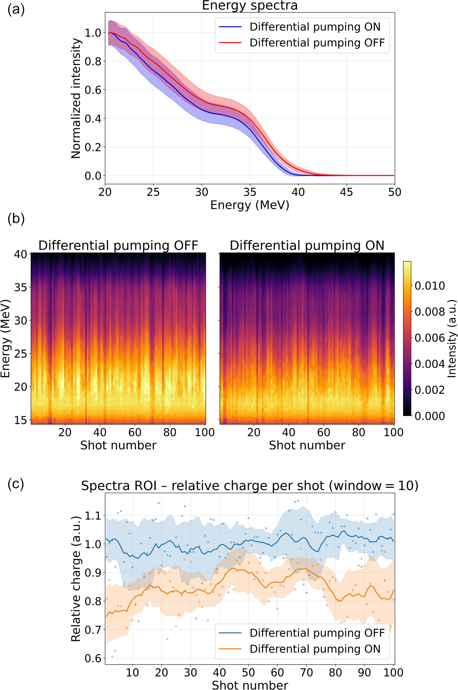
In Figure 8(a), we show the one-dimensional (1D) electron spectra, averaged over 100 images each, saved with an acquisition time of 200 ms (i.e., 20,000 consecutive electron beams) for the two cases of differential pumping on and off. In Figure 8(b) we show 100 consecutive electron spectra and in Figure 8(c) we show the charge stability for both configurations. Each electron shot is acquired with a 200 ms exposure time, so it is integrated over 200 laser shots.
Experimental results obtained in the ALFA beamline with and without operation of the differential pumping setup: (a) the 1D electron spectra for the two cases of differential pumping on and off; (b) 100 consecutive electron spectra; (c) the charge stability of the electron beams.

Figure 8 Long description
Panel a is a line graph titled Energy spectra. The x-axis is Energy in M e V from 20 to 50. The y-axis is Normalized intensity from 0.0 to 1.0. Two curves with shaded error regions are shown. The blue line (Differential pumping O N) and red line (Differential pumping O F F) both show a downward trend from 20 to 40 M e V, with a slight plateau around 32 M e V before dropping to zero at 40 M e V. The red line maintains slightly higher intensity than the blue line throughout.
Panel b contains two side-by-side heatmaps titled Differential pumping O F F and Differential pumping O N. The x-axis is Shot number from 0 to 100 and the y-axis is Energy in M e V from 15 to 40. A color bar on the right indicates Intensity in a. u. from 0.000 (black) to 0.010 (yellow). Both heatmaps show vertical streaks of high intensity (yellow/orange) concentrated between 15 and 30 M e V across all 100 shots.
Panel c is a scatter and line plot titled Spectra R O I - relative charge per shot (window = 10). The x-axis is Shot number from 0 to 100 and the y-axis is Relative charge in a. u. from 0.6 to 1.1. The blue data (Differential pumping O F F) fluctuates around a mean of 1.0. The orange data (Differential pumping O N) fluctuates around a lower mean of approximately 0.85. Both datasets include individual data points and a smoothed moving average line with shaded variance regions.
The electron beam data were retrieved with the ALFA electron beam spectrometer, consisting of a motorized collimator slit, a motorized permanent magnetic dipole and a LANEX scintillator screen captured by a global shutter complementary metal–oxide–semiconductor (CMOS) camera, as described in Refs. [Reference Lazzarini, Grittani, Valenta, Zymak, Antipenkov, Chaulagain, Goncalves, Grenfell, Lamač, Lorenz, Nevrkla, Špaček, Šobr, Szuba, Bakule, Korn and Bulanov11,Reference Zymak, Favetta, Grittani, Lazzarini, Tassielli, Grenfell, Goncalves, Lorenz, Sluková, Vitha, Versaci, Chacon-Golcher, Nevrkla, Šišma, Antipenkov, Šobr, Szuba, Staufer, Grüner, Lapadula, Ranieri, Piombino, Hafz, Kamperidis, Papp, Mondal, Bakule and Bulanov50]. To be sure to have the same laser–plasma conditions and the same test electron beam, these data sets were saved one after the other within a couple of minutes (the minimum time to enter the target area and open the gas collection path valve), while leaving the laser running in the target chamber.
It is clear that when we turned on the differential pumping system, the electron beam spectrum does not change, within the error of the measurement here indicated by one standard deviation over the same set of data. The average charge is slightly different, but still in the typical fluctuation range of the ALFA beamline. This does not represent a problem for sample irradiation experiments as the total dose can be still achieved by tuning accordingly the irradiation time. It demonstrates the possibility to activate the on-demand differential pumping solution presented in this work whenever it is necessary for the working target pressures, without affecting the electron beam quality.
5 Conclusion
We have developed and experimentally validated a supersonic gas jet catcher for differential pumping in laser–plasma interaction experiments. The system enables efficient extraction of continuously flowing gas jets while preserving full optical and mechanical access to the interaction region.
Simulations indicate a gas capture efficiency of approximately 90%, which is confirmed experimentally by a significant reduction of the gas load on the vacuum system. In the ALFA beamline, this allows stable continuous operation at higher backing pressures while maintaining chamber pressures in the
${10}^{-4}$
 mbar range, corresponding to an improvement exceeding two orders of magnitude compared to operation without differential pumping. Tests in a simplified setup further demonstrate the robustness of the approach under reduced pumping conditions.
The system does not measurably affect the accelerated electron beam properties, confirming its compatibility with LWFA operation. These results establish the gas jet catcher as an effective and minimally invasive solution for high-repetition-rate laser–plasma experiments requiring both high gas throughput and open interaction geometry.
Acknowledgements
This work was supported by the National Science Foundation and Czech Science Foundation under NSF-GACR collaborative Grant No. 2206059 from the Czech Science Foundation Grant No. 22-42963L, and received funding through the projects EU Horizon 2020 Research and Innovation Program EuPRAXIA Preparatory Phase, under Grant Agreement No. 101079773 and EU Horizon IFAST, under Grant Agreement No. 101004730. The research has been co-funded by the European Union - NextGeneration EU through the Italian PNRR MUR projects ‘Integrated infrastructure initiative in Photonic and Quantum Sciences’ - I-PHOQS (IR0000016, ID D2B8D520, CUP B53C22001750006), ‘EuPRAXIA Advanced Photon Sources’ – EuAPS (IR0000030, CUP I93C21000160006) and ‘Tuscany Health Ecosystem (THE)-Spoke 1: Advanced Radiotherapies and Diagnostics in Oncology’ (ECS00000017, D.D. MUR No. 1055 23 May 2022).








 Open access

