I. INTRODUCTION
Solid-state thermoelectric (TE) devices are utilized in both cooling and electrical power generation applications and have several advantages over other methods, including: absence of moving parts, low maintenance, long life, and high reliability.Reference Nolas, Sharp and Goldsmid1–Reference Bell3 A device typically comprised two ceramics that are metalized with copper,Reference Brostow, Datashvili, McCarty and White4 an array of TE elements, and a solder that joins the device together.Reference Bierschenk, Priya and Inman5–Reference Rowe7 TE generator (TEG) applications have a wide range of temperature requirements with sensor energy harvesting TEGs operating around 85 °C,8 standard consumer product TEGs up to about 250 °C,9 automotive waste heat recovery TEGs up to about 500 °C,Reference Sales, Mandrus and Williams10 and radioisotope TEGs (RTGs) operating up to about 1025 °C.Reference Fleurial11 Different TE materials are required to optimize the peak TE performance at the different temperatures. For example, bismuth telluride (Bi2Te3) alloys are satisfactory up to ∼250 °C, various lead telluride alloys and skutterudites satisfactory in the temperature range of 500–700 °C, and silicon germanium (SiGe) and other skutterudites up to ∼1025 °C.Reference Tritt, Böttner and Chen12, Reference Yu, Zhang, Wang, Wang, Wang, Wang, Wang, Snyder, Chen and Ren13 Much effort has gone into improving the bulk TE material performance for materials in each of these temperature ranges including novel engineering of nanoscale grains and interfaces.Reference Medlin and Snyder14 Our work, however, focuses on protection of the TE material at a more macroscale, i.e., at the device assembly level.
At TEG operating temperatures, the different TE materials need protection to prevent sublimation and reaction with oxidative and corrosive environments depending on the specific application. TEGs experience preferential sublimation of the thermoelectric material. For example, in (Bi2Te3) alloys, tellurium (Te) sublimes before either bismuth (Bi) or lead (Pb) and deposits in empty spaces as a film or as Te oxide needles; similarly antimony (Sb) preferentially sublimes in the skutterudite antimonides, germanium (Ge) in SiGe, and Te in lead telluride (PbTe).Reference El-Genk, Saber, Caillat and Sakamoto15, Reference Sakamoto, Caillat, Fleurial and Snyder16 We note that n type Bi2Te3materials typically contain selenium (Se).
Previous studies have evaluated silicon dioxide (SiO2), metals and silica aerogelReference Jones and Sakamoto17 as potential protective coatings on the TE elements. Ba0.3In0.2Ni0.05Co3.95Sb12/SiO2 nanocomposite material with a nano-SiO2 coating showed improved thermal stability after cycling to 450 °C.Reference Ping, ChunLei, Wen-Yu and Qing-Jie18 Thin metallic coatings on RTG unicouples suppressed Sb sublimation at 687 °C from CeFe3.5Co0.5Sb12 and Bi0.4Sb1.6Te3 p-type segments and CoSb3 and Bi2Te2.95Se0.05 n-type segments.Reference El-Genk, Saber, Caillat and Sakamoto15 However, none of the metals tested by El-Genk et al., tantalum (Ta), titanium (Ti), molybdenum (Mo) and vanadium (V), satisfied both minimal degradation of the unicouple’s performance combined with ease of fabrication and long life.Reference El-Genk, Saber, Caillat and Sakamoto19
We explore high-temperature polymer (HTP) filler and/or coating materials as an alternative to aerogel, SiO2, or metal coatings to prevent TE material degradation from sublimation, oxidation, and corrosion up to a temperature range of 400–500 °C. Bi2Te3alloys are used as the initial TE material to test HTP candidates as there are immediate commercial applications in the 230–250 °C temperature range. HTPs that perform well at 400–500 °C will be transferable to PbTe, skutterudite and other relatively high-temperature TE devices, specifically automotive waste heat recovery.
Attempts have been made to lower sublimation rates but we would like to eliminate sublimation entirely. There are large temperature differences (∆T up to 250 °C) across the device as well as relatively high temperatures of power generation applications. Moreover, there are applications that require sealing the device from corrosive environments.
II. EXPERIMENTAL METHODS AND MATERIALS
A. Materials
TE material was fine-grained Bi2Te3 Micro-Alloyed Material (MAM) from Marlow Industries and samples were diced to needed dimensions from 17-mm diameter wafers that had been sliced perpendicularly to the ingot growth direction, nominally the a-axis of the Bi2Te3 rhombohedral crystal structure. Aluminum isopropoxide [Al(OC3H7)3] from Sigma-Aldrich was the precursor of boehmite AlOOH. The classic Yoldas processReference Yoldas20–Reference Ghamsari, Said Mahzar, Radiman, Abdul Hamid and Rahmani Khalilabad23 was used to prepare boehmite suspensions in methanol. Hydrochloric acid and methanol from Sigma Chemicals Co. were analytically pure and used as received. Several HTPs were prepared at Laboratory of Advanced Polymers & Optimized Materials (LAPOM). HTP1 is a two-component system, with one component based on a phenyl glycidyl ether and the other on aniline. The system is transformed into a final product through etherification reaction at high temperature. HTP2 is made from a solution of polyimide precursor polyamic acid. The solution is heated to high temperatures to vaporize the solvent, accelerate the imidization reaction and make a nonsoluble, nonmelting insulating material with good heat resistance, chemical resistance and insulation properties. HTP4 is a thermoset cyanate ester resin with the glass transition temperatures ≈280 °C. The term “cyanate ester resin” is used to describe both a family of monomers and oligomers with reactive cyanate end groups (-O-C≡N) on an aromatic ring and the cured resin networks into which the monomers are formed. This family of thermosetting monomers and oligomers contain at least two cyanate functional groups and will homopolymerize with the addition of heat and/or catalyst into a thermosetting material (so called polycyanurate). HTP5 is a thermally stable polymer based on stiff aromatic backbones, infusible and insoluble due to its planar aromatic structure and it is processed via the solvent route.
B. Encapsulation of Bi2Te3 materials
Encapsulation was achieved by dip coating and/or by painting the free surface sides of Bi2Te3substrates. The coatings were dried and/or cured at elevated temperatures. Before electrical conduction tests, the coating on the material was carefully peeled off so as to test the thermoelectric material instead of the polymeric material.
C. Thermogravimetric analysis
Thermogravimetric analysis (TGA) was performed on a Perkin Elmer TG-7 apparatus (Waltham, MA). Thermal analysis techniques are well described by Menard,Reference Menard and Brostow24 Lucas et al.,Reference Lucas, Soares and Monteiro25 by GeddeReference Gedde26 and by Saiter et al.Reference Saiter, Negahban, dos Santos Claro, Delabare and Garda2710 mg of each dried sample were heated from + 50 to + 600 °C at 10 °C/min.
D. Environmental scanning electron microscopy and energy-dispersive spectroscopy
Energy-dispersive spectroscopy (EDS) of the samples was collected using a FEI Quanta ESEM (Hillsboro, OR) configured with EDS.
E. Profilometry
The roughness of the samples was measured with a Veeco Dektak 150 Profilometer (Plainview, NY). The stylus tip had a radius of 12.5 μm, the applied force was 1.0 mg and the scan rate 0.033 μm/s.
F. Electric resistivity
A four-point Keithley SourceMeter (Cleveland, OH) was used to measure electrical resistivity. The conductivity of Bi2Te3 is anisotropic. The electrical conductivity perpendicular to the ingot growth direction (nominally the a-axis direction) is approximately four times as large as that perpendicular to the ingot growth direction (nominally the c-axis direction).Reference Nolas, Sharp and Goldsmid1 Given the sample orientation relative to crystal growth direction, the probes contact a planar surface that is parallel to the ingot growth direction (nominally c-axis direction). However, this may be of academic interest only as the change in resistivity is the parameter of interest and all samples were measured in the same orientation for both pre- and post measurements.
III. EFFECTS OF HEATING ON COMPOSITION AND MORPHOLOGY
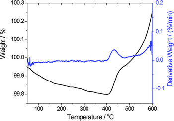
As TE devices are subjected to thermal cycling, we used TGA to locate temperatures of various thermal decomposition processes and to determine the amounts of volatiles. Results for a Bi2Te3 sample are shown in Fig. 1.
TGA thermogram and its derivative for Bi2Te3.

Figure 1 shows a slight mass loss (note the left scale) up to 400 °C. There is a steeper slope (wt%/°C) in the mass loss up to ∼160 °C and this is likely due to desorption and evaporation of absorbed residues such as moisture. The mass loss slope is more gradual from ∼160 to ∼400 °C and this may be due to sublimation of tellurium. However, starting at approximately 400 °C the diagram shows relatively sharp weight gain. Apparently a chemical reaction with something from the environment takes place. If tellurium is escaping, then oxidation of bismuth is a likely candidate for that reaction. This hypothesis is tested below by other means. Given the heating rate of 10 °C/min and the sharply upward trend of the curve, the oxidation reaction has not been completed during the run.
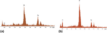
To evaluate the sublimation and oxidation hypotheses formulated above, we have applied EDS to n-type Bi2Te3 samples before [Fig. 2(a)] and after [Fig. 2(b)] the TGA examination.
EDS results: n-type Bi2Te3 (a) and n-type Bi2Te3after a TGA run (b).

We note 0.4 to 1.3 wt% oxygen at different sample areas of an unheated Bi2Te3 specimen prior to TGA. This implies different levels of initial oxidation during the production or storage period possibly caused by a nonuniform distribution of defects in Bi2Te3 crystals. Areas with large defects might provide high oxidation levels. The oxygen peak in Fig. 2(b) shows oxidation occurred during the TGA run. The ratio of the Te peak to the Bi peak after the run is smaller and the small 1.4 keV Se peak in 2(a) is absent in 2(b). We recall that n-type Bi2Te3 alloys typically contain Se. These data suggest a loss of Te and Se during heating of the Bi2Te3; a plausible explanation is sublimation.
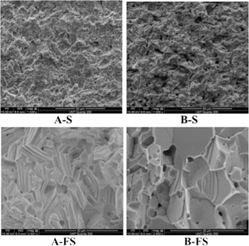
We have also studied morphology changes caused by heating using scanning electron microscopy (SEM); see Fig. 3. Samples were heated in a TGA apparatus up to 550 °C.
ESEM micrographs of Bi2Te3surfaces (S) and fractured surfaces (FS) before (A–S, A–FS) and after TGA testing (B–S, B–FS).

We see in Fig. 3 hollow microstructures caused by heating—a result of sublimation. The empty domains and degradation of the crystalline structure are more visible on the fractured surfaces, a darker color possibly a sign of oxidation. Thus, also environmental scanning electron microscopy (ESEM) images support our hypotheses on oxidation and sublimation of Bi2Te3components during heating.
IV. ELECTRICAL RESISTIVITY
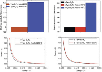
We now consider effects of heating on the electrical resistivity. Both n-type and p-type Bi2Te3 samples were left at either 250 or 500 °C for an hour. Then electrical resistivity was determined at 25 °C for each sample; see the results in Fig. 4. The current versus voltage diagrams are also included in that figure.
Electrical resistivity of n-type and p-type Bi2Te3before and after heating at 250 and 500 °C.

As expected, the resistivity values decrease with higher heating temperature in all cases. Compared with initial specimens, the resistivity values of both types of Bi2Te3samples are slightly higher after 1 h of heating at 250 °C temperature and much higher after heating to 500 °C. These results are also in agreement with our model of sublimation and oxidation. We have seen above manifestations of these processes in TGA, EDS and ESEM. Clearly metal sublimation and/or oxidation at high temperatures increase electric resistivity.
V. ENCAPSULATED MATERIALS
The key question is how to extend the service life of TE devices. Our approach is based on using a coating to insulate free spaces inside the TE devices and also to encapsulate both p-type and n-type TE materials. We thus expect to alleviate several problems listed above: moisture will not have easy access to interior of the device; structural integrity will be enhanced; corrosive agents will not have easy access; temperature cycling will not cause fast degradation, in particular sublimation will be eliminated; low thermal conductivity of the added materials will ensure concentration of heat flow through the TE device. The overall desired results will be TE systems operating at high temperatures with improved performance and longer lifetime.
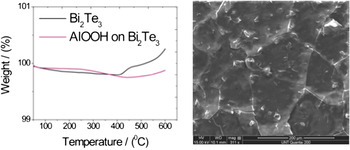
An inorganic ceramic coating could accomplish the above objectives–as mentioned previously. Bi2Te3specimens were coated with boehmite via dip coating and dried at 250 °C for 12 h to provide smoother surfaces.
Figure 5 shows that Bi2Te3 coated with boehmite displays better thermal stability all the way up to 600 °C than the bare Bi2Te3. Below 400 °C the coating prevents sublimation. However, above 350 °C we see a slight weight gain. ESEM analysis shows formation of cracks and it is likely that oxygen penetrates inside through the cracks and chemically reacts with Bi2Te3 components. The main reason for cracking of the ceramic coating seems to be the coating thickness exceeding 1 μm. We have to apply fairly thick coatings because of relatively rough surface of the unencapsulated Bi2Te3substrate. The minimum roughness was ≈0.78 μm, the maximum ≈1.16 μm. The n-type material has higher roughness than the p-type.
Bi2Te3+ AlOOH sample: (a) TGA and (b) ESEM.

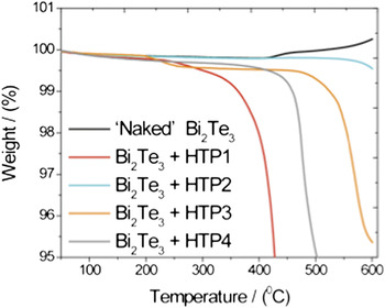
Given the results obtained with a ceramic coating, we moved to polymeric coatings. Expected advantages of HTPs for encapsulation of TE materials are flexibility, easiness of processing and ability to tailor properties through chemical modification or fillers. However, pitfalls are also possible. We are dealing here with the coating very different from the substrate. As discussed by Kopczynska and EhrensteinReference Kopczynska and Ehrenstein28 and more in detail in a book by Desai and Kapral,Reference Desai and Kapral29 properties of multiphase composites are strongly controlled by interfaces. Even interfacial curvatures are important.Reference Desai and Kapral29 Diffusion of moisture, gases or liquids across ceramic surfaces can be neglected for most purposes while such diffusion is fairly typical for polymersReference Hedenqvist, Johnsson, Tränkner and Gedde30–Reference Nilsson, Gedde and Hedenqvist32 and usually causes swelling.Reference Mark33–Reference Abdel-Azim, Abdul-Raheim, Atta, Brostow and Datashvili35 As before, we first used TGA for evaluation of four different HTP coatings; see Fig. 6.
TGA thermograms of “naked” and encapsulated Bi2Te3.

Note the small scale in Fig. 5 starting at 95%. As demonstrated above, Bi2Te3loses weight in temperatures up to 400 °C and then begins to gain weight through oxidation around 400 °C. The encapsulated samples show good thermal stability and lack of oxidation.
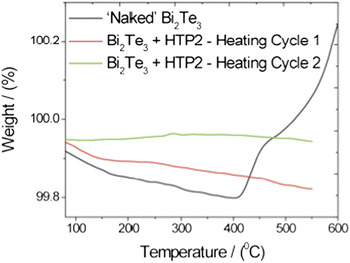
Subsequently, Bi2Te3 encapsulated with HTP2 was heated twice to 500 °C and each time left for 5 min at 500 °C. The respective TGA results are shown in Fig. 7; again note the scale, beginning here at 99.8%. In the second heating cycle there is hardly any change of weight; the volatiles were eliminated in the first cycle. Two cycles up to 500 °C have not caused thermal degradation, sublimation or oxidation of the TE material.
TGA thermograms: “naked” and encapsulated Bi2Te3samples after two heating cycles.

We find that encapsulating Bi2Te3 TE material with HTPs provided proof of concept for the capability to extend the service life of TE devices at high temperatures up to 550 °C. This provides a solution for Bi2Te3 TEGs with their relatively low operating temperature of 250 °C and it opens possibilities for applications with the higher temperature TE materials such as PbTe and skutterudite antimonides. We have used HTPs and their blends, but there are also other options including polymer irradiationReference Adhikari, Henning and Michler36, Reference Bobovitch, Gutmann, Henning and Michler37 or using fillers.Reference Nogales, Broza, Roslaniec, Schulte, Sics, Hsiao, Sanz, Garcia Gutierrez, Rueda, Domingo and Ezquerra38–Reference Michler and Balta-Calleja44 The last option should enable adjustment of thermal expansivity.
ACKNOWLEDGMENTS
Partial financial support from the II–VI Foundation, Bridgeville, PA, is gratefully acknowledged. Support to one of us (L.S.) by the Texas Academy of Mathematics and Science (TAMS), Denton, is acknowledged also.