Introduction
Cronstedtite is a 1:1 or TO phyllosilicate belonging to the kaolinite-serpentine group. Cronstedtite was discovered by Steinmann in 1821 and named in honor of the Swedish mineralogist Axel Fredrik Cronstedt (1722–1765). It is the trioctahedral serpentine richest in iron.
The general formula of cronstedtite is (Fe(II)3–x Fe(III) x)(Si2–x Fe(III) x)O5(OH)4 where x represents IVFe(III) and 0 < x < 1 (Hybler et al., Reference Hybler, Petříček, Ďurovič and Smrčok2000). The formula suggests that presumably the amount of VIFe(III) is equal to IVFe(III) to balance the charge deficit in tetrahedra due to the substitution of Si4+ by Fe(III). The maximum value of x is ideally 1, and the minimum value is 0, resulting in the formula of greenalite. Greenalite is another Fe-rich TO phyllosilicate, which differs from cronstedtite by the absence of Fe in the tetrahedral sites; it can, however, contain both Fe(II) and Fe(III) in the octahedral sites although Fe(II) is dominant (Guggenheim et al., Reference Guggenheim, Bailey, Eggleton and Wilkes1982). Observed values of x in cronstedtite range from ~0.5 to 0.8 (Hybler et al., Reference Hybler, Petřiček, Fábry and Ďurovič2002; Hybler et al., Reference Hybler, Sejkora and Venclík2016; Hybler et al., Reference Hybler, Dolníček and Sejkora2021a).
Si can be also replaced by small amounts of Al in addition to Fe (Hybler et al., Reference Hybler, Petříček, Ďurovič and Smrčok2000; Hybler et al., Reference Hybler, Petřiček, Fábry and Ďurovič2002; Pignatelli et al., Reference Pignatelli, Mugnaioli, Hybler, Mosser-Ruck, Cathelineau and Michau2013). Octahedral Fe(II) can be replaced by Mn(II) and/or Mg (e.g. Hybler and Sejkora, Reference Hybler and Sejkora2017; Hybler et al., Reference Hybler, Dolníček and Sejkora2021a; Hybler et al., Reference Hybler, Dolníček, Sejkora and Števko2021b).
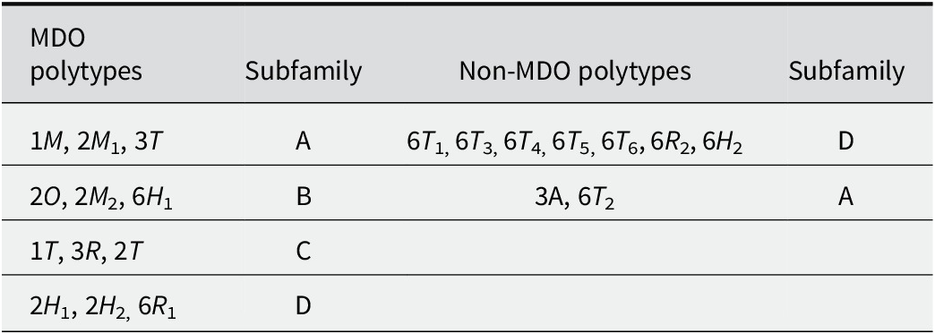
Like all phyllosilicates, cronstedtite displays polytypism, which is more complex than in micas (Nespolo and Ďurovič, Reference Nespolo and Ďurovič2002). The TO layers of cronstedtite can not only take six possible orientations, rotated by n60° (0 ≤ n ≤ 5) about the normal to the layer, but the absence of interlayer cations allows them to be shifted as well. The order-disorder (OD) theory (Dornberger-Schiff, Reference Dornberger-Schiff1956; Dornberger-Schiff, Reference Dornberger‐Schiff1979; Dornberger-Schiff and Ďurovič, Reference Dornberger-Schiff and Ďurovič1975a; Dornberger-Schiff and Ďurovič, Reference Dornberger-Schiff and Ďurovič1975b) classifies cronstedtite polytypes in four subfamilies, on the basis of shifts and/or rotations of consecutive, almost identical layers: ±a i/3 shifts for subfamily A, ±a i/3 shifts combined with 180° rotation for subfamily B, ±b/3 shifts or no shift for subfamily C, and ±b/3 shifts or no shift combined with 180° rotation for subfamily D. The a i and b are hexagonal and orthohexagonal axes, respectively. These subfamilies correspond to Bailey’s groups labelled with the same letters (Bailey, Reference Bailey1969; Bailey, Reference Bailey1988). Note that no polytype of subfamily B has been found to date (Hybler et al., Reference Hybler2016). Each subfamily groups several maximum degree order (MDO) polytypes, i.e. polytypes in which all layer triples, quadruples, etc., are geometrically equivalent or, when this is not possible, they contain the smallest possible number of kinds of n-tuples of layers (Dornberger-Schiff et al., Reference Dornberger-Schiff, Backhaus and Ďurovič1982). The MDO polytypes and their subfamily are listed in Table 1.
MDO and non-MDO polytypes of cronstedtite (represented with Ramsdell notation)

Table 1. Long description
Starting from the top row, the first column lists MDO polytypes: 1 M, 2 M 1, 3 T, . The second column assigns these to subfamily A. The third column lists non-MDO polytypes: 6 T 1, 6T 3, 6T4, 6T 5, 6T 6, 6R 2, 6H 2, with subfamily D in the fourth column. The second row contains MDO polytypes: 2 O, 2 M 2, 6H 1, assigned to subfamily B. The non-MDO polytype 3 A and 6T 2 are paired with subfamily A. The third row lists MDO polytypes: 1 T, 3 R, 2 T, assigned to subfamily C; the non-MDO columns are empty. The fourth row lists MDO polytypes: 2 H 1, 2H 2, 6R 1, assigned to subfamily D; the non-MDO columns are empty.
Several non-MDO polytypes of cronstedtite have been identified in the past (Table 1). The first was the 9R polytype described by Frondel (Reference Frondel1962), for samples from Cornucopia Mines (Nevada, USA), and Cornwall (England). Recently, Hybler et al. (Reference Hybler, Klementová, Jarošová, Pignatelli, Mosser-Ruck and Ďurovič2018) discovered an apparently ninetuple polytype interpreted as 3A in synthetic cronstedtite. If an incomplete diffraction pattern of this polytype were recorded, it could be interpreted as the nine-layered rhombohedral polytype described by Frondel (Reference Frondel1962). Twinning can also simulate a similar pattern; thus, the identification of the 9R polytype remains doubtful due to a lack of further details in the work published by Frondel (Reference Frondel1962). Cronstedtite from Morocco is particularly rich in non-MDO polytypes with six layers (Hybler et al., Reference Hybler, Dolníček, Sejkora and Števko2021b), including: 6T 1, 6T 2 polytype already discovered a few years earlier at Litošice (Hybler et al., Reference Hybler2016; Hybler, Reference Hybler2016), 6T 3, 6T 4, 6T 5, and 6T 6. In addition, new non-MDO polytypes, 6R 2 and possibly 6H 2, were observed from this locality, as well as 6R 1 predicted by Steadman and Nuttall (Reference Steadman and Nuttall1963) but never found before (Hybler et al., Reference Hybler, Dolníček, Sejkora and Števko2021b). The uncertainty about the discovery of the 6H 2 polytype results from the fact that its diffraction pattern is geometrically indistinguishable from that produced by a twinned 6R 2 polytype with a rotation by 180° about the [001]* axis.
Twinning has been described for a few cronstedtite polytypes: 1M crystals twinned by reticular merohedry with a 120° rotation along the [001]* axis have been found in natural and synthetic samples (Hybler et al., Reference Hybler, Klementová, Jarošová, Pignatelli, Mosser-Ruck and Ďurovič2018; Hybler et al., Reference Hybler, Dolníček, Sejkora and Števko2020); a 2M 1 polytype twinned by reticular pseudo-merohedry was observed in samples from Morocco (Hybler et al., Reference Hybler, Dolníček, Sejkora and Števko2021b). A 3T polytype twinned by reticular merohedry was also found in samples from Chyňava and Nižná Slaná (Hybler and Sejkora, Reference Hybler and Sejkora2017; Hybler et al., Reference Hybler, Števko and Sejkora2017). Finally, rare twins by reticular merohedry were identified in a 6T 2 polytype (Hybler et al., Reference Hybler2016).
A peculiarity of cronstedtite is that it often forms allotwins, i.e. the oriented associations of two (or more) crystals differing only in their polytypic character (Nespolo et al., Reference Nespolo, Kogure and Ferraris1999). Several allotwins have been identified in natural cronstedtite samples coming from different localities (2H 1 + 2H 2, 1T + 3T, 3T + 1M), but the sample from Ouedi Beht (Morocco) is the richest one, containing 2M 1 + 1M, 2M 1 + 6T 2, 3T+ 6T 2, 6T 2 + 1M, 2M 1 + 3T, 2H 1 + 6T 4, 2H 1 + 6T 3, 2H 1 + 6T 1, and 2H 1 + 6R 2 allotwins (Hybler et al., Reference Hybler2016; Hybler and Sejkora, Reference Hybler and Sejkora2017; Hybler et al., Reference Hybler, Dolníček and Sejkora2021a; Hybler et al., Reference Hybler, Dolníček, Sejkora and Števko2021b). Allotwins 1T + 1M, and 3T + 2M 1 were first observed in meteorites (Müller et al., Reference Müller, Kurat and Kracher1979; Pignatelli et al., Reference Pignatelli, Mugnaioli and Marrocchi2018), but these have recently been reported in terrestrial samples from Litošice, and Ouedi Beht (Hybler et al., Reference Hybler, Dolníček and Sejkora2021a; Hybler et al., Reference Hybler, Dolníček, Sejkora and Števko2021b).
Hybler et al. (Reference Hybler, Števko, Dolníček and Sejkora2024) recently proposed the coexistence of three polytypes in an allotwin: 2H 2 + 2H 1 with a small amount of 6T 2. This result remains questionable because of diffuse streaks and weak reflections of 6T 2.
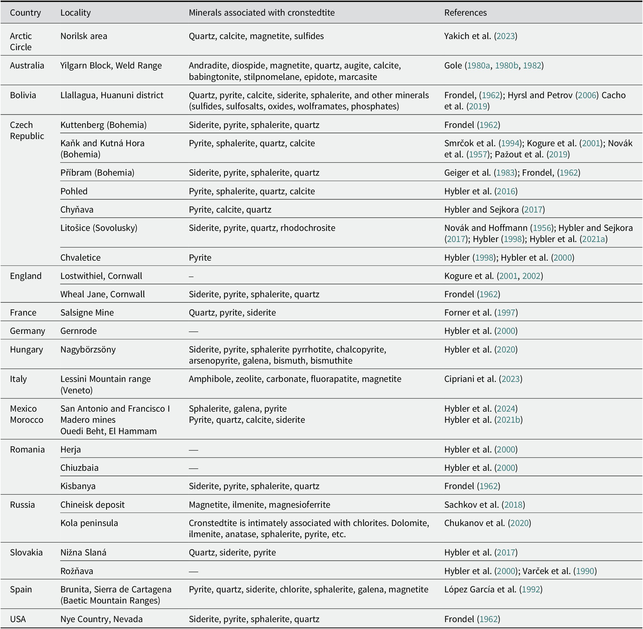
Cronstedtite has been found in terrestrial samples from several localities (Table 2), where it is generally associated with pyrite, quartz, siderite, and sometimes sphalerite. It is described as a supergene mineral crystallized in veins formed during low-temperature hydrothermal alteration (Frondel, Reference Frondel1962; López García et al., Reference López García, Manteca, Prieto and Calvo1992; Hybler and Sejkora, Reference Hybler and Sejkora2017; Hybler et al., Reference Hybler, Dolníček, Sejkora and Števko2020). Veins filled by cronstedtite occur in different geological contexts, such as skarn in Morocco and Mexico (Hybler et al., Reference Hybler, Dolníček, Sejkora and Števko2021b; Hybler et al., Reference Hybler, Števko, Dolníček and Sejkora2024) or mineralization in black shales formed as a product of volcanic activity and partially affected by metamorphism (Hybler et al., Reference Hybler, Dolníček and Sejkora2021a). Cronstedtite coexisting with greenalite has also been found in a low-temperature retrograde assemblage of an Archean banded iron formation in Western Australia (Gole, Reference Gole1980a; Gole, Reference Gole1980b; Gole, Reference Gole1982). This formation consists of andradite-diopside-magnetite mesobands alternating with quartz-rich mesobands also containing augite, and magnetite (Gole, Reference Gole1982).
Occurrences and minerals associated with cronstedtite (modified from Pignatelli et al., Reference Pignatelli, Mugnaioli, Mosser-Ruck, Abdelmoula and Sterpenich2024)

Table 2. Long description
The table has four columns: Country, Locality, Minerals associated with cronstedtite, and References. From the top row, the Arctic Circle (Norilsk area) lists quartz, calcite, magnetite, sulfides. Australia (Yilgarn Block, Weld Range) includes andradite, diospide, magnetite, quartz, augite, calcite, babingtonite, stilpnomelane, epidote, marcasite. Bolivia (Llallagua, Huanuni district) lists quartz, pyrite, calcite, siderite, sphalerite, and other minerals such as sulfides, sulfosalts, oxides, wolframates, phosphates. The Czech Republic has seven localities: Kuttenberg (Bohemia) with siderite, pyrite, sphalerite, quartz; Kaňk and Kutná Hora (Bohemia) with pyrite, sphalerite, quartz, calcite; Příbram (Bohemia) with siderite, pyrite, sphalerite, quartz; Pohled with pyrite, sphalerite, quartz, calcite; Chyňava with pyrite, calcite, quartz; Litošice (Sovolusky) with siderite, pyrite, quartz, rhodochrosite; Chvaletice with pyrite. England (Lostwithiel, Cornwall) has no minerals listed; Wheal Jane, Cornwall lists siderite, pyrite, sphalerite, quartz. France (Salsigne Mine) lists quartz, pyrite, siderite. Germany (Gernrode) and Romania (Herja, Chiuzbaia) have no minerals listed; Romania (Kisbanya) lists siderite, pyrite, sphalerite, quartz. Hungary (Nagybörzsöny) lists siderite, pyrite, sphalerite, pyrrhotite, chalcopyrite, arsenopyrite, galena, bismuth, bismuthite. Italy (Lessini Mountain range, Veneto) lists amphibole, zeolite, carbonate, fluorapatite, magnetite. Mexico and Morocco are combined: San Antonio and Francisco I Madero mines list sphalerite, galena, pyrite; Ouedi Beht, El Hammam lists pyrite, quartz, calcite, siderite. Russia (Chineisk deposit) lists magnetite, ilmenite, magnesioferrite; Kola peninsula lists cronstedtite with chlorites, dolomite, ilmenite, anatase, sphalerite, pyrite, etc. Slovakia (Nižna Slaná) lists quartz, siderite, pyrite; Rožňava has no minerals listed. Spain (Brunita, Sierra de Cartagena) lists pyrite, quartz, siderite, chlorite, sphalerite, galena, magnetite. USA (Nye Country, Nevada) lists siderite, pyrite, sphalerite, quartz. Each row includes references, with some rows citing multiple sources.
Cronstedtite can form in extraterrestrial environments and was detected by remote sensing techniques in some dark regions of Mars (Calvin, Reference Calvin1998), on the dwarf planet Ceres (Zolotov, Reference Zolotov2014). Cronstedtite has been described in CM chondrites, i.e. in the matrix and in fine-grained rims of the Cold Bokkeveld and Cochamba meteorites (Müller et al., Reference Müller, Kurat and Kracher1979; Zega and Buseck, Reference Zega and Buseck2003) or as pseudomorphs of olivine and pyroxene in the Paris meteorite (Pignatelli et al., Reference Pignatelli, Marrocchi, Mugnaioli, Bourdelle and Gounelle2017; Pignatelli et al., Reference Pignatelli, Mugnaioli and Marrocchi2018).
Cronstedtite has recently been synthesized successfully in order to understand its formation conditions and the physical-chemical parameters affecting its composition and structure (Pignatelli et al., Reference Pignatelli, Mugnaioli, Hybler, Mosser-Ruck, Cathelineau and Michau2013; Pignatelli et al., Reference Pignatelli, Mosser-Ruck, Mugnaioli, Sterpenich and Gemmi2020; Pignatelli et al., Reference Pignatelli, Mugnaioli, Mosser-Ruck, Abdelmoula and Sterpenich2024).
The aim of the present work was to characterize accurately cronstedtite crystals from the Salsigne mine (France) and to compare their chemical and polytypic features with those of crystals from other occurrences. In particular, the Fe(III)/Fe(II) ratio, the possibility of vacancies in the octahedral sheet, polytypism, and allotwinning were discussed.
Materials and methods
Geological setting
The Salsigne mine was one of the most important Au producers in western Europe, and other metals (Cu, Ag, As, Bi, Pb) were extracted from the Roman period until the 19th century (Demange et al., Reference Demange, Pascal, Raimbault, Armand, Forette, Serment and Touil2006). Mining operations ceased in 2004.
The Salsigne district is in the Montagne Noire, in the southern part of the French Massif Central, belonging to the same structural domain as the Pyrenees. It is made of four units separated by major thrust faults (Demange et al., Reference Demange, Issard and Perrin1986; Demange, Reference Demange1994): (1) the Neoproterozoic to Paleozoic Catalan domain; (2) the Occitan units, comprising Cambrian to early Carboniferous sedimentary rocks deposited along the northern margin of the Catalan domain; (3) the Albigeois units, Cambro-Ordovician sedimentary rocks of more distal character; and (4) the internal metamorphic units.
Orebodies including massive sulfide, and vein-type mineralization are hosted in the Axial zone of the Montagne Noire, along the major thrust separating the Catalan and Occitan units (called “3a/2x ore”) (Chiron and Forner, Reference Chiron and Forner1997; Demange et al., Reference Demange, Pascal, Raimbault, Armand, Forette, Serment and Touil2006).
This district recorded the entire tectonic evolution of the Montaigne Noire, marked by three main stages: early folding and regional metamorphism, emplacement of thrust nappes and post-nappe folding and faulting (Demange, Reference Demange1998; Demange, Reference Demange1999).
According to Demange et al. (Reference Demange, Pascal, Raimbault, Armand, Forette, Serment and Touil2006), a succession of nine hydrothermal events, commonly separated by tectonic events, is recognized. These authors reported that: ‘the first four stages, controlled by ductile to ductile-brittle structures synchronous with the emplacement of the nappes, were responsible for massive, and disseminated mineralization. They include (1) arsenopyrite-pyrrhotite-gold associated with biotite; (2) quartz-muscovite alteration; (3) massive sulfides (arsenopyrite-pyrrhotite-pyrite), and gold associated with chlorite; and (4) feldspathization. Subsequent stages, controlled by brittle tectonics that frequently reactivated earlier structures, include barren silicification, and quartz veins followed by four stages of sulfide precipitation separated by fracturing’.
Several orebodies are found in the Salsigne district and have been classified, on the basis of their morphology, into four types. One concerns orebodies along thrust surfaces and in the near shear zone, e.g. the body at the base of the Combe Bourrel thrust slice called ‘2x ore’ (Demange et al., Reference Demange, Pascal, Raimbault, Armand, Forette, Serment and Touil2006). Cronstedtite crystals come from this orebody, although they have been found in other orebodies referred to in French as ‘minerais traditional’, i.e. the orebody in the Minervois unit of the Fournes syncline, and along the thrust fault at the base of the Minervois nappe (Chiron and Forner, Reference Chiron and Forner1997; Forner et al., Reference Forner, Favreau, Meisser and Descouens1997). Cronstedtite was also observed in 1996 in a level of the open-pit mine on the ‘Croiseur Sud’ vein in the ‘2D schists’ and in the microcavities of ‘3a’ limestones (Forner et al., Reference Forner, Favreau, Meisser and Descouens1997).
Analytical methods
Scanning electron microscopy (SEM) was used to acquire back-scattered electron (BSE) images, and standardless energy dispersive X-ray (EDX) analyses by a cold-field emission gun (FEG) Hitachi S-4800 microscope operating with an accelerating voltage of 15 kV and a beam current of 10 nA.
μ-X-ray florescence (XRF) maps of thin sections of samples containing cronstedtite crystals were collected using a Bruker M4 Tornado spectrometer at the ITES-EOST of Strasbourg University. The system has a Rh X-ray tube operating at 50 kV and 200 μA. The beam is focused with polycapillary optics, providing a spot size of ~20 μm diameter. X-rays were detected by two energy dispersive spectrometers (EDS) 30 mm2 silicon drift detectors with an energy resolution of <135 eV at 250,000 cps (measured on MnKα). Data acquisition and processing were carried out using the Bruker software, ESPRIT, supplied with the instrument (Flude et al., Reference Flude, Haschke and Storey2017).
The chemical composition of cronstedtite was determined by electron microprobe analysis (EMPA) with a CAMECA SX100 microprobe, using an accelerating voltage of 15 kV, a beam current of 12 nA, and a probe diameter of 5 μm. The total iron content was reported as FeO. The microprobe was calibrated using the following standards: albite for Na, wollastonite for Si, hematite for Fe, San Carlos forsterite for Mg, corundum for Al, andradite for Ca, orthoclase for K, pyrophanite for Ti and Mn, chalcopyrite for Cu, topaz for F, sphalerite for Zn, vanadinite for Cl, and celestine for S.
In situ laser ablation inductively coupled plasma mass spectroscopy (LA-ICP-MS) quantitative analyses were performed using an Agilent 7900 quadrupole ICP-MS coupled with a 193 nm Excimer laser ESI NW193. A laser ablation point analysis was carried out with a laser operating at 10 Hz repetition rate and delivering a fixed fluence of 4 J cm–2, which generated ablation craters of 50 μm in diameter. The acquisition time for each point was 90 s, including 30 s of warm-up, 30 s of ablation, and 30 s of washout. He (700 mL min–1) was used to transport the laser-generated particles from the ablation cell to the mass spectrometer, and Ar was added as an auxiliary gas in front of the ICP torch. An averaged Si value obtained from EMPA (Table S1, Supplementary material), and certified reference materials NIST SRM 610 and 612 (Jochum et al., Reference Jochum, Weis, Stoll, Kuzmin, Yang, Raczek, Jacob, Stracke, Birbaum, Frick, Günther and Enzweiler2011) were used as internal and external standards, respectively. Uncertainty was calculated as a function of the uncertainty of external standards, absolute element content and integration time. The limits of detection (LOD) were calculated using the Longerich methodology (Longerich et al., Reference Longerich, Jackson and Günther1996). Iolite version 4 (https://iolite.xyz) was used for data reduction.
Several crystals were powdered and analyzed by Mössbauer spectroscopy to quantify the Fe(III)/Fe(II) ratio in cronstedtite. An appropriate quantity of sample (10 mg of Fe per cm2) was used to obtain optimal experimental conditions. The sample was prepared under an N2 atmosphere in a glove box and spread across a sample holder placed in an airtight blister pack. The Mössbauer spectrum was collected in transmission mode at 35 K with a constant-acceleration spectrometer over the energy range of ±4 mm s–1 and a 512 multi-channel analyzer (Halder Electronic Gmbh, Germany). The 50 mCi source of 57Co in a Rh matrix was maintained at room temperature and was mounted at the end of a Mössbauer velocity transducer. The spectrometer was calibrated with a 25 μm foil of α-Fe at room temperature. Analysis of the Mössbauer spectrum consisted of least-squares fitting of the data to a combination of two-peak quadrupole components (doublets). Computer fitting of the Mössbauer spectrum was performed using Recoil software (Lagarec and Rancourt, Reference Lagarec and Rancourt1998) with Lorentzian shape lines for paramagnetic sites (Recoil Software, Ottawa University). The hyperfine parameters are reported as CS (center shift) and Δ (quadrupole splitting). For minerals, these were largely determined empirically from Mössbauer spectra using software with a variety of different physical models. This generates model spectra to be compared with measured spectra (Murad and Cashion, Reference Murad and Cashion2003).
Cronstedtite crystals were glued onto glass fibers and examined using a four-circle (double wavelength) X-ray diffractometer Gemini A Ultra instrument (Rigaku Oxford Diffraction) equipped with a CCD area detector Atlas S2 at the Institute of Physics, Czech Academy of Sciences. MoKα radiation (λ = 0.7107 Å) with a graphite monochromator and a Mo-enhanced fiber-optics collimator were used. The Oxford diffraction package CrysAlisPro (Rigaku, 2018) was used for data collection, unit-cell determination, and data reduction. The ‘unwrap’ procedure of this package for generating the reciprocal sections facilitated recognition of the polytypes and allotwins with the help of identification diagrams (Hybler et al., Reference Hybler, Dolníček and Sejkora2021a,Reference Hybler, Dolníček, Sejkora and Števkob). A total of 49 crystals were measured (Table S2, Supplementary material).
Geometry of diffraction patterns and polytype identification
Three types of reflections were distinguished:
-
- 00l called ‘family reflections’ and common to all polytypes of all subfamilies, so they cannot be used to identify a polytype;
-
- h–k = 3n (hexagonal indices): these are common to all polytypes of the same subfamily, thus they are termed ‘subfamily reflections’;
-
- h–k ≠ 3n (hexagonal indices) are typical of each polytype and are termed ‘non-family reflections’, ‘polytype reflections’ or ‘characteristic reflections’.
The family and subfamily reflections are sharp even if the polytype is disordered, whereas non-family reflections can be streaked or broadened due to stacking disorder. However, chemical (substitutional) disorder can also affect other reflections, resulting in asymmetric broadening (Guinier et al., Reference Guinier, Bokij, Boll-Dornberger, Cowley, Ďurovič, Jagodzinski and Abrahams1984).
At least two diffraction patterns corresponding to two reciprocal planes obtained by reconstruction of reciprocal space are required to identify a polytype (Ďurovič, Reference Ďurovič1997). Reciprocal lattice rows
$ {[11l]}^{\ast }/{[2\overline{1}l]}^{\ast }/[\overline{1}2l]{{}^{\ast}}_{\mathrm{hex}} $
 in
$ (hhl{)}^{\ast }/{(2h\overline{h}l)}^{\ast }/(\overline{h}2hl){{}^{\ast}}_{\mathrm{hex}} $
 allow determination of the subfamily.
$ (h0l{)}^{\ast }/{(0kl)}^{\ast }/(\overline{h}hl){{}^{\ast}}_{\mathrm{hex}} $
 contains both subfamily and non-family reflections, thus the rows
$ {[10l]}^{\ast }/{[01l]}^{\ast }/[\overline{1}1l]{{}^{\ast}}_{\mathrm{hex}} $
 are useful to identify the polytype. Note that for non-trigonal and non-hexagonal polytypes, such as 1M, the diffraction patterns of
$ (hhl{)}^{\ast}\mathrm{a}\mathrm{n}\mathrm{d}{(\overline{h}hl)}^{\ast } $
 are not symmetrically equivalent, and both should be recorded and checked for polytype identification.
For known polytypes, identification diagrams constructed for a visual comparison with diffraction patterns are available in the literature (Ďurovič, Reference Ďurovič1981; Ďurovič, Reference Ďurovič1997; Hybler et al., Reference Hybler, Klementová, Jarošová, Pignatelli, Mosser-Ruck and Ďurovič2018). These have been updated recently after the discovery of new cronstedtite polytypes, and they are valid for all trioctahedral serpentines (Hybler et al., Reference Hybler, Dolníček, Sejkora and Števko2021b).
Results and Discussion
Sample description
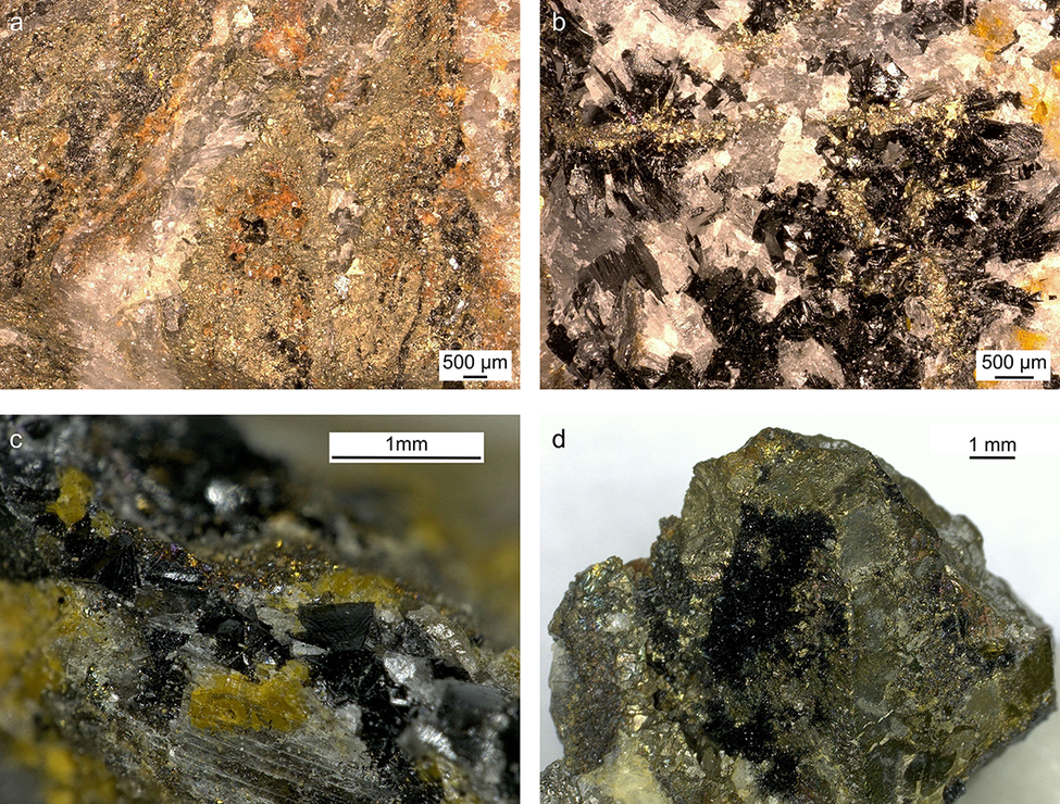
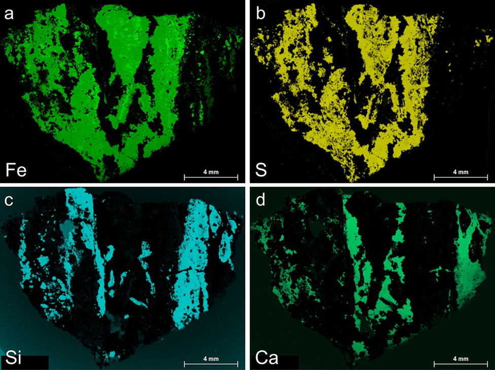
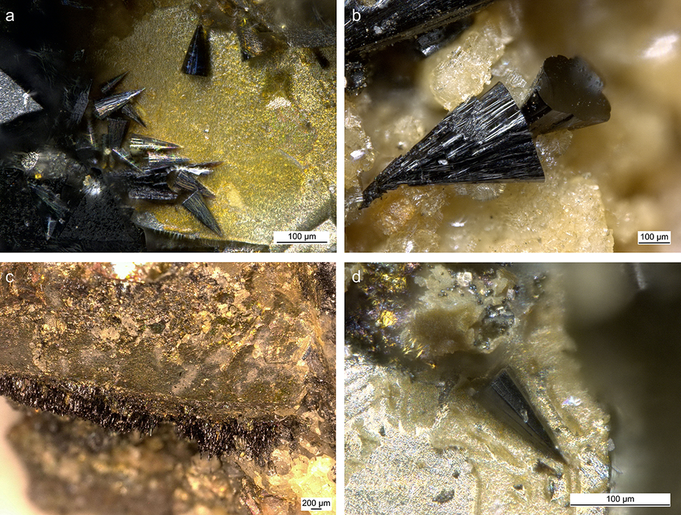
The cronstedtite crystals analyzed in the present study come from the private collection of one of the authors (C.L.). The crystals were not collected in situ but are from material excavated in 2005, as access to the mine has been forbidden since its closure in 2004. Macroscopically, cronstedtite is associated with pyrite, calcite, quartz, and siderite (Fig. 1). The association of sulfides, carbonates, and silicates (quartz and cronstedtite) is confirmed by μ-XRF maps (Fig. 2). Most of the crystals are trigonal pyramids (truncated or not – Fig. 3), but we also observed elongated crystals with a triangular cross-section. Smaller acicular crystals appear to form from the pyrite surface (Fig. 3c).
Optical images (a to d) of samples from which cronstedtite crystals were selected, showing the association of cronstedtite, pyrite, calcite, quartz, and siderite.

Figure 1. Long description
The top left panel labeled a shows a granular mineral matrix with dispersed orange, gold, and white regions, scale bar 500 micrometers. The top right panel labeled b displays a denser aggregation of black, gold, and white crystals, also at 500 micrometers. The bottom left panel labeled c presents a close-up of black prismatic crystals intergrown with yellow and white minerals, scale bar 1 millimeter. The bottom right panel labeled d features a hand specimen with a central cluster of black crystals surrounded by metallic gold and brown minerals, scale bar 1 millimeter. Each panel highlights the spatial relationship and textural contrast among cronstedtite, pyrite, calcite, quartz, and siderite.
μ-XRF maps showing the distribution of: (a) Fe, (b) S, (c) Si, and (d) Ca in a thin section.

Figure 2. Long description
The top-left panel labeled Fe shows a green distribution with high intensity in the central and left regions, forming a branching pattern. The top-right panel labeled S displays a yellow distribution, closely matching the Fe pattern but with slightly more dispersed regions. The bottom-left panel labeled Si presents a cyan distribution, concentrated in vertical bands along the left and right edges, with minimal presence in the center. The bottom-right panel labeled Ca shows a teal distribution, also forming vertical bands but with broader coverage than Si, especially along the right edge. All panels include a 4 mm scale bar in the lower right corner. The spatial relationships highlight complementary and contrasting elemental zoning within the thin section.
Optical images (a to d) showing the habit of cronstedtite crystals from Salsigne.

Figure 3. Long description
The composite photomicrograph is divided into four panels. In the top-left panel labeled a, several dark, elongated, prismatic cronstedtite crystals radiate outward from a yellowish mineral matrix, with a scale bar indicating 100 micrometers. The top-right panel labeled b shows a close-up of a single, fan-shaped, dark cronstedtite crystal with radiating striations, embedded in a granular, beige matrix, also with a 100 micrometer scale bar. The bottom-left panel labeled c displays a dense, horizontal layer of fine, dark, needle-like cronstedtite crystals forming a crust along the boundary of a brownish mineral substrate, with a scale bar of 200 micrometers. The bottom-right panel labeled d presents an isolated, sharply pointed, dark prismatic crystal on a pale, granular background, with a 100 micrometer scale bar. Each panel highlights different crystal morphologies and associations within the host rock.
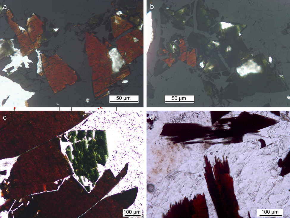
Under plane-polarized light in thin section, the pleochroism varies from green to reddish-brown (Fig. 4) because of the presence of both ferric and ferrous iron. The basal sections are always green when turning the microscope plate. Due to the intense pleochroism, the interference colors cannot be determined under cross-polarized light. However, the shape of their section allows them to be distinguished from pyrite (being opaque without any diagnostic feature under the transmitted light microscope). A thin rim of brown iron oxides/hydroxides surrounds carbonates in some areas of the thin sections.
Images of thin sections under plane-polarized light (a to d) showing the typical pleochroism of cronstedtite varying from green to reddish-brown.

Figure 4. Long description
Panel a at top-left shows angular cronstedtite grains with reddish-brown coloration and some white reflective areas, scale bar 50 micrometers. Panel b at top-right displays the same field as panel a but with more greenish hues visible in the grains, also with a 50 micrometer scale bar. Panel c at bottom-left presents a close-up of a large grain with a sharp transition from green to reddish-brown, scale bar 100 micrometers. Panel d at bottom-right shows elongated, blade-like grains with intense reddish-brown color and a white matrix, scale bar 100 micrometers. The panels illustrate the mineral’s pleochroism, with color changes depending on orientation under plane-polarized light.
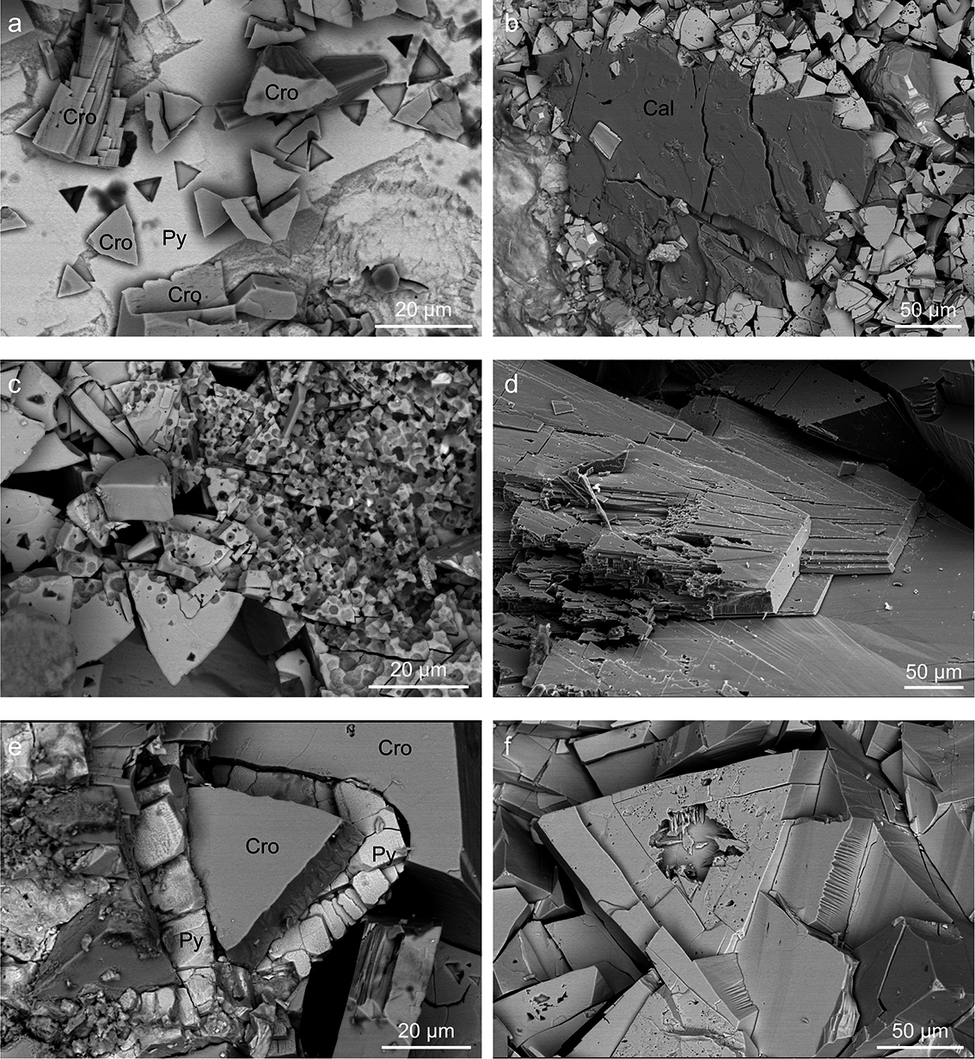
Observations using SEM indicated that cronstedtite crystals are affected by different degrees of etching: some crystals show triangular etch pits on basal planes whereas others are almost completely dissolved and look like a ‘gruyere cheese’ (Fig. 5). This suggests that something changed during crystal growth, and the mineral was no longer in equilibrium. It is possible that the composition, and/or redox state of mineralizing fluids evolved over time. The SEM images also show that the pyrite surfaces have triangular cavities mimicking the shape of cronstedtite. These could represent empty spaces left by cronstedtite crystals that were removed during sample collection and/or preparation. If true, this would support the hypothesis of cronstedtite growth from the pyrite surface, in agreement with the optical observations (Fig. 3c). However, this suggestion is speculative as the location of cronstedtite formation in Salsigne mine is unknown.
BSE-SEM images: (a) cronstedtite (Cro) crystals on pyrite (Py); (b) calcite (Cal) surrounded by cronstedtite; (c, f) cronstedtite crystals with evidence of dissolution; (e) cronstedtite surrounded by pyrite crystals; and (d) SE-SEM image of cronstedtite cleavage.

Figure 5. Long description
Top left panel a shows angular cronstedtite crystals labeled Cro distributed across the field, with pyrite labeled Py near the center. Top center panel b features a large, blocky calcite crystal labeled Cal surrounded by smaller cronstedtite grains. Top right panel c displays cronstedtite crystals with irregular, pitted surfaces indicating dissolution. Bottom left panel d presents a close-up of cronstedtite cleavage, with stepped, plate-like layers. Bottom center panel e highlights a large cronstedtite crystal bordered by pyrite grains, both labeled Cro and Py, with pyrite forming a partial rim. Bottom right panel f shows a single cronstedtite crystal exhibiting surface dissolution pits and fractures. Scale bars in each panel indicate 20 or 50 micrometers.
Chemical composition
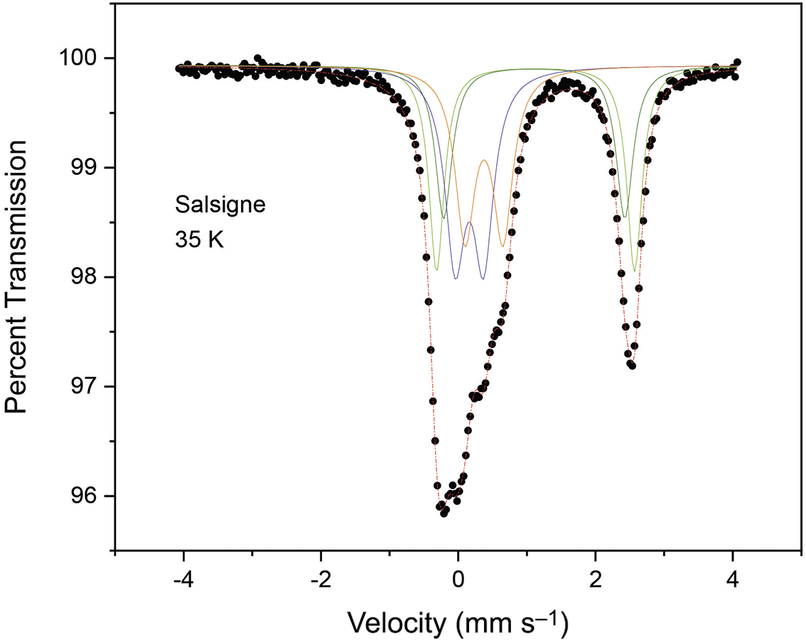
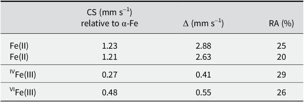
The EMPA data (Table S1, Supplementary material) revealed the chemical homogeneity of the cronstedtite crystals. These analyses were interpreted on the basis of ferrous iron, but cronstedtite is known to contain both Fe(III) and Fe(II), so a Mössbauer spectrum was also recorded (Fig. 6; Table 3). The Mössbauer spectrum was fit adequately with four quadrupole doublets, which can be classified into two categories according to their hyperfine parameters. Two with larger values of CS and Δ (see Table 3) are distinguished, along with both doublets with a small CS and Δ. The larger values of CS and Δ arise from Fe(II) in high-spin configuration, whereas the smaller values are characteristic of Fe(III). The distinction between the two ferric sub-components, with a distribution in tetrahedral and octahedral sites – the only two cation sites available in the 1:1 layer – is easily made on the basis of the chemical shift values (CS = 0.27 mm s–1 vs CS = 0.48 mm s–1; Table 3). The Mössbauer spectrum provides a relative abundance of 55% Fe(III) and 45% Fe(II). Considering an uncertainty of ±4%, it appears that this sample of cronstedtite contains approximately equal amounts of Fe(III) and Fe(II).
Mössbauer spectrum of cronstedtite from Salsigne, measured at 35 K.

Figure 6. Long description
The line graph plots percent transmission on the y axis, ranging from 96 to 100, against velocity in millimeters per second on the x axis, ranging from negative 5 to positive 5. Black dots represent measured data points. From left to right, the transmission remains near 100 percent at negative velocities, then sharply drops to a minimum near negative 1.5 millimeters per second, forming the first main absorption trough. Several colored lines, representing fitted component curves, overlap this region. The transmission rises again near zero velocity, then drops to a second minimum near positive 2 millimeters per second, forming the second main absorption trough, also with overlapping fitted curves. The transmission returns to near 100 percent at the highest velocities. The label ‘Salsigne 35 K’ appears in the upper left quadrant.
Hyperfine parameters obtained from the fit of a 35 K Mössbauer spectrum

Table 3. Long description
From the top row, Fe(II) is listed twice with CS values of 1.23 and 1.21 millimeters per second relative to alpha-Fe, Delta values of 2.88 and 2.63 millimeters per second, and relative abundances of 25 percent and 20 percent. The next row presents IVFe(III) with a CS of 0.27 millimeters per second, Delta of 0.41 millimeters per second, and relative abundance of 29 percent. The final row shows VIFe(III) with a CS of 0.48 millimeters per second, Delta of 0.55 millimeters per second, and relative abundance of 26 percent. Column headers are CS in millimeters per second relative to alpha-Fe, Delta in millimeters per second, and RA as percent relative abundance.
RA = relative abundance of Fe species.
The Fe(III)/Fe(II) ratio, the center shift (CS), and quadrupole splitting (Δ) values are close to those measured at 80 K by Coey et al. (Reference Coey, Bakas, McDonagh and Litterst1989) for natural cronstedtite crystals from Příbram (Czech Republic) and Wheal Jane (England), as well as to those for cronstedtite synthesized by Pignatelli et al. (Reference Pignatelli, Mugnaioli, Mosser-Ruck, Abdelmoula and Sterpenich2024).
Combining EMPA and Mössbauer data, the average formula (calculated on the basis of seven oxygen atoms) for the cronstedtite crystals from Salsigne is:

It follows that:
-
- the octahedral sites are not completely filled, and a small number of vacancies should be considered. This is the first time that vacancies have been reported for this mineral, probably because previous formulae were calculated without knowing the Fe(III)/Fe(II) ratio but rather adjusting it to set the cation occupancy of the octahedral sites to three. The same incongruity between the formula calculated only using EMPA data and that obtained from Mössbauer results is evident in the results of Coey et al. (Reference Coey, Bakas, McDonagh and Litterst1989). The present results are consistent with Hendricks (Reference Hendricks1939), who suggested that the total octahedral site occupancy in cronstedtite can be intermediate between two and three.
The same issue has been raised in the literature for micas, and the dichotomy ‘dioctahedral-trioctahedral’ was replaced by a more precise classification in ‘families’ on the basis of the cation, and vacancy distribution in the octahedral sites (Nespolo and Ďurovič, Reference Nespolo and Ďurovič2002).
-
- In the average formula, IVFe(III) is not equal to VIFe(III) as in the general formula (Fe(II)3–x Fe(III) x)(Si2–x Fe(III) x)O5(OH)4. The presence of vacancies and an amount of VIFe(III) greater than the expected value can be explained by analogy with wüstite, where the vacancies give rise to a non-stoichiometric formula Fe1–x O (with x ranging from 0.05 to 0.15) (Minervini and Grimes, Reference Minervini and Grimes1999).
The total positive charge in the formula is not balanced exactly, and it is slightly less than the total negative charge (Δcharge = –0.06). This difference could potentially be balanced by:
-
(1) Very small amounts of other cations such as Mg, Mn and Al (Table S1, Supplementary material). W, Pb, Zn, Cu, and Y are found as trace elements, whereas Au and Ag are below the detection limits of LA-ICP MS (Table S2, Supplementary material).
-
(2) An ‘Fe-oxy’ substitution may occur, similar to what has been observed in micas, where crystals rich in ferric iron also have greater oxygen content (Rancourt et al., Reference Rancourt, Mercier, Cherniak, Desgreniers, Kodama, Robert and Murad2001; Rieder et al., Reference Rieder, Cavazzini, D’yakonov, Frank-Kamenetskii, Gottardi, Guggenheim, Koval, Müller, Neiva, Radoslovich, Robert, Sassi, Takeda, Weiss and Wones1998).
To the best of the present authors’ knowledge, as an incomplete occupancy of tetrahedral site has never been reported to date, and there is no Al to replace Si (Tables S1 and S2, Supplementary material), the tetrahedra must be filled by Fe(III). For this reason, the proportion of IVFe(III) in the formula (23% of Fetot) is slightly different from the value obtained using Mössbauer spectroscopy (29%, Table 3). However, the difference between the two values (6%) is close to the uncertainty of ±4% in the Mössbauer data.
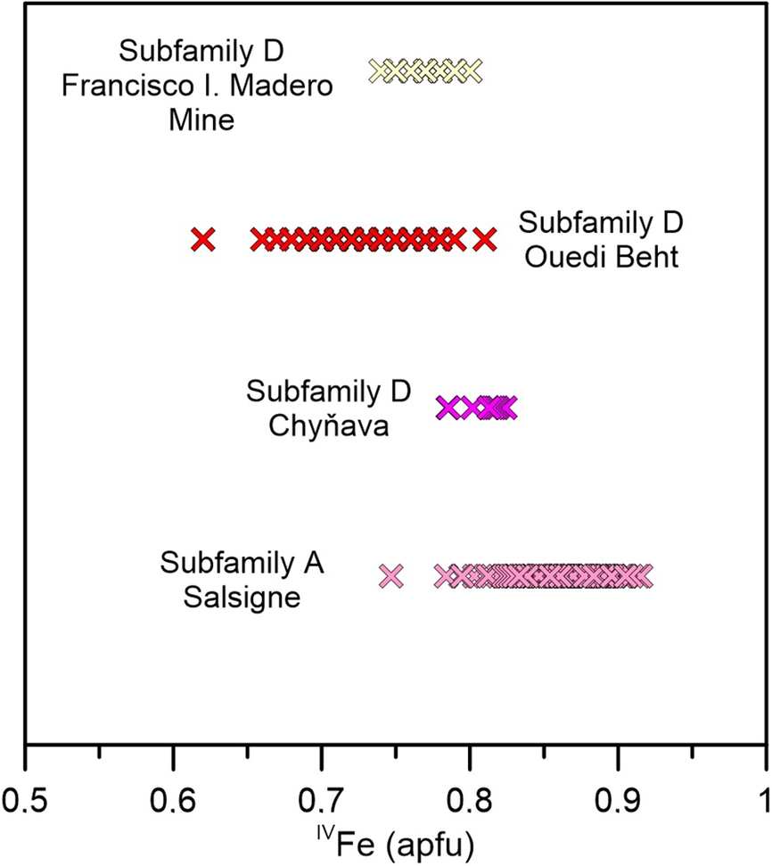
Literature values of IVFe(III), the so-called x-value, range from 0.56 to 0.86 atoms per formula unit (apfu). The highest value was found for cronstedtite from Litošice (Czech Republic) based on EMPA data (Hybler et al., Reference Hybler, Dolníček and Sejkora2021a; Hybler et al., Reference Hybler, Dolníček, Sejkora and Števko2021b). The lowest value of IVFe(III) = 0.56 apfu was reported for a 2H 2 cronstedtite polytype from Wheal Maudin (England), but this value was determined from structure refinement and was 0.15 apfu lower than that obtained by EMPA for the same crystal (Hybler et al., Reference Hybler, Petřiček, Fábry and Ďurovič2002).
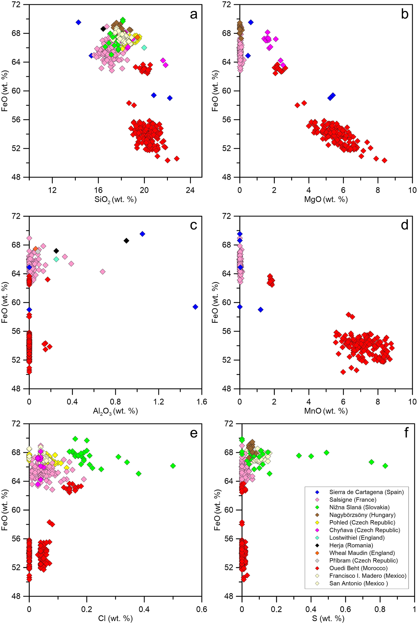
Previous studies have emphasized the relationship between polytype subfamilies, and the tetrahedral Fe content, namely that IVFe increases in the sequence C-A-D (Hybler and Sejkora, Reference Hybler and Sejkora2017; Hybler et al., Reference Hybler, Petříček, Ďurovič and Smrčok2000; Hybler et al., Reference Hybler, Petřiček, Fábry and Ďurovič2002; Hybler et al., Reference Hybler2016; Hybler et al., Reference Hybler, Števko and Sejkora2017). The IVFe content in cronstedtite from Salsigne is compared with those of polytypes of subfamily D from other localities, which are supposed to have the largest IVFe contents (Hybler and Sejkora, Reference Hybler and Sejkora2017). Contrary to expectations, the Salsigne cronstedtite is not consistent with this relationship, as the polytypes in Salsigne cronstedtite belong almost exclusively to subfamily A (see next paragraph). The IVFe(III) value in the cronstedtite crystals from Salsigne is between 0.75 and 0.92 apfu, approaching the maximum value of 1 and indicating that some crystals from Salsigne are those with the tetrahedral sites richest in iron (Fig. 7). Comparison with cronstedtite crystals from several localities emphasizes how chemically distinct the cronstedtite from Ouedi Beht (Morocco) is (Fig. 8), not only in terms of its Fe/Si ratio but also in relation to minor-element (Mn, Mg) and anion (Cl, S) contents (considered as OH substituents; Hybler et al., Reference Hybler, Dolníček, Sejkora and Števko2021b, Reference Hybler, Števko, Dolníček and Sejkora2024).
Comparison of x-values in cronstedtite crystals from Salsigne, and in polytypes belonging to subfamily D from Chyňava, Ouedi Beht, and Francisco I Madero.

Figure 7. Long description
The plot has four horizontal bands, each labeled at the left or right. From top to bottom, the first band is Subfamily D Francisco I Madero Mine, with pale yellow x-shaped points clustered between 0.7 and 0.8 on the x-axis. The second band is Subfamily D Ouedi Beht, with red x-shaped points spanning from about 0.6 to 0.9. The third band is Subfamily D Chynava, with magenta x-shaped points clustered between 0.7 and 0.8. The lowest band is Subfamily A Salsigne, with pink x-shaped points spanning from about 0.7 to 0.9. The x-axis is labeled IVFe (apfu), ranging from 0.5 to 1. The y-axis is divided into the four sample groups. Each group’s data points are horizontally aligned, showing the distribution of IVFe values for each locality and subfamily.
Compositional diagrams comparing the chemistry of Salsigne cronstedtite with the compositions of cronstedtite crystals found in other localities. The total iron content is reported as FeO. (a) FeO vs SiO2 wt.%; (b) FeO vs MgO wt.%; (c) FeO vs Al2O3 wt.%; (d) FeO vs MnO wt.%; (e) FeO vs Cl wt.%; (f) FeO vs S wt.%.

Figure 8. Long description
Top left panel a plots FeO weight percent on the y-axis from 48 to 72 against SiO2 weight percent on the x-axis from 12 to 24. Top center panel b plots FeO against MgO from 0 to 10. Top right panel c plots FeO against Al2O3 from 0 to 1.6. Bottom left panel d plots FeO against MnO from 0 to 10. Bottom center panel e plots FeO against Cl from 0 to 0.6. Bottom right panel f plots FeO against S from 0 to 0.6. Each panel contains colored diamond symbols representing different localities, as indicated in the legend in panel f: Sierra de Cartagena (blue), Salsigne (red), Nizna Slana (pink), Nagybörzsöny (green), Podel (brown), Chytrava (yellow), Lostwithiel (light green), Herja (black), Wheal Maudlin (light blue), Pribram (orange), Ouedi Beht (light brown), Francisco I. Madero (light green), San Antonio (light pink). Salsigne samples (red) cluster at lower FeO values and are distinct from other localities, which generally cluster at higher FeO values. The distribution and clustering patterns vary by panel, with Salsigne showing the widest spread in FeO and other elements, while other localities are more tightly grouped.
Cronstedtite from Chyňava (Slovakia) is also Mg-bearing but it is Mn-free (Hybler et al., Reference Hybler, Števko and Sejkora2017). It is not difficult to discern chemically the cronstedtites from Salsigne and Morocco using these elements. The relatively large amount of Mn+Mg in crystals from Morocco has been described as a transitional composition to guidottiite (Hybler et al., Reference Hybler, Dolníček, Sejkora and Števko2021b). The large amount of Mn+Mg in Moroccan cronstedtite is probably related to its unusual association with skarn ore material (Hybler et al., Reference Hybler, Dolníček, Sejkora and Števko2021b).
Cronstedtites from Nižna Slaná (Slovakia) and Pohled (Czech Republic) can be distinguished from those from Salsigne, although less easily, because their Fe/Si ratios are closer. Cronstedtite from Nižna Slaná is slightly richer in Si, whereas the larger amounts of S and Cl allow the identification of crystals from Pohled (Fig. 8). These differences probably reflect the formation conditions: cronstedtite from Pohled occurs in a hydrothermal vein developed in migmatized paragneiss near the contact with two-mica granite (Hybler et al., Reference Hybler2016), whereas cronstedtite from Nižna Slaná was found in pods of vuggy to drusy pyrite in a hydrothermal quartz vein that crosscut metasomatic siderite (Hybler et al., Reference Hybler, Števko and Sejkora2017). Cronstedtite from the Nagybörzsöny deposit, Hungary, contains more Fe and S than the Salsigne cronstedtite, although the geological context of the two localities is similar. The Nagybörzsöny deposit was also exploited for Au and Ag in the past, and cronstedtite formed under hydrothermal alteration in an argillite zone with local Au-bearing sulfide mineralization, where siderite and pyrite are the major constituents of the ore material (Hybler et al., Reference Hybler, Dolníček, Sejkora and Števko2020).
Polytypism and allotwinning
All polytypes found in the Salsigne samples belong to subfamily A, with the exception of 1T (subfamily C) occurring with the 3T polytype in an allotwin relation (Table S2, Supplementary material). The polytypes of subfamily A are mostly 3T and 1M, and they show different degrees of disorder.
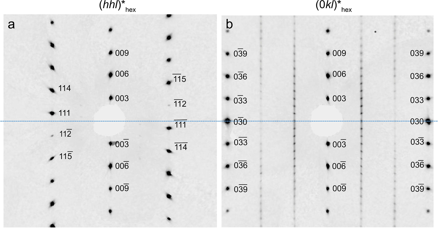
Figure 9 shows the (hhl)∗hex plane typical of subfamily A, whereas the (0kl)∗ plane shows the triple periodicity of the 3T polytype. Its unit-cell parameters are a = 5.49 Å and c = 21.25 Å, similar to those reported by Hybler et al. (Reference Hybler, Sejkora and Venclík2016, Reference Hybler, Števko and Sejkora2017) and Smrčok et al. (Reference Smrčok, Ďurovič, Petříček and Weiss1994) who refined the structure of the 3T polytype. 3T is one of the most frequent cronstedtite polytypes, together with 1T, 2H 1 and 2H 2 (Hybler and Sejkora, Reference Hybler and Sejkora2017). The 3T polytype was also found in the cronstedtite of the Paris meteorite (Pignatelli et al., Reference Pignatelli, Mugnaioli and Marrocchi2018).
Reciprocal sections of the 3T polytype. (a) (hhl)*hex is characteristic of subfamily A. (b) Reflections along [01l]* on (0kl)*hex show the three-layer periodicity typical of this polytype.

Figure 9. Long description
Panel a on the left shows a reciprocal section labeled (h h l)* hex, with a central blanked spot and two radiating sets of diffraction spots. Labels include 003, 006, 009, 111, 112, 114, and 115, with overbars indicating negative indices. Spots are symmetrically distributed above and below the center, with mirrored indices. Panel b on the right shows the (0 kl)* hex section, with vertical columns of spots labeled 003, 006, 009, 030, 033, 036, and 039, including overbarred indices. The spots are aligned in straight vertical lines, with each label mirrored on both sides of the central blanked spot. The arrangement in panel b highlights the three-layer periodicity by the regular spacing of the spots along the vertical axis.
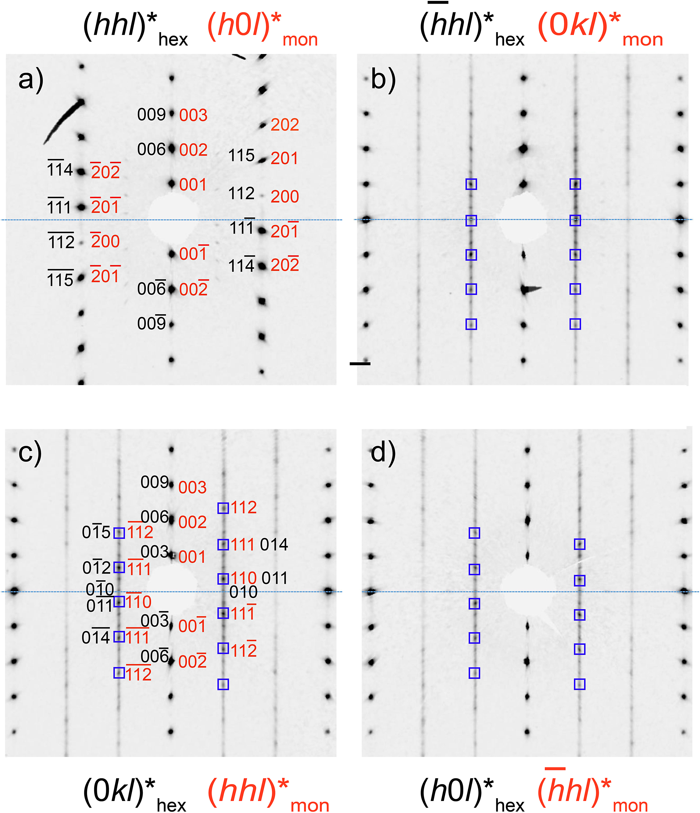
Polytype 1M (a = 5.50 Å, b = 9.53 Å, c = 7.31 Å, β = 104.6°; space group Cm) was identified in a specimen of Salsigne cronstedtite (Fig. 10) although the crystal was affected by stacking disorder, as indicated by diffuse scattering along c ∗. The reflection distribution along [11l]∗hex in (hhl)∗hex indicates that the subfamily is A, although two different planes must be considered to determine the polytype. The reflection distribution along [10l]∗hex in (h0l)∗hex, and that along [01l]∗hex in (0kl)∗hex correspond to MDO groups II and I on the polytype identification diagram, confirming that this polytype is 1M. It is often twinned by reticular pseudo-polyholohedry (Nespolo and Ferraris, Reference Nespolo and Ferraris2004a); in this case the twin index is 3 with ω = 0.08°, and the twin operation is a ±120° rotation about the [001]∗ axis. Reciprocal planes containing subfamily reflections are not affected by this twinning (Hybler et al., Reference Hybler, Klementová, Jarošová, Pignatelli, Mosser-Ruck and Ďurovič2018). The 1M polytype is rare in natural samples although it commonly occurs in synthetic materials (Hybler et al., Reference Hybler, Klementová, Jarošová, Pignatelli, Mosser-Ruck and Ďurovič2018; Pignatelli et al., Reference Pignatelli, Mosser-Ruck, Mugnaioli, Sterpenich and Gemmi2020).
Reciprocal sections of 1M polytype. (a) (h0l)*mon plane containing reflections of subfamily A (indexed with respect to the monoclinic cell of polytype); (b, c)
$ ( hhl){{}^{\ast}}_{\mathrm{mon}}\hskip2pt \mathrm{a}\mathrm{n}\mathrm{d}\hskip2pt (\overline{h}hl){{}^{\ast}}_{\mathrm{mon}} $
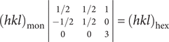
 planes are diagonal to the m plane; (d) (0kl)*mon plane perpendicular to the m plane. The corresponding hexagonal indexes are provided in red. The transformation matrix is:

because the monoclinic cell is C-centered and the hexagonal one is primitive; in addition the latter is triple the monoclinic cell.

Figure 10. Long description
Panel a at top-left shows the (h0 l)*mon plane with vertical rows of black spots labeled by monoclinic indices such as 003, 002, 001, 200, 201, 202, and their negatives, with corresponding hexagonal indices in red including 111, 112, 114, 115. Panel b at top-right displays the (hhl) mon and (0 kl)* hex planes, with diagonal and vertical spot arrays, black indices like 003, 002, 001, 011, 012, and red indices such as 033, 030, 011, 014, 036. Panel c at bottom-left shows the (-hhl)* mon and (h0 l)* hex planes, with vertical spot rows, black indices 003, 002, 001, 101, 102, 104, and red indices 300, 303, 104, 101, 102. Panel d at bottom-right presents the (0 kl)*mon and (hhl)*hex planes, with vertical and diagonal spot arrays, black indices 003, 002, 001, 110, 113, 333, and red indices 113, 333, 021, 060, 061, 110. The blue dashed line marks the central horizontal axis in all panels. Each panel’s title at the top specifies the reciprocal plane section, with monoclinic indices in black and hexagonal in red. The transformation matrix relating monoclinic and hexagonal indices is referenced in the caption.
1M and 3T polytypes can coexist in allotwins without affecting the distribution of subfamily reflections because both belong to the subfamily A (Fig. 11). The
$ {[\overline{1}1l]}^{\ast }/{[01l]}^{\ast }/[10l]{{}^{\ast}}_{\mathrm{hex}} $
 rows show the triple periodicity of the 3T polytype, but the intensities of reflections are modified by the presence of the 1M polytype. For the 3T polytype, the intensities along these rows decrease with increasing ǀlǀ, but reflections l = 3n, l = 3n+1, and l = 3n +2 of 3T become stronger in
$ (\overline{h}hl){{}^{\ast}}_{\mathrm{hex}},(0kl){{}^{\ast}}_{\mathrm{hex}},\mathrm{a}\mathrm{n}\mathrm{d}\hskip2pt (h0l){{}^{\ast}}_{\mathrm{hex}}, $
 respectively if 1M is also present (Hybler et al., Reference Hybler2016).
Reciprocal sections of a 3T + 1M allotwin. (a) (hhl)∗hex is characteristic of subfamily A. (b) The
$ (\overline{h}hl){{}^{\ast}}_{\mathrm{hex}} $
 plane shows the triple periodicity of 3T with the intensities of reflections l = 3n along
$ \left[\overline{1}1l\right]{\ast}_{\mathrm{hex}} $
 modified by the presence of 1M (indicated by the squares). (c) Similarly, reflections l = 3n +1 along [01l]∗ and l = 3n–1 along
$ {[0\overline{1}l]}^{\ast } $
 on (0kl)∗hex are stronger due to the presence of the 1M polytype. (d) The same modifications are visible on (h0l)∗hex for reflections l = 3n +2 along [10l]∗ and l = 3n–2 along
$ {[\overline{1}0l]}^{\ast } $
 .

Figure 11. Long description
Panel a, top-left, displays a reciprocal lattice section labeled (hhl)*hex and (h0 l)*mon, with black and red indices marking reflection spots. Panel b, top-right, shows (-hhl)*hex and (0kl)*mon kl, with vertical columns of black spots and blue squares highlighting selected reflections along two vertical lines. Panel c, bottom-left, presents (0kl)*hex and (hhl)*mon, with both black and red indices and blue squares marking certain spots, distributed symmetrically about the center. Panel d, bottom-right, shows (h0l)*hex and (-hhl)*mon , with vertical arrays of black spots and blue squares marking corresponding positions as in panel b. All panels share a central horizontal dashed blue line as a reference axis. The blue squares indicate reflections modified by the presence of the 1 M polytype, as described in the caption.
Literature data and the present results suggest that a 3T + 1M allotwin is common, as it has been reported in cronstedtite samples from several localities other than Salsigne: Pohled (Czech Republic), Ouebi Beth (Morocco), Nižná Slaná (Slovakia), and Nagybörzsöny (Hungary) (Hybler et al., Reference Hybler2016; Hybler et al., Reference Hybler, Števko and Sejkora2017; Hybler et al., Reference Hybler, Dolníček, Sejkora and Števko2020; Hybler et al., Reference Hybler, Dolníček, Sejkora and Števko2021b).
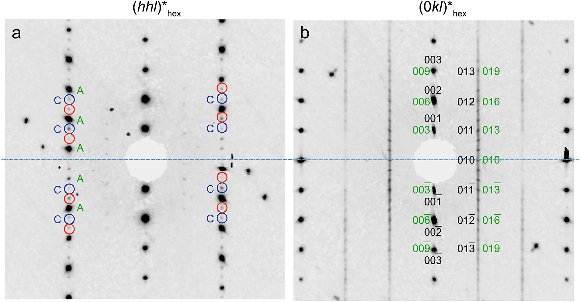
The 3T polytype forms allotwins with other polytypes, namely 2M 1, 6T 2, and 1T. The reciprocal (hhl)∗hex plane where reflections of both subfamilies A and C are present is shown in Fig. 12, although those of subfamily A are much stronger than the others. The 3T polytype can be identified (Fig. 12b) on the (0kl)∗hex plane. However, diffuse streaks, the weakness of reflections from subfamily C, and the presence of twinning make its identification more difficult. The 3T + 1T allotwin is rare in cronstedtite from Salsigne, and it was identified in only one crystal, representing the only occurrence of a polytype belonging to subfamily C.
Reciprocal sections of a 3T + 1T allotwin. (a) (hhl)*hex plane where reflections of both subfamilies A and C are present, although those of subfamily A are much stronger than the others. Reflections of subfamilies A and C are labelled. 1T is probably twinned by a 180° rotation: reflections of one individual are surrounded by blue circles, and remaining reflections are those of the second individual (red circles). (b) (0kl)*hex showing the three-layer periodicity of the 3T polytype. Indices of both 3T and 1T are reported in green and black, respectively.

Figure 12. Long description
The left panel shows the (hhl)*hex plane. At the center is a masked region. Moving outward, vertical columns of diffraction spots are visible. Reflections are labeled A and C in green and blue, with A reflections stronger. Blue and red circles surround C and A reflections, indicating two individuals related by a 180 degree rotation. The right panel shows the (0kl)*hex plane. At the center is a masked region. Vertical columns of spots are labeled with indices in green for 3 T and black for 1 T, including 003, 009, 002, 006, 001, 003, 010, 011, 012, 013, 016, 019, and their negative counterparts. The three-layer periodicity of the 3 T polytype is indicated by the green indices. All labels are arranged symmetrically about the central horizontal axis.
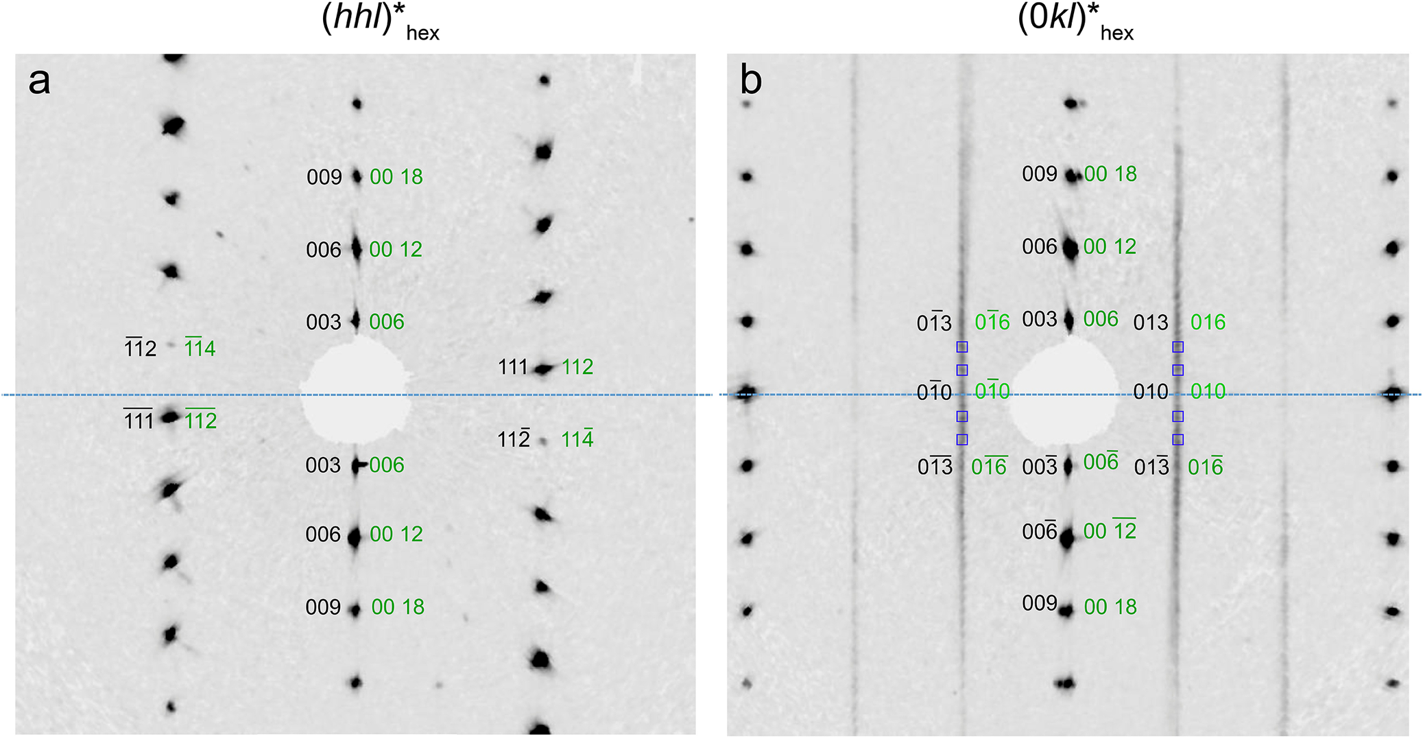
Polytypes 3T + 6T 2 have also been observed (Fig. 13). Both polytypes belong to subfamily A, and thus their coexistence is visible on reciprocal planes containing non-family reflections. Figure 13b shows the (0kl)∗hex plane where the six-layer multiplicity is evident along [01l]∗ despite the diffuse streaks. However, the intensities of reflections are modified by the presence of 3T, which makes every second reflection stronger. This allotwin sometimes contains extra reflections that could be due to another polytype or inclusions of other minerals, such as calcite.
Reciprocal sections of a 3T + 6T 2 allotwin. (a) (hhl)*hex of both polytypes belonging to subfamily A. (b) (0kl)*hex plane showing the six-layer periodicity of 6T 2 along [01l]*, but every second reflection (indicated by the squares) is stronger due to the presence of the 3T polytype.

Figure 13. Long description
Panel a at left shows a reciprocal lattice section labeled (hhl)*hex, with a central blanked region and diffraction spots radiating outward along vertical and diagonal axes. Reflections are labeled in black as 003, 006, 009, 111, 1 12, and in green as 006, 00 12, 00 18, 112, 114. The pattern is symmetric about the horizontal axis. Panel b at right shows (0kl)*hex, with vertical streaks and a central blanked region. Reflections are labeled in black as 003, 006, 009, 010, 013, and in green as 006, 00 12, 00 18, 010, 016. Every second reflection along the vertical is highlighted by a square, indicating stronger intensity due to the 3 T polytype. The six-layer periodicity of 6 T 2 is visible along [01l]*. Both panels use identical spatial scaling and orientation.
3T + 6T
2 has been found in samples from Pohled (Czech Republic), Ouebi Beth (Morocco), and Nižná Slaná (Slovakia) (Hybler et al., Reference Hybler2016; Hybler et al., Reference Hybler, Števko and Sejkora2017; Hybler et al., Reference Hybler, Dolníček, Sejkora and Števko2021b). One crystal of 3T showed weak reflections of a 2M
1 polytype along
$ {[10l]}^{\ast }/{[01l]}^{\ast }/[\overline{1}1l]{{}^{\ast}}_{\mathrm{hex}} $
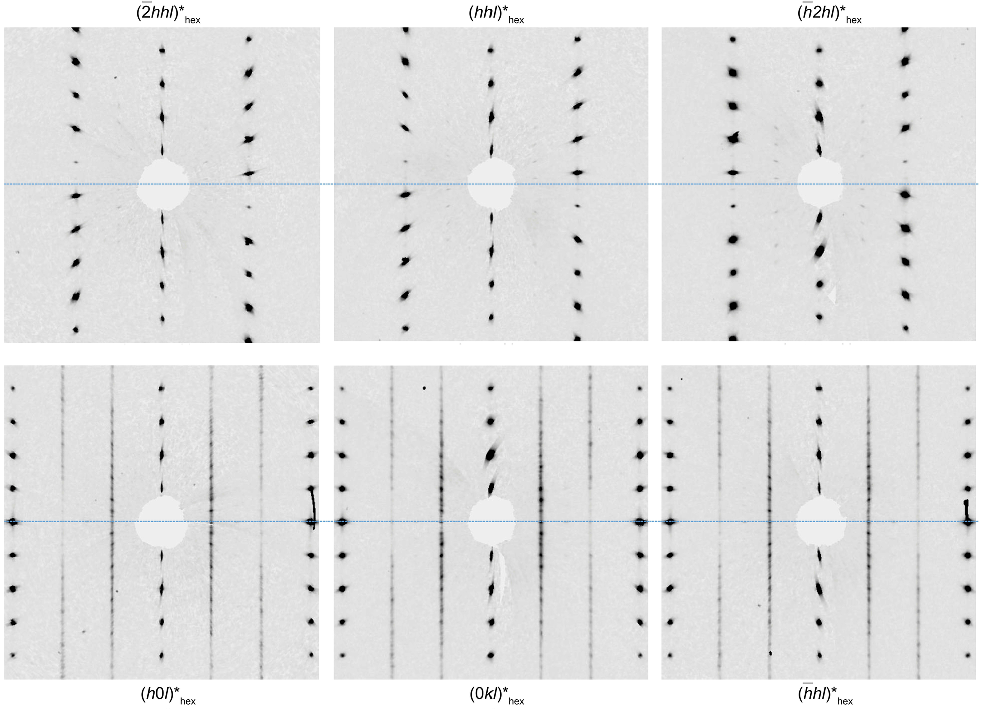
 (Fig. 14), but the diffuse streaks, and the additional presence of another polytype hampered the unambiguous interpretation of diffraction patterns. This allotwin is rare, and it has only been identified initially in the extraterrestrial cronstedtite of the Paris meteorite (Pignatelli et al., Reference Pignatelli, Mugnaioli and Marrocchi2018) and later in terrestrial cronstedtites from Morocco (Hybler et al., Reference Hybler, Dolníček, Sejkora and Števko2021b).
Reciprocal sections of a 3T + 2M 1 allotwin. Stronger reflections are those of the 3T polytype; the 2M 1 polytype shows weak reflections and diffuse streaks.

Figure 14. Long description
Top row, from left to right: The first panel labeled (-2hhl)*hex shows strong, sharp spots aligned along vertical and diagonal axes, with a central masked region. The second panel, (hhl)*hex, displays a similar pattern but with slightly different spot spacing and orientation. The third panel, (-h2hl)*hex, shows weaker spots and more pronounced diffuse streaks, especially along the vertical direction. Bottom row, from left to right: The fourth panel, (h0l)*hex, features vertical columns of spots with some streaking and a central masked area. The fifth panel, (0kl)*hex, presents vertical lines of spots with diffuse intensity and a central mask. The sixth panel, (-hhl)*hex, shows vertical spot columns with diffuse streaks and a masked center. Across all panels, the strongest reflections correspond to the 3 T polytype, while weaker reflections and diffuse streaks indicate the presence of the 2 M 1 polytype.
2M
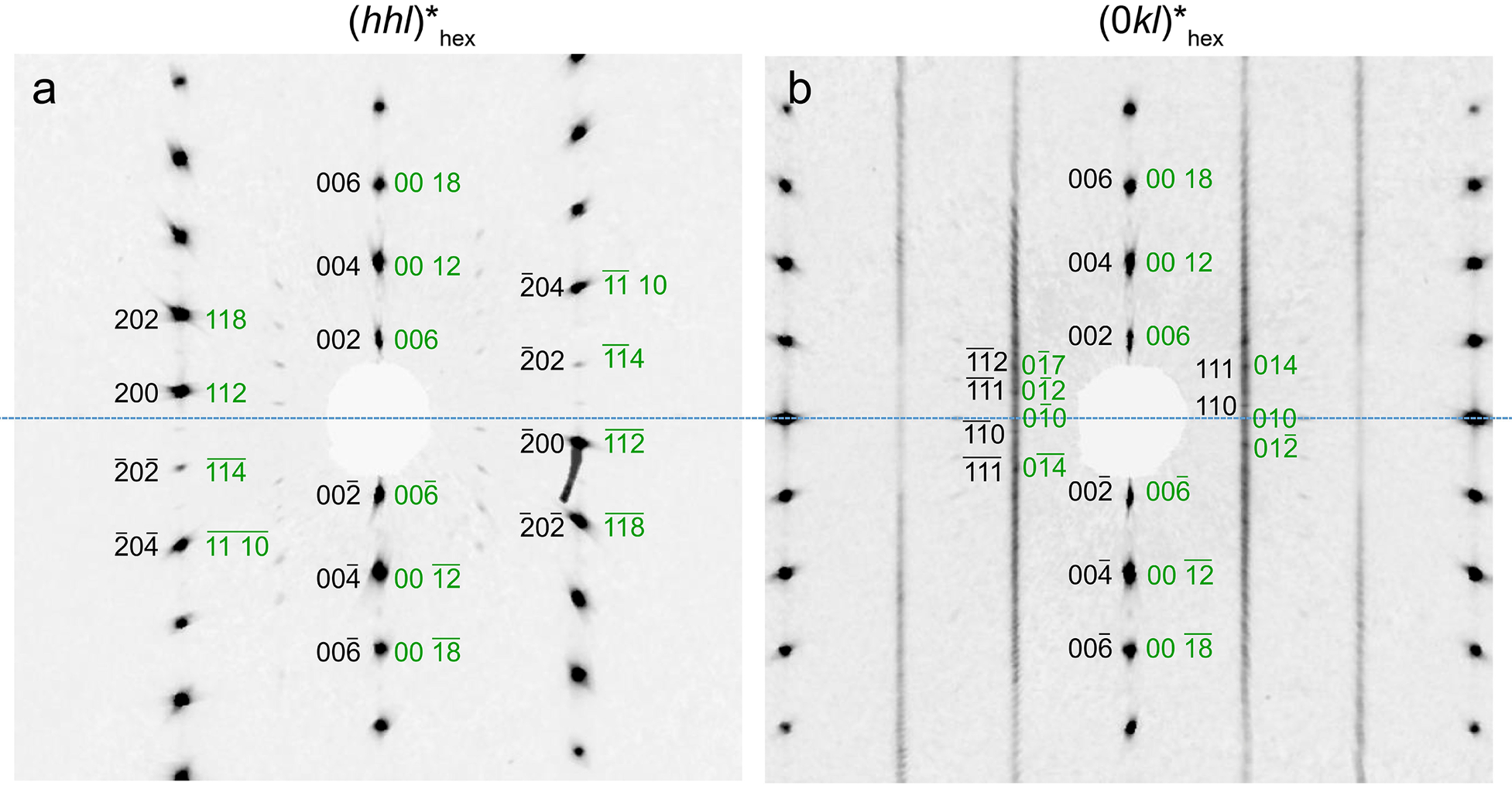
1 forms another allotwin with the 6T
2 polytype, which also belongs to subfamily A (Fig. 15). Like the 3T polytype, the intensities of reflections along
$ {[10l]}^{\ast }/{[01l]}^{\ast }/{[\overline{1}1l]}_{\hskip3pt \mathrm{h}\mathrm{e}\mathrm{x}}^{\ast } $
 decrease with increasing ǀlǀ in 6T
2, but some of them can become stronger due to the coexistence with 2M
1 (Hybler et al., Reference Hybler2016). Stacking disorder, in addition to weak reflections indicating the probable presence of twinning, make the identification of 6T
2 uncertain. The unit-cell parameters of both 6T
2 and 2M
1 were found automatically by the indexing procedure during the X-ray data treatment for different portions of the same crystal (Table S2, Supplementary material). Twinning concerns 2M
1 with 180° rotation along the [001]* axis. This is the so-called ‘obverse-reverse’ twin described by Ferraris et al. (Reference Ferraris, Makovicky and Merlino2008), which can affect all polytypes of subfamily A, and was reported for the first time in cronstedtite by Hybler et al. (Reference Hybler2016).
Reciprocal sections of a 2M 1 + 6T 2 allotwin. (a) (hhl)*hex shows the occurrence of both polytypes belonging to subfamily A (black indices correspond to reflections of 2M 1, and green indices are those of 6T 2). (b) Stronger reflections along [01l]*hex on (0kl)*hex belong to both polytypes, and the remaining reflections are those of 6T 2.

Figure 15. Long description
The left panel, labeled a, displays (hhl)*hex. Black indices such as 006, 004, 002, 202, 200, -2 0 -2 , and -2 0 -4 correspond to 2 M 1 reflections, while green indices like 00 18, 00 12, 00 6, 118, 112, -1-14, and -1-1 10 are for 6 T 2. Indices are symmetrically arranged around the central blank region, radiating outward along six principal directions. The right panel, labeled b, shows (0kl)*hex. Stronger reflections are aligned vertically along the [01l]*hex, with black indices 006, 004, 002, 112, 111, 110, and their negatives, and green indices 00 18, 00 12, 00 6, 0-17, 0-12, 010, 014, and 0-1-4. The green indices are interspersed among the black, with some unique to 6 T 2. Both panels have a central blank circle, and the reflection spots are distributed symmetrically about the horizontal axis.
The 2M 1 polytype has not been found as an isolated crystal in Salsigne samples. This polytype is rare in natural samples and has been detected only in cronstedtite from Morocco (Hybler et al., Reference Hybler, Dolníček, Sejkora and Števko2021b). However, it was also documented in the products of syntheses (Hybler et al., Reference Hybler, Klementová, Jarošová, Pignatelli, Mosser-Ruck and Ďurovič2018; Pignatelli et al., Reference Pignatelli, Mugnaioli, Mosser-Ruck, Abdelmoula and Sterpenich2024).
Allotwins occur because all polytypes have the same structure at the surface of the (001) plane so that juxtaposing two polytypes having this plane as their interface creates no structural discontinuity. Three mechanisms can be considered for the formation of allotwins, all of which are closely related to the origin of twins:
-
(1) A perturbation of the spiral growth of a polytype, leading to a modification of the layer stacking sequence, similar to the perturbative mechanism proposed for the origin of long-period mica polytypes (Nespolo, Reference Nespolo2001). The stacking sequence resulting from the perturbation is different from that in the initial crystal, creating an allotwin.
-
(2) Oriented attachment (Nespolo and Ferraris, Reference Nespolo and Ferraris2004b) of crystals of different polytypes, which requires the presence of a fluid phase; the abundance of different polytypes in the Salsigne cronstedtite suggests that this mechanism, commonly known as synneusis in the petrological community (Vogt, Reference Vogt1921; Vance, Reference Vance1969), could have been active.
-
(3) The action of an oriented pressure on the crystal, which may have resulted in the gliding or change of orientation of a portion of the crystal with respect to another portion.
Conclusions
This work represents another missing piece of the cronstedtite puzzle. Our results described for the first time the chemical and structural features of crystals from the Salsigne mine. Several kinds of allotwin have been identified in this study (3T + 1M, 3T + 2M 1, 3T + 6T 2, and 2M 1 + 6T 2). The Salsigne cronstedtite differs from those from all other localities in terms of its tetrahedral iron content, which is greater, as well as by the fact that its polytypes belong almost exclusively to subfamily A (1M, 3T). These two features could be related to crystallization conditions, but the relationship between physical/chemical parameters (T, pH, etc.), the formation of cronstedtite and its chemical/structural features has not been established. Recent work emphasized the apparent effect of temperature on the stacking sequence, i.e. the polytype (Hybler et al., Reference Hybler, Klementová, Jarošová, Pignatelli, Mosser-Ruck and Ďurovič2018), as well as the effect of liquid/rock ratio and the Si source (Pignatelli et al., Reference Pignatelli, Mosser-Ruck, Mugnaioli, Sterpenich and Gemmi2020; Pignatelli et al., Reference Pignatelli, Mugnaioli, Mosser-Ruck, Abdelmoula and Sterpenich2024), but much work remains to be done to understand how cronstedtite forms in terrestrial environments.
Supplementary material
The supplementary material for this article can be found at http://doi.org/10.1017/cmn.2026.10032.
Author contribution
I. Pignatelli: Writing – review, editing, investigation, conceptualization. M. Nespolo: writing, review. J. Hybler: investigation and data treatment. M. Abdelmoula: investigation, review, editing. C. Lheur: providing samples, review.
Acknowledgments
The authors thank Dr Chantal Pfeiffer for the LA-ICP-MS analyses, Mr Alexandre Flammang for help with sample preparation, and Dr Marc Ulrich for μ-XRF data acquisition. This is CRPG contribution #2876.
Competing interests
The authors declare none.