

Introduction
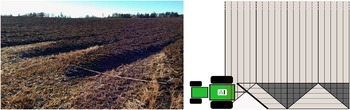
When cultivating crops, soil and seedbed quality is crucial for crop establishment and can have direct impact on the yield (Braunack and Dexter, Reference Braunack and Dexter1989; Guérif et al., Reference Guérif, Richard, Dürr, Machet, Recous and Roger-Estrade2001; Håkansson et al., Reference Håkansson, Arvidsson, Keller and Rydberg2011). The primary seedbed tillage operation is crucial for a homogeneous development of a crop and requires an adequate and uniform ploughing operation across the entire field. This is especially challenging to achieve at the interface between the headland and the main working area of the field. This occurs both when the plough is elevated and lowered in the headland, forming an inconsistent tillage operation and undesirable triangular shapes of unploughed segments (Fig. 1, left). This leads to overlapping operations when ploughing the headland perpendicularly to the main working direction (Fig. 1, right), which also is time- and energy- consuming and increases wear of the plough. Poor soil inversion is typically seen in interface areas with overlap, which may cause problems with seeding as well as pest and weed control. This is especially of concern in organic farming when large ploughs are used, because chemical weed and pest control not is an option.
Triangular segments of unploughed soil (left) and a theoretical concept drawing for conventional ploughing (right)

Soil compaction has been studied in relation to machine traffic and tillage practices (Hamza and Anderson, Reference Hamza and Anderson2005; Shamal et al., Reference Shamal, Alhwaimel and Mouazen2016). Other studies have analysed the effect and impact on the tillage quality and energy consumption of different soil types, water contents and wear (sharpness and thickness) of the cutting edge (Natsis et al., Reference Natsis, Papadakis and Pitsilis1999; Vilde, Reference Vilde2008). Site-specific tillage effects on energy consumption have been quantified in a number of studies (Abbaspour-Gilandeh et al., Reference Abbaspour-Gilandeh, Khalilian, Alimardani, Keyhani and Sadati2005; Bertocco et al., Reference Bertocco, Basso, Sartori and Martin2008; Keskin et al., Reference Keskin, Khalilian, Han and Dodd2011; Raper et al., Reference Raper, Reeves, Shaw, van Santen and Mask2005) and a range of studies have measured and predicted draught forces for mouldboard ploughing from different soil parameters, plough geometries, forward speed and operation depth (Godwin et al., Reference Godwin, O’Dogherty, Saunders and Balafoutis2007; Kuczewski, Reference Kuczewski1981; Mari et al., Reference Mari, Ji, Chandio, Arslan, Sattar and Ahmad2015; Qiong et al., Reference Qiong, Pitt and Ruina1986). To our knowledge, there have been no studies on section control of a mouldboard plough and on tested the operational effect. Section control is well known in other agricultural operations such as spraying (Luck et al., Reference Luck, Zandonadi, Luck and Shearer2010), and therefore the GNSS technology and high-level control will not be presented in this study.
By introducing section control on the plough, each plough section can be independently controlled for elevating and lowering into the soil. The hypothesis was that with independent section control, the undesirable triangular segments at the interface between the headlands and the main working area will be nearly eliminated, i.e. starting the ploughing operation in an approximately straight line, perpendicular to the main working area of the field. Different concepts were described, modelled and the selected ‘optimal’ solution was implemented on a real concept plough. The aim of the research was to investigate, describe and perform a proof-of-concept of a novel innovative plough concept design with individual section control, to significantly optimise ploughing operation in the interface area between the headland and the main working area.
Experimental method for draught forces determination
Initial field experiments were carried out to determine the draught forces used in the ploughing operation. These results were used for dimensioning the section control system. The first step was to describe and compare different concepts of section control, using a modelling tool. In the second step, the selected ‘best’ concept was constructed and implemented on a real plough, for additional evaluation. The concept plough was a five-furrow Agrolux MRWS-P with shear bolts, fully-mounted reversible from Kongskilde Industries A/S, DK.
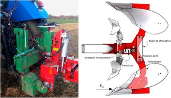
The accumulated draught force was determined in the initial field experiment before starting analysing different hypothetical concepts. The ploughed soil texture consisted of 3.7% organic matter, 9.6% clay, 22.3% silt, and 64.5% sand, with at 25 kg 100 kg−1 gravimetric water content. The experiment was carried out with force transducers (strain-gauges) mounted in the tractor lift (three point linkage), measuring the horizontal draught forces (Fig. 2, left). The soil was ploughed to 0.25 m depth at 8 km h−1 and a furrow width of 0.4 m. This corresponds to a soil volume flow of 0.22 m3 s−1 for each furrow.
Experimental lift frame with horizontal force transducers to determine the common draught force (left), and the modification of the plough section shear bolt for implementation of the one section force transducer (right).

An even distribution of the horizontal forces between each furrow was assumed and the equilibrium equation could therefore be established (Eq. 1):
 $$F_{x} {\,\equals\,}F_{{vx}} {\plus}F_{{hx}} {\plus}F_{{tx}} {\plus}5F_{{fx}} {\plus}F_{{lx}} {\,\equals\,}0$$
where F x is the sum of the horizontal forces, F vx is the left lift arm,F hx is the right lift arm, F tx is the top linkage, F fx is the furrow counter draught force, F lx is the plough wheel counter draught friction force for rolling. When neglecting the inconsiderable rear wheel draught force of the plough, Eq.1 can be rewritten as Eq. 2:
 $$F_{{lx}} \approx0 \mathop{-\!-\!\!\!\to}\limits^{{yields}} F_{{fx}} {\,\equals\,}{{F_{{vx}} {\plus}F_{{hx}} {\plus}F_{{tx}} } \over 5}$$
The accumulated horizontal furrow draught forces (F vx +F hx +F tx ) were measured to approx. 32 kN in the experiment. Therefore, each section draught force F fx was estimated to 6.4 kN.
To determine the resulting force position, an additional experiment was conducted where a force transducer was used, replacing the of the shear bolt (Fig. 2, right). With this experimental setup it was possible to measure the moment around the beam rotation point. By combining the measured moment in the furrow beam with the determined horizontal force F fx , the resulting horizontal force point of attack was found by equilibrium calculations.
The point of attack for the force F fx was calculated to be 0.67 m below the surface of the common plough frame (Fig. 2, right). The calculated position combined with the draught force measurement was used for dimensioning the hydraulic system and the mechanical construction of the concept plough model.
Concept investigation
System requirements
In general, the concept must not interfere with conventional ploughing performance and it must match its original operational ability. The developed concept system must be able to resist the counter forces without permanent deformation of the construction and withstand the rough environmental impacts. The plough section must be able to elevate the section above the soil surface, corresponding to 0.30 m, when the plough frame is lowered. The sections should operate with an elevation velocity that ensures rapid activation and deactivation of the modified section. Due to the great force and velocity demands, a hydraulic supply from the tractor was required. The concepts were designed to be implementable on most existing low-cost reversible ploughs. Therefore, the simple five-furrow reversible plough with shear bolts was chosen.
Considered concepts
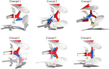
The functionalities and material stress of the considered section control concepts were analysed using SolidWorks (Dassault Systèmes SolidWorks Corp, USA). The six considered concepts are illustrated in Fig. 3.
Considered ploughing concepts for the section control, analysed by modelling. The blue colour indicates the crucial dynamic parts of the concepts modifications and the red indicate the conventional frame and beam of the plough.

Concept 1
Concept 1 removed the shear bolt and used the existing bolted connection as a hinge to rotate the body. This concept model showed that the body was not able to rotate above the soil surface. A similar solution was tested by using the original shear bolt as a rotation hinge. This solution would not work because the rotated mouldboard interfered with the above mouldboard. Therefore, this solution was considered unusable.
Concept 2
In concept 2 an attempt was made to model a solution where a parallelogram raised and lowered the entire section. This solution ensured that the body kept its original operational angle regarding to the beam position of the plough. In addition, it would be possible to control the depth of the individual furrows. The parallelogram mechanism had to be able to elevate the body of the plough above the soil surface, resulting in an unsteady construction. To withstand the forces of the soil acting on the body, the steel material had to be particularly strong. Furthermore, the geometry of the parallelogram required a specially crafted double-acting telescopic hydraulic cylinder, which was less robust and more expensive. Therefore, this concept was rejected, although it had considerable potential for controlling the operation depth of the sections.
Concept 3
Rotation of the entire section was considered in concept 3. This concept used one double-acting hydraulic cylinder, which was able to control the section in both directions. In order to rotate/elevate the body above the soil surface, the bracket of the section had to be extended. This concept was robust and met all the requirements for the concept model.
Concept 4
This concept used a milled track to be able to rotate and traverse the body to achieve the required elevation height without interfering with the above mouldboard. The mechanism was not robust and after wearing it could potentially lead to an unstable arrangement. In addition, using milled tracks was not considered as preferred methods, due to the large operational forces.
Concept 5
Concept 5 was a model with a linear rail moving the section. This solution had the same benefit as in concept 2, regarding depth control. The linear rail needed to be at least 0.6 m to be able to lower and elevate the bodies in both directions, above the surface. With this large length of stroke, the linear rail took up too much of the clearance height between the beam and the soil. Moreover, the linear mechanism was also vulnerable to the rough environment and the large operational forces.
Concept 6
Concept 6 used a model with a linear movement of the body, similar to concept 5. In this model, each body was able to be controlled individually. The rail replaced the body and beam, but it also took up too much of the clearance height. This required a travel length of 0.3 m which caused the bodies to interfere with each other unless the entire plough was reconstructed. Similar to concept 5, the linear mechanism was not robust.
Description of the selected concept
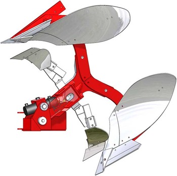
Concept No. 3 was chosen as the ‘best’ concept to control the individual sections (Fig. 4). With this concept only one conventional hydraulic cylinder was required per section to control the rotating mechanism. The hydraulic cylinder and the rotating mechanism formed a robust construction where maintenance is restricted to grease lubrication. Material construction was optimised regarding deflection and deformation by using the finite element method (FEM) based on the forces, determined in the initial experiments.
Final model of the chosen concept for controlling the individual sections, consisting of the rotational construction of the section, controlled by the hydraulic cylinder.

Instrumentation hardware
For positioning the section, a linear displacement sensor, TX2, was implemented (Novotechnik, U.S.) operating with a resolution of 0.01 mm and linearity of up to 0.05%, and protected against the environment (IP67). For real-time data processing, a B&RX20 controller with a 12-bit A/D converter was used (B&R Industrial Automation, AUT). For global positioning the GNSS unit BT-Q1000XT was used (Qstarz, TWN).
Hydraulic system
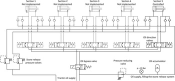
The full-scale hydraulic system for controlling all sections is shown in Fig. 5. Only one section was used for the physical modification used in the proof-of-concept plough. The cylinder was double-acting for elevating and lowering the section (Dcyl=80 mm & Dpis=40 mm). For section control, a 4/3 directional oil control valve was implemented with a closed centre, which was electrically controlled by two solenoids. To generate the system generic, a bypass valve was implemented allowing unhampered oil circulation. A new hydraulic stone release system was introduced, controllable by stone release pressure valves (Fig. 5). The pressure valves were set to be activated when a force of approx. 7 kN acts on the body. The horizontal length of stroke was 0.48 m, and when ploughing at 8 km h−1 the section should be able to travel the entire length of stroke within 120 ms. This rapid operation induces an oil flow of 134 l min−1, which should be led through the stone release pressure valves. To avoid cavitation in the cylinder, the system was supplied with oil, by using a low-pressure refilling system (Fig. 5). For additional cost optimisation, the cavitation refilling system all one-way valves and the stone release pressure valves can be removed.
Full-scale hydraulic diagram. The dotted lines indicate the additional four sections that not were modified on the concept plough.

Theoretical validation of the concept
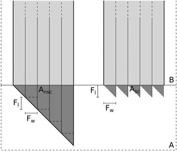
When introducing the concept on the full-scale plough, the interface area (A) between the headland and the main working area (B) will theoretically be significantly reduced, as shown in Fig. 6 left (conventional) and right (new concept).
Conventional ploughing (left) and ploughing with section control (right)

The overlapping area can be calculated with section control, A sc (Eq. 4), and without section control, A nsc , (Eq. 3):
 $$A_{{nsc}} {\,\equals\,}{{F_{l} n^{2} F_{w} } \over 2}$$
 $$A_{{sc}} {\,\equals\,}{{F_{l} nF_{w} } \over 2}$$
where F w is the width of one furrow, n is the number of furrows and F l is the length of each furrow. The percentage of the reduced overlapping area with section control, P saved , can be calculated (Eq. 5):
 $$P_{{saved}} {\,\equals\,}\left( {1{\minus}{{A_{{sc}} } \over {A_{{nsc}} }}} \right)100$$
This means that theoretically, the overlapping area for a five-furrow plough will be reduced by 80%, increasing with the number of furrows. Additional benefits will occur when ploughing irregularly shaped fields.
Visual field validation of the concept plough
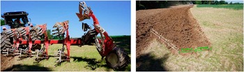
The concept model was implemented on the conventional reversible plough by modifying the section (Fig. 7, left). The concept plough was used to validate the modelled concept on a real physical plough. Furthermore, it allowed demonstration of the concept to illustrate the impact on the soil surface from a real ploughing operation.
Concept plough with one section modified (left) and operational result from the concept plough (right)

The concept optimised the operation towards a homogeneous soil reversal at the interface, demonstrated in the final field experiment (Fig. 7, right). Furrow 1 to furrow 4 clearly showed the addressed interface problem. When activating the concept, implemented on section 5, the ploughing operation started nearly perpendicular to the main working area, as it can be seen by a visual surface inspection (Fig. 7, right).
Conclusion
Six plough section control concepts were evaluated by modelling, and the selected ‘best’ functional concept was constructed and implemented on a conventional five-furrow plough. In addition, a new hydraulically adjustable stone release system was integrated. The modified plough with the novel concept showed great performance in controlling the individual section when demonstrated in a real field operation. A more homogeneous soil reversal and less random soil mixing can therefore be expected in the interface area between headlands and cropping areas. Another benefit of the system is that irregularly shaped fields can be ploughed at a constant furrow width, by activate or deactivate the individual sections, in the operation.
Acknowledgements
The project was funded by Innovation Fund Denmark through ‘Future Cropping’.