Introduction
The physics of modern functional materials is governed by nanoscale heterogeneity and processes occurring on fast to ultrafast time scales. Observations with high spatial and temporal resolution allow for a comprehensive understanding of microscopic couplings and correlations, ultimately facilitating active control of properties, excitations, and transformations. Ultrafast metrology, including time-resolved optical and photoelectron spectroscopy,Reference Bovensiepen, Petek and Wolf1 electron and x-ray diffraction,Reference Miller2–Reference Lindenberg, Larsson, Sokolowski-Tinten, Gaffney, Blome, Synnergren, Sheppard, Caleman, MacPhee, Weinstein, Lowney, Allison, Matthews, Falcone, Cavalieri, Fritz, Lee, Bucksbaum, Reis, Rudati, Fuoss, Kao, Siddons, Pahl, Als-Nielsen, Duesterer, Ischebeck, Schlarb, Schulte-Schrepping, Tschentscher, Schneider, von der Linde, Hignette, Sette, Chapman, Lee, Hansen, Techert, Wark, Bergh, Huldt, van der Spoel, Timneanu, Hajdu, Akre, Bong, Krejcik, Arthur, Brennan, Luening and Hastings4 and spectroscopy, yields access to multiple degrees of freedom down to the femtosecond and attosecond range.
Structural dynamics in strongly heterogeneous systems, such as nanostructures, surfaces, and monolayers, are of particular interest, but also pose great experimental challenges. In recent years, various techniques for ultrafast nanoscale probing were established, enabling, for example, time-resolved scanning near-field optical microscopyReference Huber, Plankl, Eisele, Marvel, Sandner, Korn, Schüller, Haglund, Huber and Cocker5–Reference Wagner, Fei, McLeod, Rodin, Bao, Iwinski, Zhao, Goldflam, Liu, Dominguez, Thiemens, Fogler, Castro Neto, Lau, Amarie, Keilmann and Basov7 and scanning tunneling microscopy,Reference Terada, Yoshida, Takeuchi and Shigekawa8–Reference Cocker, Peller, Yu, Repp and Huber10 electron point-projection microscopy,Reference Quinonez, Handali and Barwick11–Reference Vogelsang, Robin, Nagy, Dombi, Rosenkranz, Schiek, Groß and Lienau13 and lensless imaging using extreme ultraviolet radiation.Reference Gaffney and Chapman14–Reference Kfir, Zayko, Nolte, Sivis, Möller, Hebler, Arekapudi, Steil, Schäfer, Albrecht, Cohen, Mathias and Ropers16
Ultrashort electron pulses are ideally suited probes of materials structure and dynamics down to the atomic scale.Reference Miller17,Reference Zewail18 Ultrafast diffraction in transmission,Reference Zewail3,Reference Miller17,Reference Musumeci, Moody, Scoby, Gutierrez, Bender and Wilcox19–Reference Manz, Casandruc, Zhang, Zhong, Loch, Marx, Hasegawa, Liu, Bayesteh, Delsim-Hashemi, Hoffmann, Felber, Hachmann, Mayet, Hirscht, Keskin, Hada, Epp, Flöttmann and Miller23 grazing incidence,Reference Liang, Schäfer and Zewail24–Reference Frigge, Hafke, Witte, Krenzer, Streubühr, Samad Syed, Mikšić Trontl, Avigo, Zhou, Ligges, von der Linde, Bovensiepen, Horn-von Hoegen, Wippermann, Lücke, Sanna, Gerstmann and Schmidt26 and backscatteringReference Vogelgesang, Storeck, Horstmann, Diekmann, Sivis, Schramm, Rossnagel, Schäfer and Ropers27 geometries is now established. Nanoscale real-space imaging, on the other hand, is possible using ultrafast transmissionReference Zewail18,Reference Dömer and Bostanjoglo28,Reference Kim, LaGrange, Reed, Taheri, Armstrong, King, Browning and Campbell29 and scanningReference Yang, Mohammed and Zewail30,Reference Sun, Melnikov, Khan and Mohammed31 electron microscopy. These techniques are rapidly expanding in scope, driven by strong developments of high-brightness pulsed electron sources.Reference Weathersby, Brown, Centurion, Chase, Coffee, Corbett, Eichner, Frisch, Fry, Gühr, Hartmann, Hast, Hettel, Jobe, Jongewaard, Lewandowski, Li, Lindenberg, Makasyuk, May, McCormick, Nguyen, Reid, Shen, Sokolowski-Tinten, Vecchione, Vetter, Wu, Yang, Dürr and Wang22,Reference Van Oudheusden, De Jong, van der Geer, Op ’t Root, Luiten and Siwick32–Reference Daoud, Floettmann and Miller37
In this article, we discuss two complementary schemes to access ultrafast structural dynamics using high-coherence electron pulses from localized photoelectron sources. Specifically, ultrafast low-energy electron diffraction (ULEED) probes the orientation, symmetry, and long-range order of materials with ultimate surface sensitivity, while ultrafast transmission electron microscopy (UTEM) translates atomic-scale imaging and local diffraction to the ultrafast domain. We will introduce these methods and discuss selected examples of laser-induced structural dynamics probed by them.
Electron pulses from nanoscale sources
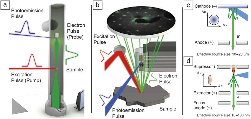
Ultrafast electron diffraction and microscopy use a stroboscopic approach, following the principle of optical pump-probe techniques, as illustrated in Figure 1a–b. An ultrashort laser pulse (red) excites a transmission electron microscope specimen or surface, and the structural response is probed by a delayed electron pulse (green) in transmission or backreflection. By repetitive sampling at varying delays, a time-dependent “movie” of the induced dynamical process can be composed. The real-space and reciprocal space resolution of these techniques crucially depend on the quality of the employed electron beam.Reference Reiser38 As a figure of merit, the brightness B ∼ I/(εx ⋅ εy) is proportional to the beam current I per occupied transverse phase space area, quantified by the beam emittances εx,y.Reference Reiser38 Electron pulses are typically generated by laser-induced photoemission, and the intrinsic source emittance can thus be reduced by optimizing the photocathode work function and materialReference Dowell and Schmerge39,Reference Kuwahara, Nambo, Aoki, Sameshima, Jin, Ujihara, Asano, Saitoh, Takeda and Tanaka40 and by tailoring the wavelengthReference Kasmi, Kreier, Bradler, Riedle and Baum41 or focusing conditions.Reference Gerbig, Senftleben, Morgenstern, Sarpe and Baumert35,Reference Merano, Collin, Renucci, Gatri, Sonderegger, Crottini, Ganière and Deveaud42 Following a different path, our laboratory and other groups are actively pursuing ultrafast laser-triggered electron emission from nanoscale tip-shaped photocathodes,Reference Ropers, Solli, Schulz, Lienau and Elsaesser43–Reference Herink, Solli, Gulde and Ropers47 yielding high-coherence electron pulsesReference Ehberger, Hammer, Eisele, Krüger, Noe, Högele and Hommelhoff48–Reference Houdellier, Caruso, Weber, Kociak and Arbouet50 in tunable electrostatic emitter geometries.Reference Gulde, Schweda, Storeck, Maiti, Yu, Wodtke, Schafer and Ropers21,Reference Feist, Bach, Rubiano da Silva, Danz, Möller, Priebe, Domröse, Gatzmann, Rost, Schauss, Strauch, Bormann, Sivis, Schäfer and Ropers49,Reference Paarmann, Gulde, Müller, Schäfer, Schweda, Maiti, Xu, Hohage, Schenk, Ropers and Ernstorfer51–Reference Schröder, Sivis, Bormann, Schäfer and Ropers53
Ultrafast electron microscopy and diffraction using laser-triggered field emitters. Optically induced dynamics are probed (a) in transmission by ultrafast transmission electron microscopy (electron kinetic energy: 120–200 keV) and (b) at surfaces by ultrafast low-energy electron diffraction (electron kinetic energy: 10–500 V), employing low-emittance ultrashort electron pulses. (c–d) Conceptual design of ultrafast photoemission electron sources. (c) In a planar photocathode geometry, electrons are emitted from micrometer-sized areas (governed by typical laser focal spot diameters of 10–20 µm), while (d) the laser-triggered field emitter localizes electron emission to the nanoscale apex of a sharp metal tip (typical diameter of 10–100 nm), facilitating high-coherence electron pulses. Top-left corner: Illustration of occupied transverse phase space for the respective emitter geometry.Reference Feist, Bach, Rubiano da Silva, Danz, Möller, Priebe, Domröse, Gatzmann, Rost, Schauss, Strauch, Bormann, Sivis, Schäfer and Ropers49,Reference Storeck, Vogelgesang, Sivis, Schäfer and Ropers57 Note: Δα, transverse angular beam spread; Δx, transverse spatial beam spread.

The low intrinsic source emittance and large degree of coherence provided by nanoscale photoemitters (Figure 1c–d) allows for highly collimated and tightly focused pulsed electron beams, which is instrumental to the two experimental approaches described next, ULEED and UTEM.
ULEED
We first present a novel approach to track ultrafast structural dynamics at surfaces and monolayer films. This work is motivated by the particular importance of low-dimensional systems, many of which exhibit unique electronic, structural, and magnetic phases and excitations. Spontaneous symmetry breaking and various topological states are hallmarks of surface systems,Reference Hasan and Kane54 and both their optical control and ultrafast dynamics are an exciting field of study. Today, detailed snapshots of the evolution of electronic excitations at surfaces can be recorded by angle-resolved photoelectron emission spectroscopy.Reference Bovensiepen, Petek and Wolf1 In contrast, until recently, ultrafast access to the associated structural degrees of freedom has been more restricted.
Electron beams represent an ideal probe of surface structure by backscattering diffraction. In particular, diffraction with surface sensitivity to the first few monolayers is obtained at very low normal momentum. In reflection high-energy electron diffraction,Reference Ichimiya and Cohen55 this is achieved by employing a grazing incidence geometry, and several ultrafast implementations of this technique have been successful.Reference Liang, Schäfer and Zewail24,Reference Hanisch-Blicharski, Janzen, Krenzer, Wall, Klasing, Kalus, Frigge, Kammler and Horn-von Hoegen25 However, as a more widely used method in surface science, low-energy electron diffraction (LEED) at normal incidence is arguably the preferred choice for obtaining quantitative information on the symmetry and long-range order of a surface.Reference Van Hove, Weinberg and Chan56 We have therefore undertaken the development of ULEED, which has resulted in the first observations of ultrafast structural transitions in transmissionReference Gulde, Schweda, Storeck, Maiti, Yu, Wodtke, Schafer and Ropers21 and backscattering diffraction at low electron-beam energies.Reference Vogelgesang, Storeck, Horstmann, Diekmann, Sivis, Schramm, Rossnagel, Schäfer and Ropers27,Reference Storeck, Vogelgesang, Sivis, Schäfer and Ropers57
The challenge in implementing ULEED lies in the need for ultrashort (picosecond or femtosecond) electron pulses at low energies. At the corresponding slow electron propagation speeds, an initially short electron pulse with some energy spread is substantially broadened until it reaches a sample. By minimizing the propagation distance from the photoelectron source to the sample, we realized an ultrafast LEED setup in a transmission geometry to study the dynamics of a polymer layer on freestanding graphene.Reference Gulde, Schweda, Storeck, Maiti, Yu, Wodtke, Schafer and Ropers21
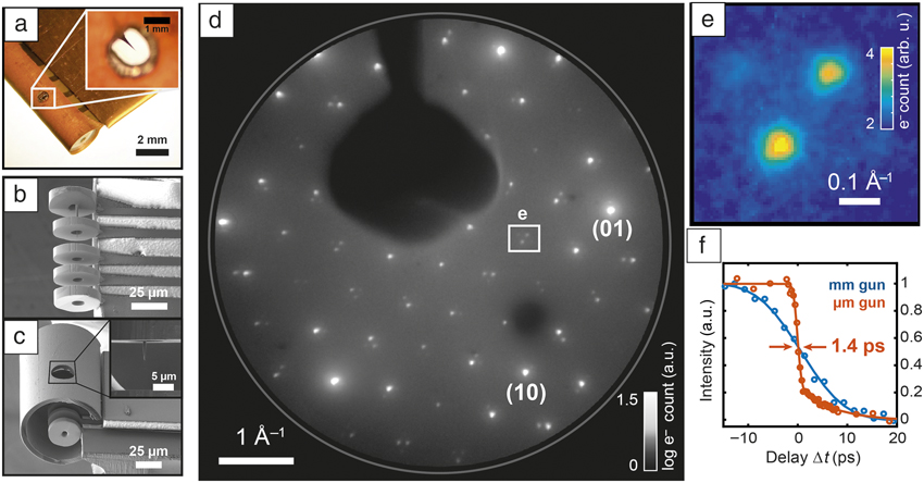
For the more generic case of backscattering, shorter source–sample distances require drastic downscaling of the electron gun to avoid shadowing. We addressed this issue by implementing two types of compact photoelectron guns with diameters in the millimeter (Figure 2a) and micrometer (Figure 2b–c) ranges, respectively. Both geometries consist of an electrostatic lens assembly hosting a laser-driven nanotip electron source. Specifically, the micrometer-scale electron gun (Figure 2b–c) is fabricated by optical lithography and focused ion beam etching.Reference Storeck, Vogelgesang, Sivis, Schäfer and Ropers57 An exemplary diffraction pattern and the temporal resolution of presently 1.4 ps27 are shown in Figure 2d–f. Notably, the high beam coherence facilitated by the localized electron source allows for sharp diffraction spots (Figure 2e). Here, higher-order satellite diffraction spots from a periodic lattice distortion in 1T-TaS2,Reference Spijkerman, de Boer, Meetsma, Wiegers and van Smaalen58 where 1T refers to the single-layer trigonal polytype, are clearly resolved. The combination of high momentum and high temporal resolution with ultimate surface sensitivity makes ULEED a versatile approach to study structural dynamics and ordering phenomena at surfaces, as illustrated in the following.
Laser-driven electron guns for ultrafast low-energy electron diffraction (ULEED). (a) Millimeter-scale electrostatic lens assembly with a nanotip field emitter (optical microscope image). Inset: Close-up of nanotip. (b) Micrometer-scale electron gun, featuring Schottky-type extractor-suppressor unit and collimation einzel lens (scanning electron micrograph). (c) Electron gun covered by a ground shield with a hole for laser excitation. Inset: Nanotip photocathode. (d) ULEED diffraction pattern from a 1T-TaS2 surface recorded with photoelectrons (room temperature, 100 eV energy, millimeter-scale gun), showing lattice Bragg peaks (some labeled) and satellite peaks from a periodic lattice distortion. (e) Zoom-in of region denoted in (d), resolving adjacent higher-order satellite peaks. (f) Temporal resolution of electron guns measured by laser-induced change in diffraction intensity. A temporal resolution down to 1.4 ps is reached.Reference Vogelgesang, Storeck, Horstmann, Diekmann, Sivis, Schramm, Rossnagel, Schäfer and Ropers27,Reference Storeck, Vogelgesang, Sivis, Schäfer and Ropers57

Phase ordering of charge-density waves resolved by ULEED
We recently employed ULEED to investigate optically induced structural phase transitions and the emergence of long-range order following an ultrafast quench.Reference Vogelgesang, Storeck, Horstmann, Diekmann, Sivis, Schramm, Rossnagel, Schäfer and Ropers27 Specifically, here, we address the transition between two charge-density wave (CDW) phases of 1T-TaS2, a layered transition-metal dichalcogenide. This material is an intensely studied model system displaying various CDW phasesReference Rossnagel59 and metastable states,Reference Stojchevska, Vaskivskyi, Mertelj, Kusar, Svetin, Brazovskii and Mihailovic60 the transitions between which were observed by time-resolved photoemission spectroscopy,Reference Perfetti, Loukakos, Lisowski, Bovensiepen, Berger, Biermann, Cornaglia, Georges and Wolf61–Reference Ligges, Avigo, Golež, Strand, Beyazit, Hanff, Diekmann, Stojchevska, Kalläne, Zhou, Rossnagel, Eckstein, Werner and Bovensiepen64 electron diffraction,Reference Eichberger, Schäfer, Krumova, Beyer, Demsar, Berger, Moriena, Sciaini and Miller65,Reference Haupt, Eichberger, Erasmus, Rohwer, Demsar, Rossnagel and Schwoerer66 and x-ray diffraction.Reference Laulhé, Huber, Lantz, Ferrer, Mariager, Grübel, Rittmann, Johnson, Esposito, Lübcke, Huber, Kubli, Savoini, Jacques, Cario, Corraze, Janod, Ingold, Beaud, Johnson and Ravy67 At room temperature, the so-called “nearly commensurate” phase (NCP) of the CDW exhibits a periodic lattice distortion (PLD) that is locally commensurate to the atomic lattice, but globally forms a weakly disordered domain pattern (Figure 3a). At elevated temperatures above 353 K, the structure transforms to an incommensurate phase (ICP) (i.e., a “floating” phase) not pinned to the lattice. In LEED, the associated PLDs lead to hexagonal arrangements of satellite diffraction spots (encircled in Figure 3b) surrounding the lattice Bragg peaks (bright spots), with different rotation angles.
Structural phase transition and phase-ordering kinetics probed by ultrafast low-energy electron diffraction. (a) Sketches of the periodic lattice distortion in 1T-TaS2 corresponding to the charge-density wave in the domain-like “nearly commensurate” (NCP, left) and incommensurate (ICP, right) phase. White areas in the NCP denote discommensurations with weak lattice distortion. Distortions of the underlying hexagonal lattice strongly exaggerated.Reference Spijkerman, de Boer, Meetsma, Wiegers and van Smaalen58 (b) Diffraction images (left) before and (right) after pump pulse; zoom-in of difference image, indicating the appearance of rotated ICP spots. (c) Delay-dependent maps of individual diffraction spots, showing NCP-to-ICP switching and the time-dependent ICP spot narrowing. (d) Delay-dependent suppression of NCP and appearance of ICP diffraction intensity. (e) Universal scaling of the phase-ordering kinetics in the ICP for different excitation fluences, evidenced by the power-law growth of the spatial correlation length (red: micrometer-sized gun; yellow to blue: millimeter-sized gun).Reference Vogelgesang, Storeck, Horstmann, Diekmann, Sivis, Schramm, Rossnagel, Schäfer and Ropers27 Note: I NC, spot intensity NCP; I IC, spot intensity ICP; ΔI, intensity difference; Δt, delay time;  $I_{{\rm{NCP}}}^{{\rm{int}}}$, integrated spot intensity NCP;
 $I_{{\rm{NCP}}, 0}^{{\rm{int}}}$, integrated spot intensity NCP before time zero;
 $I_{{\rm{ICP}}}^{{\rm{int}}}$, integrated spot intensity ICP;
 $I_{{\rm{ICP}}, 1{\rm{ns}}}^{{\rm{int}}}$, integrated spot intensity ICP at 1 ns; L IC, correlation length; m: exponent of power law.

The transition between these two phases can be optically triggered, and ULEED allows us to closely trace the corresponding structural evolution in time. Figure 3b presents diffraction images recorded at different delay times, Δt, of the electron pulse relative to the pump pulse. Specifically, at negative delays (Figure 3b [left]), we observe the unperturbed NCP, while at large positive delay times, the structure is found in the ICP (Figure 3b [right]), characterized by rotated satellite spots and the lack of higher-order satellite peaks. A difference image highlighting the disappearance of the NCP (blue) and the appearance of the ICP (red) diffraction peaks is shown in the center of Figure 3b. A time series of close-ups near one of the satellite peaks is displayed in Figure 3c, while Figure 3d plots the respective delay-dependent spot intensities of the NCP (blue symbols) and ICP (red symbols), integrated over a circular area of interest with a diameter of 0.12 Å–1 in k-space (shown in Figure 3c). Whereas the suppression of the NCP order occurs within the first picosecond (compare also Reference Reference Haupt, Eichberger, Erasmus, Rohwer, Demsar, Rossnagel and Schwoerer66), the rise of the ICP peak proceeds over tens to a few hundred picoseconds.
Facilitated by the high momentum resolution of the ULEED setup, a detailed spot profile analysis shows a diffraction peak narrowing during this process,Reference Vogelgesang, Storeck, Horstmann, Diekmann, Sivis, Schramm, Rossnagel, Schäfer and Ropers27 which implies an increase in the spatial correlation length L IC of the ICP structure. Considering the instrument response function, a power-law scaling in time is identified (i.e., L IC ∼ t m) with m ≈ 0.5 (Figure 3e). Numerical simulations within a Ginzburg–Landau approach reproduce this scaling,Reference Vogelgesang, Storeck, Horstmann, Diekmann, Sivis, Schramm, Rossnagel, Schäfer and Ropers27 and indicate that the formation and annihilation of topological defects play an essential role in this phase-ordering mechanism. Specifically, the phase transition proceeds via quenching into a highly disordered nascent ICP state, which contains a significant density of amplitude and phase fluctuation modes of the CDW (“amplitudons” and “phasons”), as well as rather persistent, topologically protected dislocation-type phase vortices in the order parameter, namely the charge-density modulation. The presence of such dislocations, theoretically discussed by McMillan in 1975,Reference McMillan68 limits the CDW correlation length and thus broadens the diffraction peaks. The establishment of long-range order then proceeds via the mutual annihilation of these CDW dislocations with a density-dependent rate, resulting in the power-law scaling previously described.
These direct observations of the phase-ordering kinetics in a charge-density wave system illustrate the strength of spot-profile analysis using parallel-beam ultrafast electron diffraction. A wide variety of nanoscale ordering phenomena, in particular, involving topological defects and domain structures, will be accessible using this approach. As for further developments of the ULEED technique, we believe that further miniaturization as well as active phase-space manipulation of electron pulses by time-varying fieldsReference Van Oudheusden, De Jong, van der Geer, Op ’t Root, Luiten and Siwick32,Reference Wimmer, Herink, Solli, Yalunin, Echternkamp and Ropers69,Reference Kealhofer, Schneider, Ehberger, Ryabov, Krausz and Baum70 and possibly aberration correction will all play a role in its enhancement and proliferation.
UTEM
We next present work on the implementation of nanoscale photocathodes in the UTEM. The use of pulsed electron sources for time-resolved TEM was pioneered with different points of emphasis at the Technical University of Berlin,Reference Dömer and Bostanjoglo28 Lawrence Livermore National Laboratory,Reference Kim, LaGrange, Reed, Taheri, Armstrong, King, Browning and Campbell29 and the California Institute of Technology.Reference Flannigan and Zewail71 UTEM is a stroboscopic variant that allows for simultaneous nanometer real-space and sub-picosecond temporal probing, and is currently being pursued and developed further in a number of laboratories worldwide.Reference Kuwahara, Nambo, Aoki, Sameshima, Jin, Ujihara, Asano, Saitoh, Takeda and Tanaka40,Reference Houdellier, Caruso, Weber, Kociak and Arbouet50,Reference Piazza, Masiel, LaGrange, Reed, Barwick and Carbone72–Reference Verhoeven, van Rens, Kieft, Mutsaers and Luiten79 At present, several instrumental and conceptual challenges remain, with the development of brighter ultrafast electron sources as a central target. Until recently, flat photocathodes were utilized in time-resolved TEM as pulsed electron sources. Employing high-brightness nanoscale tip-shaped photocathodes in UTEM, however, promises a number of advantages, and may transfer state-of-the-art coherent beam techniques, such as electron holography,Reference Tonomura80,Reference Midgley and Dunin-Borkowski81 advanced beam-shaping,Reference Verbeeck, Tian and Schattschneider82 and nanoscale diffractive probingReference Zuo and Spence83 into the femtosecond regime.
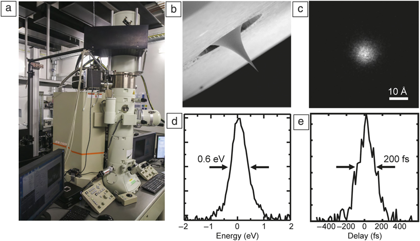
At the University of Göttingen, we recently implemented an advanced UTEM instrument using sharp field-emitter tips as an on-demand source of high-coherence ultrashort electron pulsesReference Feist, Bach, Rubiano da Silva, Danz, Möller, Priebe, Domröse, Gatzmann, Rost, Schauss, Strauch, Bormann, Sivis, Schäfer and Ropers49,Reference Feist, Echternkamp, Schauss, Yalunin, Schäfer and Ropers73 (Figure 4a–b). Specifically, we modified a commercial JEOL JEM 2100F field-emission transmission electron microscope, facilitating localized single-photon photoemission from a laser-triggered Schottky field emitterReference Yang, Mohammed and Zewail30,Reference Cook, Bronsgeest, Hagen and Kruit84 and synchronized optical sample excitation. Details on the instrument, comprehensive beam characterization, and prospects for future applications are outlined in Reference Reference Feist, Bach, Rubiano da Silva, Danz, Möller, Priebe, Domröse, Gatzmann, Rost, Schauss, Strauch, Bormann, Sivis, Schäfer and Ropers49.
Experimental setup and selected electron pulse properties of the Göttingen ultrafast transmission electron microscopy (UTEM) instrument. (a) A laser-driven Schottky field-emission electron gun is integrated with a custom modified JEOL JEM-2100F electron microscope. (b) Nanoscale photocathodes facilitate the generation of ultrafast electron pulses (c–e) down to 9-Å focal spot size, 0.6-eV energy width, and 200-fs pulse duration.Reference Feist, Bach, Rubiano da Silva, Danz, Möller, Priebe, Domröse, Gatzmann, Rost, Schauss, Strauch, Bormann, Sivis, Schäfer and Ropers49

In the limit of isolated single-electron emission, we achieved record electron-pulse properties, down to 9-Å electron focal spot size, 0.6-eV spectral width, and 200-fs pulse duration (Figure 4c–e). Within the duty cycle of the pulsed electron beam, peak brightness comparable to that of a conventional Schottky emitter is obtained, facilitating an ultralow transverse beam emittance down to 1.7 pm⋅rad.Reference Feist, Bach, Rubiano da Silva, Danz, Möller, Priebe, Domröse, Gatzmann, Rost, Schauss, Strauch, Bormann, Sivis, Schäfer and Ropers49 Besides the nanometer-probing capability using a sharply focused electron spot, the corresponding high degree of transverse coherence enables time-resolved variants of high-resolution phase-contrast imaging, electron holography, differential phase contrast scanning transmission electron microscopy, and diffraction from macromolecular and mesoscopic structures.
Notably, the emitter can be operated in conventional Schottky mode, facilitating standard TEM applications and in-depth sample characterization with µA of emission current. In photoelectron mode, the temporal structure of the beam is freely tunable from subpicosecond pulses to continuous operation, allowing for optimizing the maximum beam current to the requirements of a specific experiment. In the following, we describe the application of this instrument to the spatially resolved probing of strain dynamics using ultrafast convergent-beam electron diffraction (U-CBED).
Local diffractive probing of ultrafast strain dynamics in UTEM
In recent years, high-frequency optophononic devices operating in the MHz to THz range, such as toroidal microcavities,Reference Armani, Kippenberg, Spillane and Vahala85 suspended membrane structures,Reference Eichenfield, Chan, Camacho, Vahala and Painter86 or tailored multilayers, have shown great potential for advanced metrology and sensing applications.Reference Aspelmeyer, Kippenberg and Marquardt87–Reference Volz, Ordonez-Miranda, Shchepetov, Prunnila, Ahopelto, Pezeril, Vaudel, Gusev, Ruello, Weig, Schubert, Hettich, Grossman, Dekorsy, Alzina, Graczykowski, Chavez-Angel, Sebastian Reparaz, Wagner, Sotomayor-Torres, Xiong, Neogi and Donadio89 The characterization of these devices utilizing high-resolution and ultrafast optical spectroscopies has provided a deep understanding of their optical properties, but only indirectly gave access to the their phononic degrees of freedom and are often limited to micrometer-length scales. Ultrafast diffractive probing in UTEM offers unique capabilities to locally track the transient structural distortions in reciprocal space on femtosecond time scales,Reference Barwick, Park, Kwon, Baskin and Zewail90–Reference Cremons, Plemmons and Flannigan92 with exciting opportunities such as the mapping of phase transitions in intense optical near fields or the imaging of tailored nanoscale phononic wave fields.
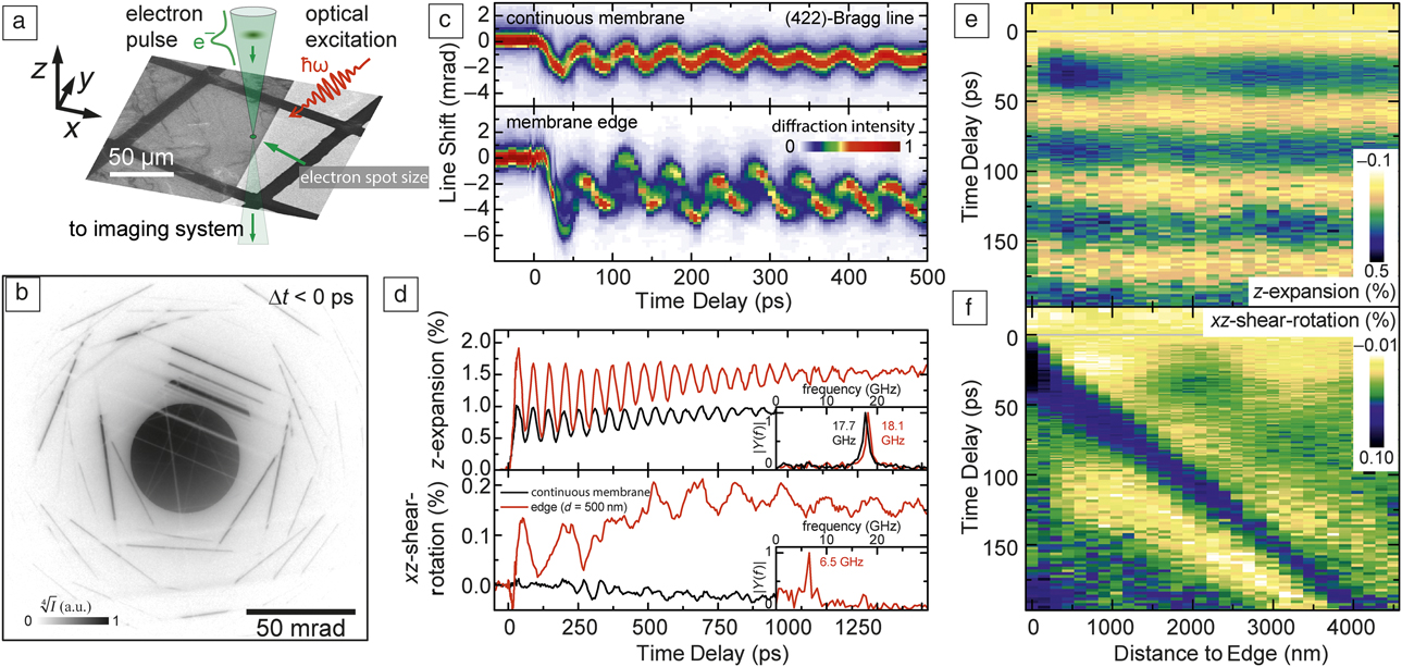
As a first example of U-CBED with a high-coherence electron source, we investigated the light-induced phononic wave field at the edge of a single-crystalline graphite membrane (Figure 5a).Reference Feist, Rubiano da Silva, Liang, Ropers and Schäfer93 The structure is illuminated with femtosecond laser pulses (50-µm focal spot size, 800-nm central wavelength, 50-fs pulse duration, 16-mJ/cm2 optical fluence), and we diffractively probed the local structural distortion employing 700-fs electron pulses focused to a 28-nm diameter. An exemplary CBED pattern obtained is shown in Figure 5b. The electron focus contains a broad distribution of incidence angles on the sample, which is visible in the pattern as a central intense disc. For certain incidence angles, Bragg scattering conditions are fulfilled, appearing as line-like features in the CBED pattern.Reference Zuo and Spence83 The angular position and scattering intensity encodes the local unit cell structure and lattice temperature.
Ultrafast nanoscale diffractive probing of strain dynamics. (a) A laser-excited single-crystalline graphite thin film is probed close to its edge with a sharply focused electron beam (28-nm focal spot size). (b) Ultrafast convergent beam electron diffraction pattern. (c) Time-dependent profiles of the (422)-Bragg line recorded in (upper panel) a continuous part of the membrane and (lower panel) close to its edge (500-nm distance), displaying an oscillatory change in the average line position and pronounced modulations in the Bragg line shape. (d) Quantitative reconstruction of local deformation gradient tensor components for two probing positions, disentangling the optically excited acoustic breathing (upper panel) and shear mode (lower panel). A shear mode component is observed close to the crystal edge (red curves) and absent in the continuous part of the membrane (black curve). The insets show the Fourier transform magnitudes of the respective transients. (e–f) Spatiotemporal maps of the two distortion tensor components reveal the complex spatiotemporal strain dynamics at the crystal edge.Reference Feist, Rubiano da Silva, Liang, Ropers and Schäfer93 Note: d, distance from edge of membrane; Δt, delay time; I, diffraction intensity; Y, Fourier amplitude of distortion tensor component at frequency f; ω, optical angular frequency; ħ, reduced Planck’s constant.

Figure 5c displays the temporal change of the (422)-Bragg line for two probing positions, far from the membrane edge (upper panel) and at an edge distance of 500 nm (lower panel). In both cases, pronounced shifts and modulations of the Bragg line profiles are observed, but with a different temporal behavior for both probing positions.
A particular strength of ultrafast diffractive probing is the ability to obtain quantitative information on structural distortions. By considering the temporal change of the mean position of a larger number of Bragg lines, we extract the dominant components of the local distortion tensor and thereby identify the character of the light-triggered phononic modes, as plotted in Figure 5d. For both probing positions, optical excitation launches a longitudinal acoustic wave propagating in the out-of-plane direction, resulting in an oscillatory change in the film thickness (breathing mode). Its characteristic frequency of about 18 GHz (Figure 5d, upper insets) is given by the round-trip time of the wave. Close to the membrane edge, a shear-rotational mode is also observed (Figure 5d, lower panel, red curve) with a frequency corresponding to the sound velocity of a transverse acoustic wave. We located the origin of the shear mode excitation by mapping the spatiotemporal evolution of the distortion tensor. Whereas the film breathing mode (Figure 5e), is found at all sample positions with an approximately constant amplitude and phase, the shear-rotational component (Figure 5f) exhibits a distinct spatial dependency—starting at the edge of the membrane, the first maximum of the shear-rotational mode amplitude shows a linear relation to the distance from the membrane edge. This peculiar coupling of nanoscale phononic modes was qualitatively reproduced in a continuum mechanics model that included the ultrafast heating of the graphite lattice.Reference Feist, Rubiano da Silva, Liang, Ropers and Schäfer93
In addition to the average local structural distortion, the Bragg line profiles in ultrafast CBED contain detailed information on the strain distribution within the depth of the membrane. In particular, the transient splitting of line profiles visible in Figure 5c (lower panel) is caused by the inhomogeneous structural deformation of the traveling strain waves bouncing between the two membrane faces. Such rich experimental data may further elucidate the role of ballistic transport of optically generated carriers and high frequency (thermal) phonons and their mode-specific coupling to an average thermal stress.
Further perspectives
The development of ULEED and the use of laser-triggered field emitters in UTEM are both still in their early stages. However, the first experiments have already shown the great benefit of localized photoelectron sources in these applications. We expect that ULEED will serve as a unique and strong complement to photoemission spectroscopy in ultrafast surface science, elucidating the dynamics of tailored surface excitations and contributing to the understanding and control of low-dimensional structural phase transitions. UTEM, on the other hand, is an incredibly versatile experimental platform, which will continue to grow in terms of its range of applications from time-dependent versions of local electron diffraction, imaging, and spectroscopy to phenomena and approaches not encountered in conventional electron microscopy, including quantum optics with free-electron beams or attosecond phenomena.Reference Echternkamp, Feist, Schäfer and Ropers94,Reference Priebe, Rathje, Yalunin, Hohage, Feist, Schäfer and Ropers95 We believe that coherent ultrafast electron sources will play an essential role in each of these aspects within the emerging field of ultrafast nanoscale imaging.
Acknowledgments
We gratefully acknowledge the collaboration with our co-authors on the works discussed here. This work was funded by the Deutsche Forschungsgemeinschaft (DFG-SFB-1073, Project A05, and DFG-SPP-1840), the VolkswagenStiftung, and the European Research Council (ERC-StG “ULEED,” ID: 639119).

Armin Feist is a doctoral candidate at the University of Göttingen, Germany. He received his BSc degree from the University of Leipzig, Germany, and his MSc degree from the University of Göttingen, Germany, both in photonic crystals and laser-triggered field ion microscopy. His current research focuses on the development and application of ultrafast transmission electron microscopy using coherent electron pulses, nanoscale structural dynamics, optically tailored free-electron beams, and the exploration of new instrumental capabilities in ultrafast transmission electron microscopy. Feist can be reached by email at armin.feist@uni-goettingen.de.

Gero Storeck is a doctoral candidate in the Department of Physics at the University of Göttingen, Germany. He received his bachelor’s degree in 2011 and his master’s degree in 2014 from the University of Göttingen. His research interests include the development of new electron sources and ultrafast surface science. Storeck can be reached by email at gero.storeck@uni-goettingen.de.

Sascha Schäfer is a professor of solid-state physics at the University of Oldenburg, Germany. He studied chemistry at the Technical University of Darmstadt, receiving his PhD degree in physical chemistry. After completing postdoctoral work at the California Institute of Technology, he joined the University of Göttingen as a senior scientist. His newly established group in Oldenburg is funded by a Lichtenberg professorship of the Volkswagen Foundation and focuses on the investigation of ultrafast nanoscale dynamics using time-resolved electron imaging. His awards include the Alarich-Weiss Award, the Bernhard Hess Lectureship (University of Regensburg), the Heinrich Rohrer Rising Medal (Surface Science Society of Japan) and the Walter-Schottky Prize (German Physical Society). Schäfer can be reached by email at sascha.schaefer@uni-oldenburg.de.

Claus Ropers is a professor of solid-state physics at the University of Göttingen, Germany. He studied physics at the University of Göttingen and the University of California, Berkeley, and received his PhD degree for doctoral research at the Max Born Institute, Humboldt University, Berlin. His research group develops and applies novel experimental tools for the study of ultrafast structural, electronic, and spin dynamics, including ultrafast transmission electron microscopy and diffraction. His awards include the Carl-Ramsauer Prize, Walter-Schottky Prize (German Physical Society), Klung-Wilhelmy Science Prize, and Gottfried-Wilhelm-Leibniz Prize (German Research Foundation). Ropers can be reached by email at claus.ropers@uni-goettingen.de.