Introduction
The slotted array antennas fed by the rectangular waveguides are employed broadly as a receiving or transmitting antenna in radar and communication systems [Reference Elliot1–Reference Prakash, Christopher and Balakrishnan7]. They present some unique features, which are attractive for antenna designers. Some of the main specifications are their high power handling, high efficiency, and incorporated feeding and radiating systems [Reference Elliot1–Reference Prakash, Christopher and Balakrishnan7]. Among various kinds of the slotted array antennas fed by the rectangular waveguides, the edge slot antennas are used in radar systems when the scanning of the main beam of the antennas in the H-plane is necessary [Reference Lo and Lee4]. The performed study has also shown that the frequency bandwidth of the edge slot antennas is greater than the frequency bandwidth of the longitudinal slot antennas [Reference Lo and Lee4].
In the edge slot antennas fed by the rectangular waveguides, the inclined slots are cut in the narrow wall of the feeding waveguides. The inclined slots interrupt the surface current density associated with the dominant mode in the rectangular waveguides. This interruption in turn develops an electric field in the slot apertures and causes the radiation of the electromagnetic energy into the outer space [Reference Elliot1, Reference Volakis6]. It is known that the radiated energy by the edge slots increases as the inclination of the slots increases [Reference Elliot1, Reference Volakis6]. In other words, the edge slots with zero inclination do not radiate. To prevent the grating lobes for being appeared in the radiation pattern of the standing wave edge slotted array antennas, it is necessary to restrict the distance between successive slots to one-half of the guided wavelength. This can be easily achieved by changing the inclination of the successive slots alternatively [Reference Elliot1, Reference Volakis6].
Unfortunately, the alternative inclination of the neighboring slots introduces some undesirable lobes to the radiation pattern of the edge slot antennas, which are usually called the second-order beams [Reference Kurtz and Yee8]. Several methods have been proposed in the literature to eliminate the second-order beams [Reference Wang, Zhong, Jin and Liang9–Reference Caer and Le Foll25]. It is possible to classify them into two main groups. In the first group, the second-order beams are suppressed by employing the untilted slot antennas while the slot excitations are achieved by utilizing some appropriate obstacles established inside the feeding waveguides. In this regard, employing irises have been proposed as an effective method to excite the untilted edge slot antennas [Reference Wang, Zhong, Jin and Liang9–Reference Wang, Jin, Lu and Zhong13]. In other approaches, etched strips, suspended slot lines, or parasitic dipoles printed on some dielectric laminates have been used to excite the untilted edge slot antennas [Reference Hirokawa and Kildal14–Reference Giner, Valero-Nogueira, Herruzo and Escudero17]. Other researchers have proposed to employ bifurcated rectangular waveguide or double ridge waveguide to excite the untilted slot antennas [Reference Sangster18–Reference Moradian20]. It has been also shown that employing v-shaped edge slot antennas is also effective for suppressing the second-order beams [Reference Lu, Zhang, Wang, Liang, Ge, Jin and Wu21, Reference Wang, Zhang, Qi and Zhang22]. Other attempts have been proposed to utilize wires or flat metals to excite the untilted edge slot antennas [Reference Hirokawa, Manholm and Kildal23–Reference Caer and Le Foll25].
In the second category, the slots are inclined but other methods such as surrounding the slots into cavity boxes [Reference Brady26], placing strip grating in front of the antennas [Reference Brady26, Reference Chou, Lin, Lu, Chang and Tiong27], tuning the depth of the ground plane [Reference Chang, Hung, Lin, Lin, Ho and Lee28], and employing chokes with appropriate depth [Reference Bandyopadhyay, Banerjee, Chatterjee and Maiumder29, Reference Young, Kazama, Hirokawa and Ando30] have been proposed to suppress the second-order beams. It is worthwhile to note that employing these solutions lead to a bulky array antenna. Another attempt has proposed to rearrange the stacking sequence of each waveguide in the array such that the neighboring slots in the adjacent waveguides have opposite inclinations [Reference Park, Na, Kim and Lee31, Reference Li and Dou32]. Although employing this solution enables one to suppress effectively the second-order beams, it may not be appropriate in some applications which require a very low level of the cross-polarization.
In the edge slotted arrays, for any individual slot, the slot depth and its tilt cannot be selected based on the data associated with the slots when they are isolated. This is something unavoidable that comes from the fact that the mutual coupling between any individual slot and other slots in the arrays contributes to the developed voltage inside the slot. Depending on the array specifications and the slot arrangement, the portion of the developed voltage inside the slots which is attributed to the mutual coupling between the slots may have lagged or leaded phase to the phases of the developed voltages associated with the internal forward and backward waves pass internally under the slot. This lagged or leaded phase differences can be translated as an extra inductive or capacitive part in the equivalent shunt admittance model of the slots. To compensate for the effect of the mutual coupling, the slot depths are changed such that these extra inductive or capacitive parts are canceled out by the inductive or capacitive parts of the normalized equivalent self-admittance of the slots. In the same manner, the resistive parts associated with the mutual coupling are compensated by changing the slot tilts such that the desired slot voltage is achieved. From the performed discussion, one can conclude that the array optimum specifications (desired slot excitations and the proper input admittance at each branch of the array) can be achieved if and only if the slots have the normalized equivalent self-admittance with adequate dynamic range.
Although all the introduced slot antennas are valuable, in the author's idea, their equivalent normalized admittances should be studied more in-depth before one can employ any of them to design a high-performance antenna. It means that if the equivalent normalized self-susceptance of any of the introduced slot antennas around the resonance would be a linear function of the slot depth (i.e. it should cross zero for a special value of the slot depth for which the equivalent normalized self-conductance is maximum), one can conclude that the designated slot antenna can be employed to design a high-performance array of slots. That is because one can make sure that the destructive effect of mutual coupling on the performance of the arrays can be effectively compensated.
Here, the equivalent normalized self-admittance of the untilted slot antenna excited by tilted wires is studied. It is shown that for these types of the slot antennas, the equivalent normalized susceptance does not even cross zero at resonance (it is assumed that at resonance, the equivalent normalized conductance is maximum). This shortcoming has prevented a designer to compensate for the effect of the mutual coupling in the array effectively such that both of the prescribed slot voltages as well as the input admittance are not achieved. The proposed idea enables a designer to control the equivalent normalized susceptance of any elements in the arrays in an appropriate range such that the compensation of the mutual coupling can be easily accomplished. In the next sections, the important characteristics of the proposed untilted edge slot antennas are studied.
The proposed untilted edge slot antennas
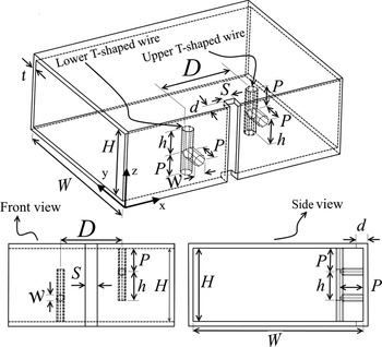
Figure 1 shows the proposed untilted edge slot antenna together with its different parameters. According to the figure, the slot has no tilt. Furthermore, two T-shaped wires are placed on both sides of the slot. One of the T-shaped wires attaches the upper broad wall of the waveguide to the narrow wall of the waveguide which contains the slot. Similarly, the other T-shaped wire attaches the lower board wall of the waveguide to its narrow wall. Furthermore, the T-shaped wires are perpendicular to the direction of the waveguide. As the figure shows, the T-shaped wires are not symmetric. For each T-shaped wire, two arms have similar lengths which are denoted by P. Another arm of the T-shaped wire has a different length which is denoted by h. The distance between the T-shaped wires and the diameter of the wires is denoted by D and w, respectively. The slot width and its depth are also denoted by S and d, respectively. Finally, the waveguide width, height, and thickness are denoted by W, H and t, respectively.
The proposed untilted edge slot antennas excited by the T-shaped wires including its parameters.

The T-shaped wires direct the conductive current from the upper broad wall of the waveguide toward the narrow wall of the waveguide to feed the untilted edge slot. From the circuit point of view, the L-shaped parts of the T-shaped wires are equivalent to a lumped inductance. Similarly, the free arms act as a capacitor. So, one can select the proper length for the free arms such that it would be possible to eliminate the inductive effect associated with the L-shaped parts. Because it is not possible to investigate the effect of all parameters on the characteristics of the proposed edge-slot antennas, some of the physical parameters are fixed. Table 1 demonstrates the chosen values of the different dimensions. Hence, the distance between the T-shaped wires (D), the lengths of the T-shaped wire arms (P and h), and the slot depth (d) are selected as the main parameters of the antenna to investigate the antenna characteristics. Besides, in the current article, all the simulations have been performed at 3 GHz.
Dimensions of the proposed untilted edge slot antennas

Investigation of the effect of the T-shaped wire parameters on the performance of the proposed untilted edge slot antennas
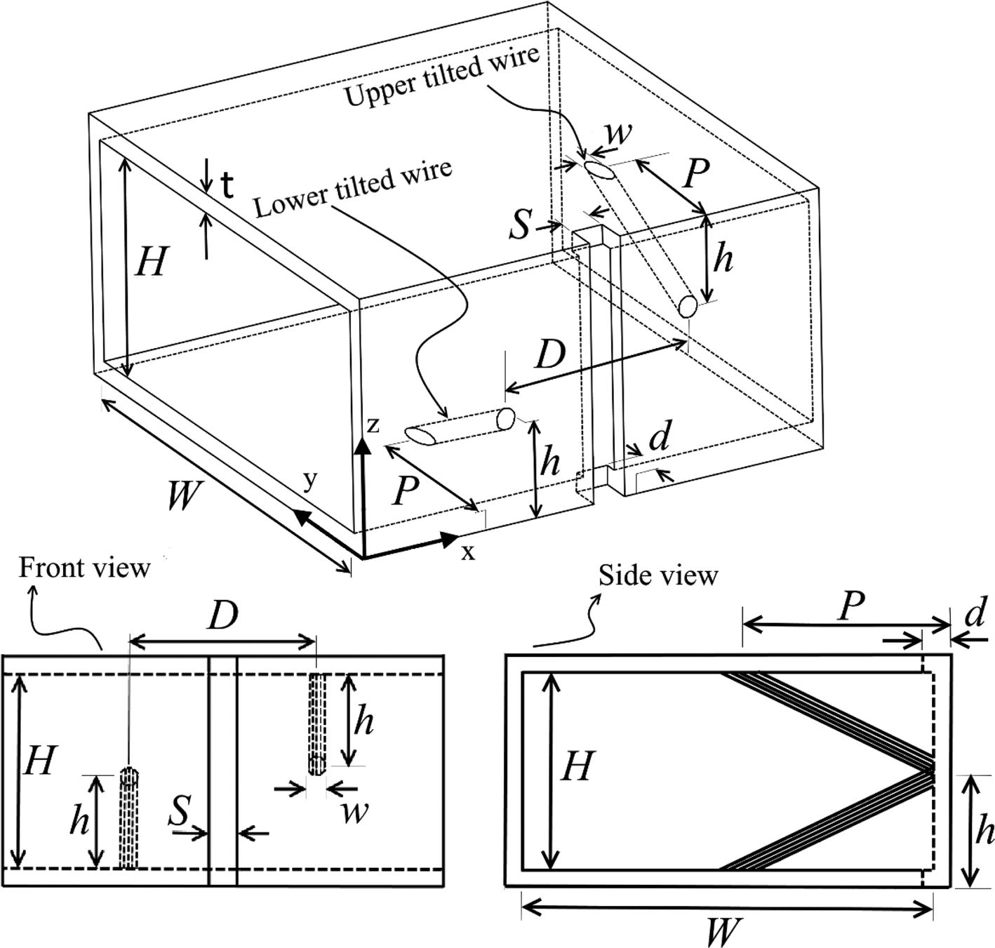
Before the different characteristics of the proposed untilted slot antenna are examined, it is worthy to investigate the equivalent normalized admittance of the untilted edge slot antenna excited by tilted wires. Figure 2 shows the untilted edge slot antenna fed by tilted wires together with its different parameters. Most of the physical parameters of the antennas are similar to the proposed untilted edge slot antennas (see Fig. 1). As the figure shows, one end of the wire starts in the middle of the narrow wall while the other ends terminate at the broad wall of the waveguide. The extension of the tilted wires into the waveguide is denoted by P and is considered here as one of the antenna parameters to study the characteristics of the antennas. The parameter h is selected equal to H/2. To investigate the equivalent normalized admittance of these types of antennas, a model of the proposed untilted edge slot antennas has been defined in Ansys High-Frequency Structure Simulator (HFSS) and simulated at 3 GHz. The waveguide width and its height, the wire diameters, and the width of the slot are similar to the dimension of the proposed untilted edge slot antennas listed in Table 1. The waveguide ports of the model are extended to the middle of the slot to find the actual equivalent normalized admittance of the slot antennas.
The untilted edge slot antenna excited by the tilted wires.

The equivalent normalized admittance of the antennas has been obtained for three different separations of tilted wires. The selected values are equal to 14, 20, and 26 mm. The simulation of the model for each separation of the tilted wires has been done while the slot depth (d) and the extension of the tilted wire into the waveguide (P) have also been swept. The equivalent normalized self-admittance of the antennas has been easily derived from the simulated reflection coefficients of the model and using the following equation.

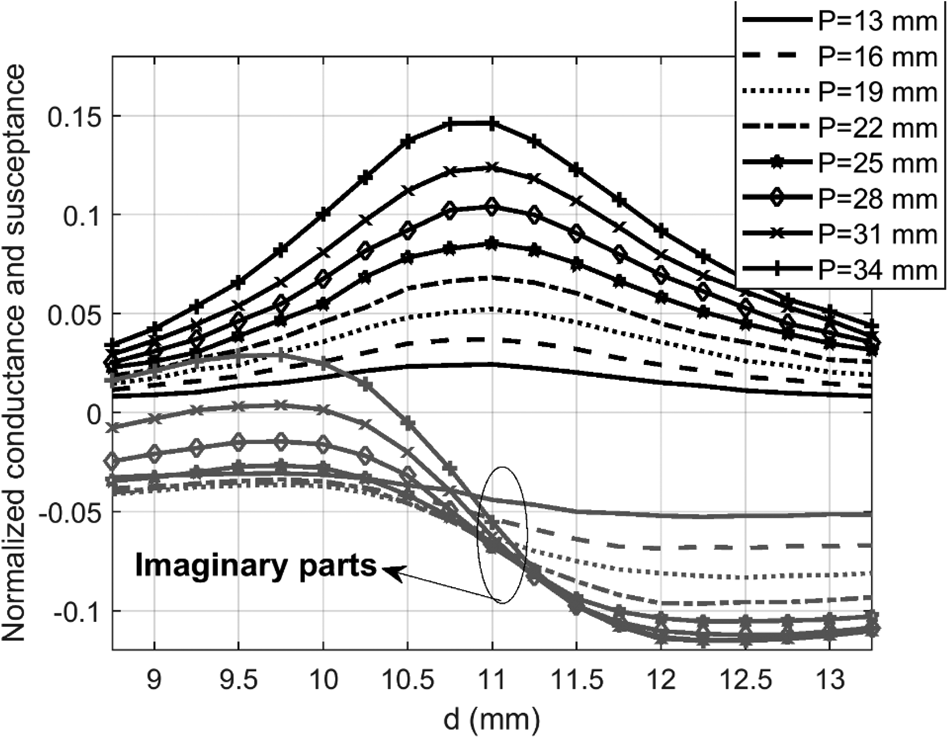
where G 0 is the characteristic admittance of the equivalent transmission line. Figure 3 shows the obtained equivalent normalized self-admittance of the simulated model when the distance between the tilted wires (D) is equal to 26 mm. The figure demonstrates the equivalent normalized self-admittance of the antennas versus the slot depth (d) and for various extensions of the tilted wires into the waveguide (P). From Fig. 3, it is observed that as a result of the increment of P, the equivalent normalized conductance of the antennas also increases. The figure shows that for small values of P, the equivalent normalized susceptance of the antennas is always negative. So, it is not possible to define the slot depth for which the slot antennas go to resonance. According to the figures, even for large values of P, the equivalent normalized susceptance does not cross zero at the slot depth (d) for which the equivalent normalized conductance is maximum. Hence, the definition of the resonant depths for large P is also confusing. Overall, from Fig. 3, one can conclude that for the untilted edge slot antenna fed by the tilted wires, the dynamic range of the imaginary part of the equivalent normalized admittance is not enough. In a high performance slotted arrays, all the array elements must have an adequate dynamic range for compensating the effect of the mutual coupling to achieve the prescribed slot excitations. Besides, as it will be shown later, even if one considers the resonant depth of the slot equal to the slot depth for which the equivalent normalized conductance of the slots is maximum, the designed array based on this definition does not show acceptable performance. For other tilted wire distances (i.e. 14 and 20 mm), similar behavior was observed. So, for other distances between the tilted wires, the definition of the resonant depths was also confusion and the dynamic range of the equivalent normalized susceptance was limited. It is worthwhile to mention here that as the distance between the tilted wires increases, the equivalent normalized conductance (the radiated power by the slot antennas) decreases.
The equivalent normalized self-admittance of the untilted edge slot antenna fed by tilted wires versus the slot depth when the distance between the wires is equal to 26 mm.

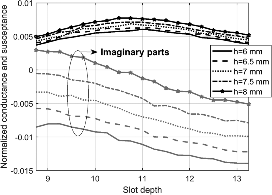
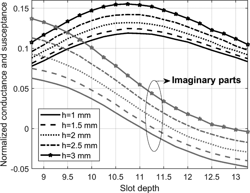
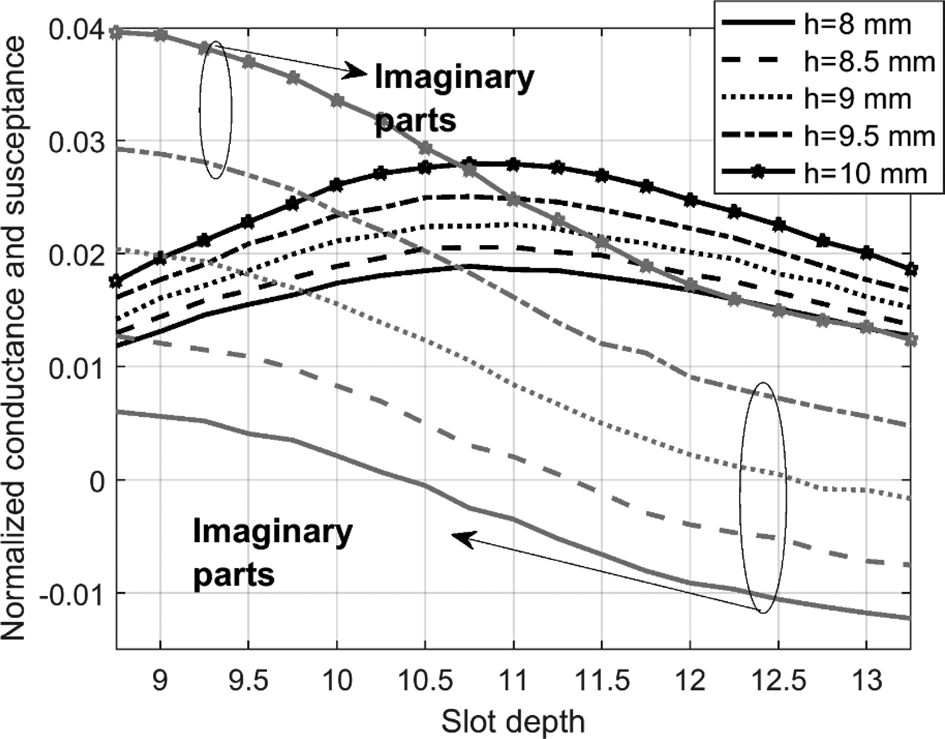
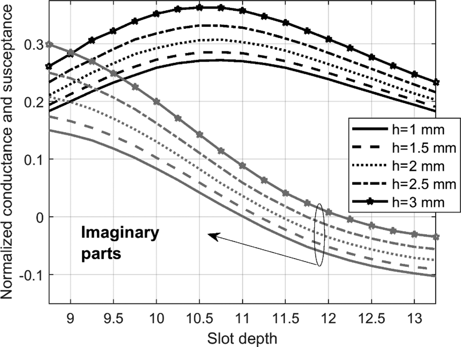
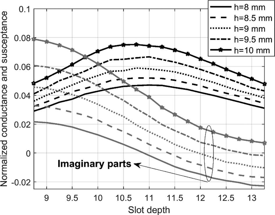
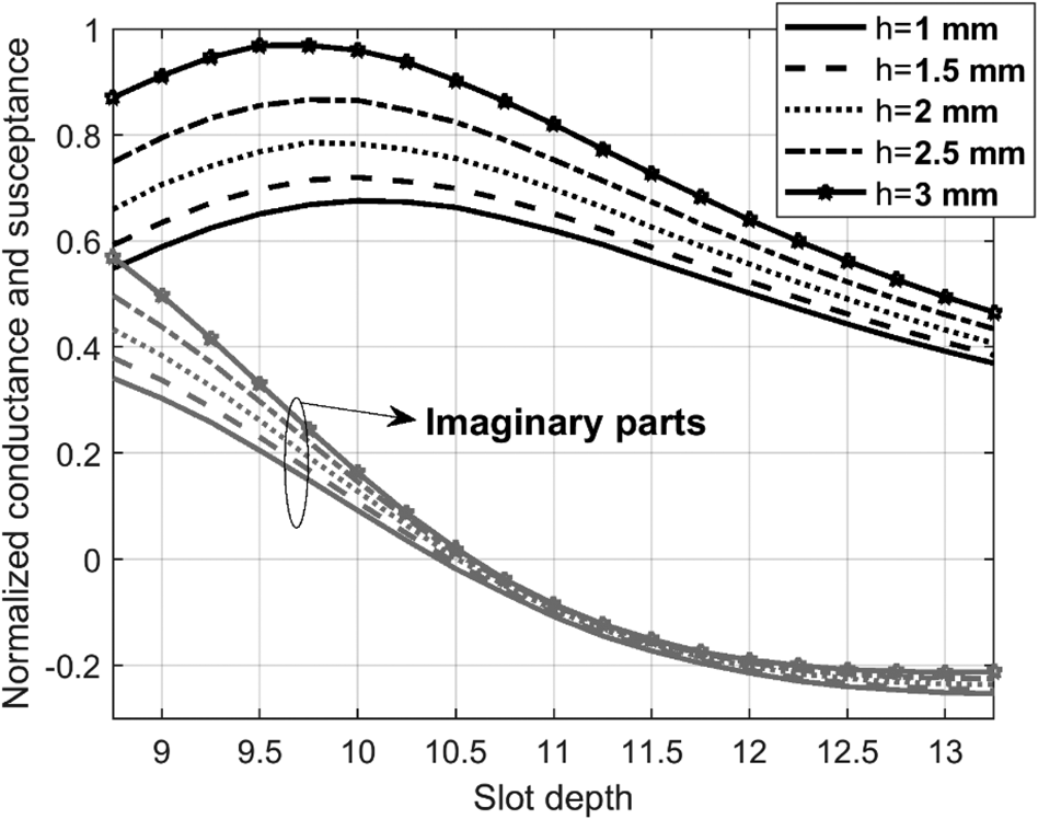
The discussed shortcoming of the untilted slot antennas excited by the tilted wires can be effectively eliminated if the tilted wires are replaced by the T-shaped wires. To find the characteristics of the proposed untilted slot antennas fed by the T-shaped wires, a model of the antennas is defined and parameterized in HFSS. Then, the simulation of the model has been carried out while the slot depth (d) and the lengths of the arms (P and h) are swept in some appropriate intervals. The equivalent normalized admittance of the slot antennas has been found from the simulated reflection coefficient of the model and employing equation (1). Figures 4–9 show the equivalent normalized admittance of the proposed edge slot antennas versus the slot depth and for various h. Figures 4, 6, and 8 were obtained when the parameter P was selected equal to 8 mm. Similarly, for Figs 5, 7, and 9, the parameter P is equal to 18 mm. Besides, for Figs 4 and 5, the parameter D is equal to 26 mm. For Figs 6 and 7, the parameter D is equal to 20 mm. Finally, for Figs 8 and 9, the parameter D is equal to 14 mm.
The variation of the equivalent normalized admittance of the proposed edge slot antennas versus the slot depth and for various h when D and P are equal to 26 and 8 mm, respectively.

The variation of the equivalent normalized admittance of the proposed edge slot antennas versus the slot depth and for various h when D and P are equal to 26 and 18 mm, respectively.

The variation of the equivalent normalized admittance of the proposed edge slot antennas versus the slot depth and for various h when D and P are equal to 20 and 8 mm, respectively.

The variation of the equivalent normalized admittance of the proposed edge slot antennas versus the slot depth and for various h when D and P are equal to 20 and 18 mm, respectively.

The variation of the equivalent normalized admittance of the proposed edge slot antennas versus the slot depth and for various h when D and P are equal to 14 and 8 mm, respectively.

The variation of the equivalent normalized admittance of the proposed edge slot antennas versus the slot depth and for various h when D and P are equal to 14 and 18 mm, respectively.

Some facts are revealed by the figures. First, as the parameter h increases, all the curves shift upward. In the same manner, as the parameter D decreases or the parameter P increases, the equivalent normalized conductance increases. So, if the extension of the T-shaped wires into the waveguide increases or the separation between them decreases, one can see greater radiation of the electromagnetic energy by the slot. Second, for some values of the parameter h, when the equivalent normalized susceptance is approximately equal to zero, the equivalent normalized conductance is maximum. This means that one can select the extension of the T-shaped wires into the waveguide (namely P) or the separation between them (namely D) in a wide range while making sure that the slots resonate if the parameter h is selected properly. Comparing Figs 4–9 with Fig. 3 shows that by choosing the proposed slot antennas rather than the untilted edge slot antennas fed by the tilted wires, one has better control to the dynamic range of the equivalent normalized admittance.
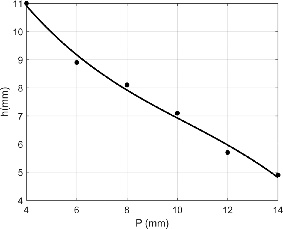
To find the appropriate h against the parameter P, the simulation of the model for separation of the T-shaped wires (namely D) equal to 14 mm has been performed when the parameter h was swept in a fine interval. Hence, the appropriate h against the parameter P was derived for the proposed untiled edge slot antennas when the separation of the T-shaped wires was equal to 14 mm. Figure 10 shows the appropriate h against the parameter P. It is clear that if one selects another value for the separation of the T-shaped wires, the derived curve in Fig. 10 is not applicable anymore.
The appropriate length of the free vertical arms of the T-shaped wires (namely h) versus the extension of the T-shaped wires into the waveguides (namely P).

The equivalent normalized admittance versus frequency has also been studied. In this regard, the equivalent normalized admittance versus frequency has been derived for the proposed edge slot antennas and the edge slot antennas fed by the tilted wires. For both cases, the separation between the wires has been selected equal to 14 mm. For the edge slot antennas fed by the tilted wires, the equivalent normalized admittance has been derived for various extensions of the tilted wires into the waveguide (namely P). Furthermore, the slot depth has been selected equal to 10 mm. The results show that as the extension of the tilted wires into the waveguide increases, the equivalent normalized conductance increases. Furthermore, the equivalent normalized susceptance is negative from 2.5 to 3.5 GHz.
Similarly, for the proposed edge slot antennas, the slot depth has been selected equal to 11 mm. The results show that the dynamic range of the equivalent normalized admittance has been improved significantly in comparison to the edge slot antennas fed by the tilted wires. In addition, the results show that as the extension of the T-shaped wires (namely P) increases, the equivalent normalized conductance increases while the resonant frequency slightly decreases. The results also show that for every P, the equivalent normalized susceptance is roughly zero when the equivalent normalized conductance is maximum.
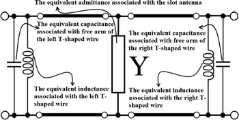
Based on the performed discussions, one can consider an equivalent circuit for the proposed slot antennas which is shown in Fig. 11. In the figure, the central admittance is associated with the radiated and the stored electromagnetic energy by the slot. The other elements are associated with the T-shaped wires. Please note that at resonance, the inductance and the capacitance in the model cancel out each other. So, they can be omitted from the model (i.e., infinite impedances). In the next section, more characteristics of the proposed untilted edge slot antennas will be discussed while the main parameters of the slot antennas are limited to only the slot depth (namely d) and the extension of the T-shaped wires (namely P) into the waveguide.
The equivalent model for the proposed edge slot antennas.

Obtaining the designing curves for the proposed edge slot antennas using the infinite array approach
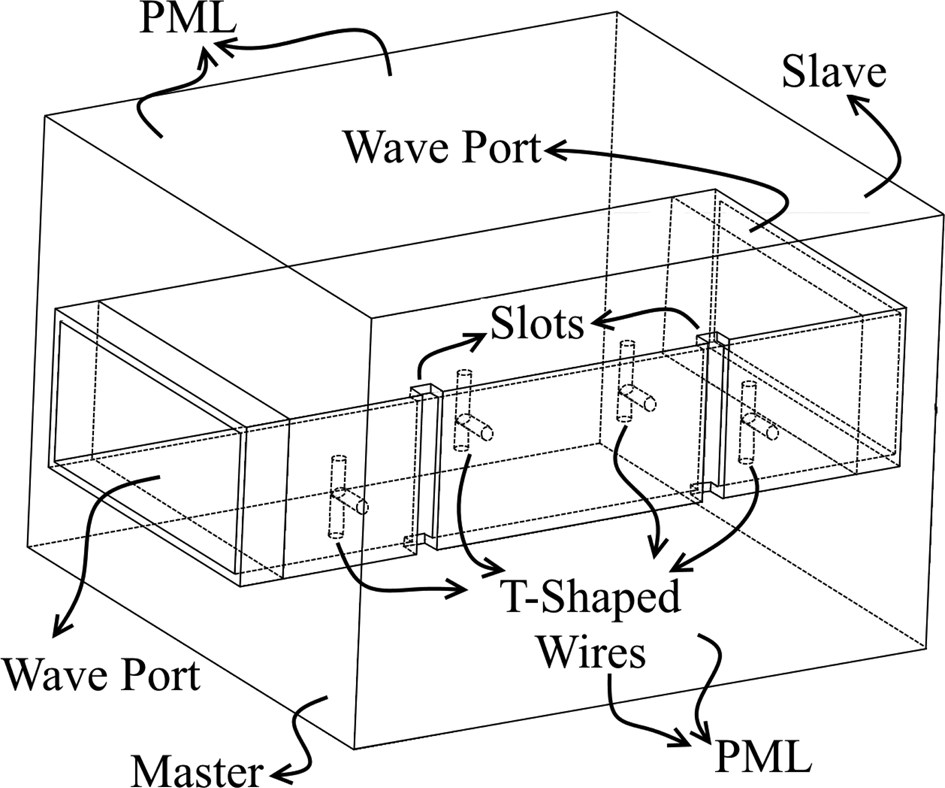
As it was described in the previous section, all the dimensions of the proposed slot antennas have been fixed and only the slot depth (namely d) and the extension of the T-shaped wires into the waveguides (namely P) are left as the main parameters which control the proposed antenna characteristics. Please note that the length of one arm of the T-shaped wires (namely h) is represented by the length of the other arms of the T-shaped wires. So, it is not left as the antenna parameters. To design a high-performance array of the proposed edge slot antennas, it is necessary to know the resonant conductance of the proposed slot antennas versus P when the mutual coupling between the slots is present. Besides, for each P, it is also necessary to find the required slot depths (namely d) for which the slot resonates. These data are usually demonstrated as some graphs. These graphs can then be used to design arrays of the proposed edge slot antennas. To find the required resonant conductances as well as the resonant depths, it is assumed that the array containing the slots is large and the variation of the slot excitations is smooth. This leads one to employ the infinite array approach to find the resonant conductances and the resonant depths of the slots. To accomplish this goal, a unit cell composed of two successive slots of the proposed untilted edge slot antennas has been drawn in HFSS. Figure 12 shows the model including some of its features. As it is seen by the figure, a master and a slave boundary conditions are assigned to the two faces of the bounded air box. Because the proposed untilted edge slot antennas will be used in a linear standing wave antenna, the phase delay between the master and slave boundaries has been set to zero degrees. Other boundaries have been forced to be the perfect match layer. The simulation of the unit cell has been performed when the parameter P and d have been swept in some necessary intervals. Then, the reflection coefficient of the model has been used to derive the required design curves.
The employed mode to obtain the resonant conductance and depth of the proposed untilted edge slot antennas.

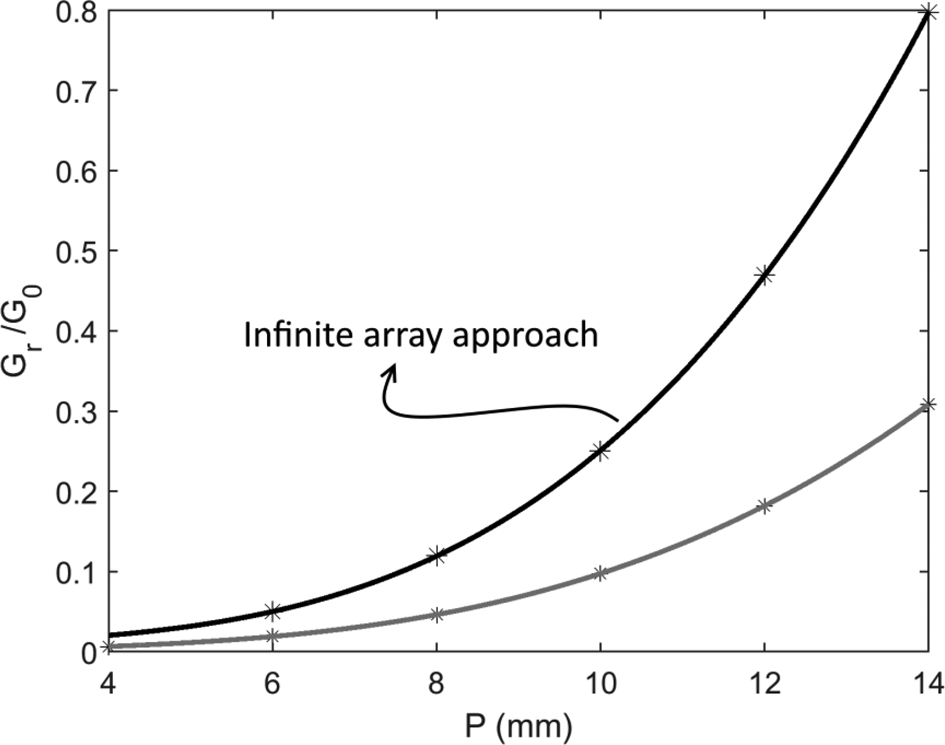
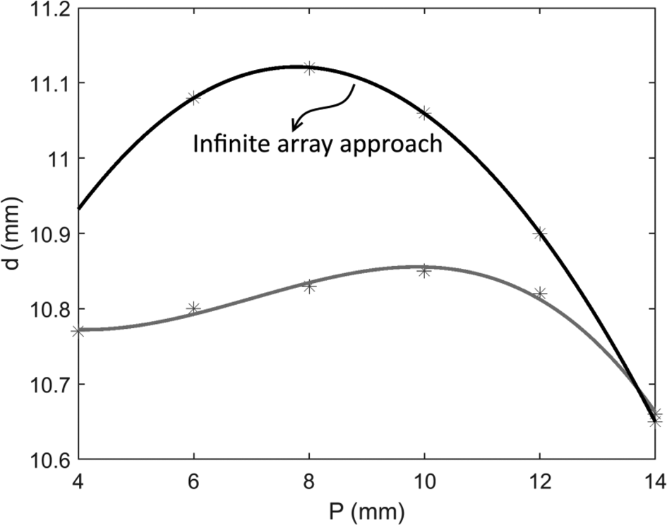
The normalized resonant conductance of the proposed untilted edge slot antennas versus the parameter P is shown in Fig. 13. For comparison reasons, the normalized resonant self-conductance of the proposed antennas is also included in the figure. The figure shows that for any P, the resonant self-conductance is much smaller than the resonant conductance (derived from an infinite array approach). This clearly shows the significance of the mutual coupling between the antenna elements [Reference Li, Meng and Dou33]. As the figure shows, the normalized resonant conductance increases as the parameter P increases. The provided curve which is associated with the infinite array approach can be used to find the required parameter P for each slot in linear arrays according to the prescribed array excitations. Another important parameter that is required to design a linear array of the proposed untilted slot antennas is the resonant length of the slots versus the parameter P. The resonant length of the proposed untilted slot antennas versus the parameter P is shown in Fig. 14. As seen by the figure, for P approximately <8 mm, the resonant depth of the proposed slot antennas increases as the parameter P increases while for other portion of the curve, the resonant depth decreases as the parameter P increases. The resonant depth of the proposed untilted edge slot antennas when they are isolated is also added to the figure. It is seen by the figure that except for the large values of P, the resonant depth of the isolated slot antennas is always smaller than the resonant depth of the slot antennas in the infinite array. The provided curve which is related to the infinite array approach can be used to find the required depth of each slot in the linear arrays that consist of the proposed untilted edge slot antennas.
The variation of the conductance of the proposed untilted edge slot antennas versus the extension of the T-shaped wires into the waveguides (namely P).

The variation of the resonant depth of the proposed untilted slot antennas versus the extension of the T-shaped wires into the waveguides (namely P).

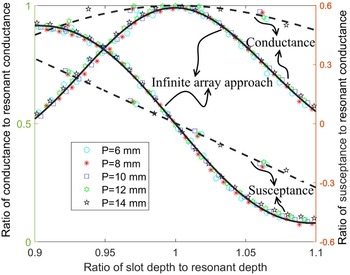
As it was explained in the previous sections, one important aspect of the proposed untilted edge slot antennas is its significant dynamic range of the equivalent normalized self-admittance which enables a designer to effectively compensate for the mutual coupling between the slots. Hence, it is worthy to obtain the variation of the normalized equivalent admittance of the proposed slot antennas against the normalized slot depth (i.e. the ratio of the slot depth to the resonant slot depth). Figure 15 shows the normalized equivalent conductances and susceptances of the proposed slot antennas when the antennas are isolated or they are placed in an infinite array. According to the figure for the isolated slot antennas, the dynamic range of the equivalent normalized admittances is sufficient. So, one can devise the proposed edge slot antennas in high-performance slotted array antennas while being confident that the mutual coupling between the array elements will be compensated effectively. The figure also shows that the equivalent normalized admittance of the isolated antennas is smothered than the equivalent normalized admittance of the antennas in an infinite array. The sharper variation of the equivalent normalized admittance is translated to a smaller frequency bandwidth if slotted array antennas are realized.
The normalized conductance and susceptance of the proposed untilted edge slot antennas versus the normalized slot depth.

It is also worthwhile to mention here that there is no limitation on employing the proposed edge slot antennas in the high-performance traveling edge slotted arrays. Please note that in a traveling slot antenna that consists of the proposed slot antennas, the progressive phase difference between the neighboring slots is achieved by changing the orientation of the T-shaped wires alternatively and selecting an appropriate distance between the slots. As the distance between the neighboring slots in the traveling wave slotted arrays is not equal to one-half of the guiding wavelength, the provided graph in Figs 13–15 cannot be used to design a traveling slotted array. Instead, one has to find the new incremental admittance data by selecting the proper spacing between the slots in the model presented in Fig. 12.
Designing an array consists of the proposed untilted edge slot antennas and the results
The proposed untilted edge slot antennas are employed to design a linearly resonant slotted array that consists of 11 slots at 3 GHz. The excitation of the array elements is selected to be Dolph–Chebyshev distribution such that the side-lobe level of the array will be −20 dB in the E-plane. For each slot in the array, the extension of the T-shaped wires into the feeding waveguide (namely P) and the slot depth (namely d) can be easily derived by employing the thick black curves in Figs 13 and 14. In this regard, the following guidelines can be followed:
• Find the required voltage excitation of the array according to the prescribed antenna pattern specifications.
• Determine the resonant conductance of each array element by assuming that for each slot, the resonant conductance of the slot is proportional to the squared of its previously obtained voltage excitation.
• For each resonant conductance find the associated extension of the T-shaped wires into the feeding waveguide (namely P) from Fig. 13.
• From the obtained extensions of the T-shaped wires into the waveguide, find the required slot depth (namely d) from Fig. 14 for each slot.
The physical dimensions of the designed array are given in Table 2. The spacing between the adjacent slots in the designed array is 69.4 mm. To better demonstrate the advantage of the proposed edge slot antennas over the edge slot antennas fed by the tilted wires, another linear array that consists of the edge slot antennas fed by the tilted wires and with similar specifications has been designed. To design the array, the presented curves in Fig. 3 are used and it is supposed that the antennas resonate when the equivalent normalized conductance is maximum (i.e. only the peaks of the equivalent normalized conductance have been used to design the array). Table 3 shows the physical dimensions of the designed array.
Dimensions of the first designed linearly resonant slotted array antenna in mm

Dimensions of the second designed linearly resonant slotted array antenna in mm

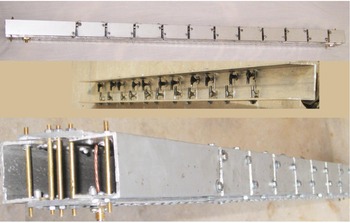
To implement the designed array, first, the slots were cut into an aluminum hollow tube. Then the tube was cut into two pieces along its centerline. After the T-shaped wires are attached to the piece containing the slots, the two pieces are joined together by two aluminum bars and rivets. Figure 16 shows the implemented antenna. To feed the antenna, a simple SMA to the rectangular waveguide is employed. For a better demonstration of the transition from SMA to the rectangular waveguide, a photograph of the transition is also added to Fig. 16. As the figure shows, the transition is very simple. A copper probe with a diameter equal to 3 mm is soldered to the inner conductor of the SMA and extended straight into the waveguide. Although the probe length was found to be roughly one-half of the waveguide height, in the actual array, its length was selected longer for better impedance matching (50 Ohm). Besides, the required short circuit at both sides of the antenna is realized by some parallel wires instead of terminating conductive walls. To better clarify the positions and the orientations of the T-shaped wires inside the waveguide, a photograph of the antenna while the waveguide broad walls are cut is also included in Fig. 16.
Photographs of the implemented antenna.

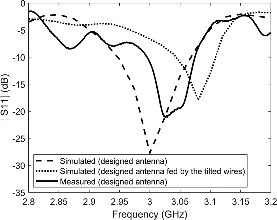
The simulation of the designed antenna has been carried on using HFSS. The measurement of the reflection coefficient of the implemented antenna has also been performed. Figure 17 shows the simulated and measured reflection coefficients. The figure shows that the simulated reflection coefficient is better than −10 dB from 2.95 to 3.07 GHz while the measured reflection coefficient is better than −10 dB from 2.99 to 3.08 GHz. From the figure, it is also observed that the measured bandwidth of the designed antenna is smaller than the simulated bandwidth. Besides, the measured reflection coefficient is shifted about 40 MHz from the center frequency (i.e. 3 GHz). The reduction of the frequency bandwidth and the small shift in the center frequency of the implemented antenna is due to the large construction tolerances. For comparative reasons, the simulated reflection coefficient of the second designed array composed of the untilted edge slot antennas fed by the tilted wires is also added to the figure. According to the figure, the reflection coefficient of the antenna at 3 GHz (center frequency) is poor. Furthermore, the frequency bandwidth of the antenna is small in comparison to the array composed of the proposed edge slot antennas. One may try to tune the parameters of the designed array (i.e. parameters P and d) such that the center frequency is shifted to 3 GHz. However, it is a blind and time-consuming process.
The reflection coefficients of the designed array versus frequency.

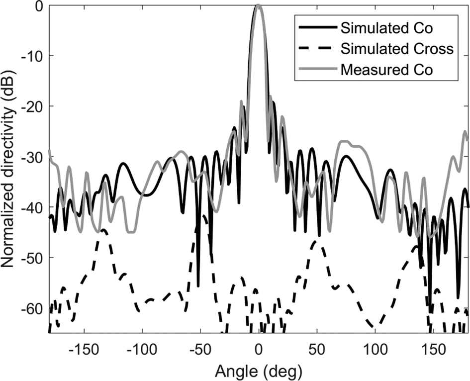
The measurement of the radiation patterns of the constructed antenna has been performed on an outdoor antenna test range. The simulated and the measured radiation patterns of the designed antenna in the E-plane are shown in Fig. 18. As seen from the figure, for the innermost side lobes, there is a slight difference between the simulated and measured radiation patterns. The measured levels of the innermost side lobes were approximately equal to −18 dB. Other simulated and measured side lobes are far below the prescribed side lobe level (i.e. −20 dB). The measured level of the back lobe is noticeable greater than the simulated level of the back lobe. This is most probably due to the reflections from the surrounding environment in the outdoor test range. The simulated cross-polarized level of the designed antenna is added to the figure. As the figure shows, the level of the cross-polarization at all angles is below −40 dB. The measured cross-polarization level was also below −30 dB with no noticeable variation against the azimuth angle because of the limited dynamic range of the employed detector in the measurement.
The radiation patterns of the designed antenna in the E-plane.

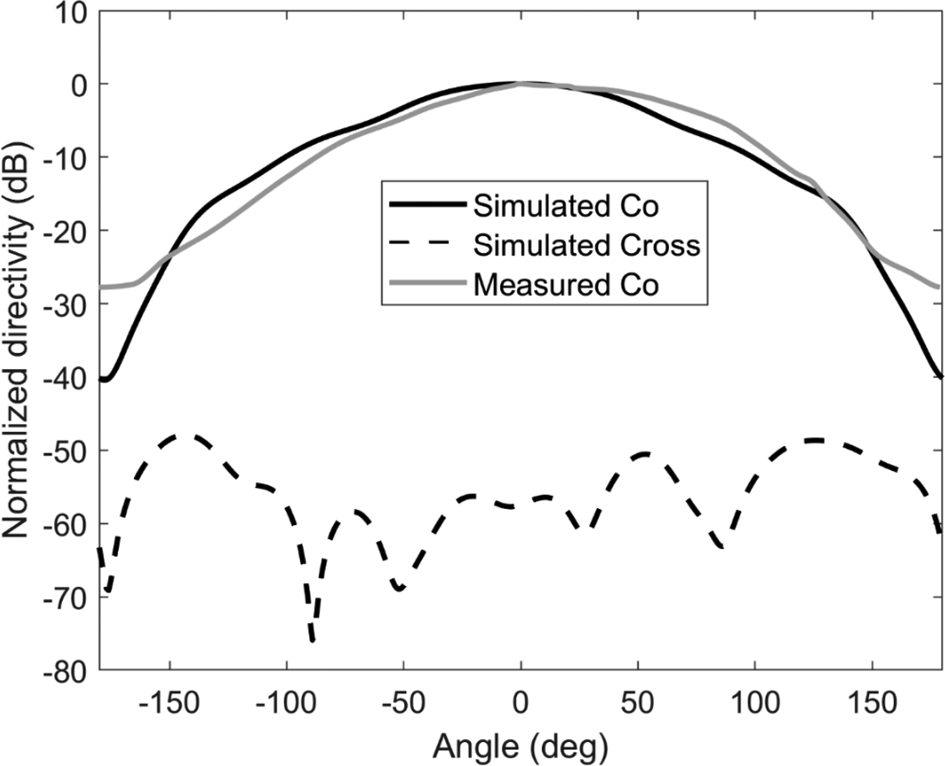
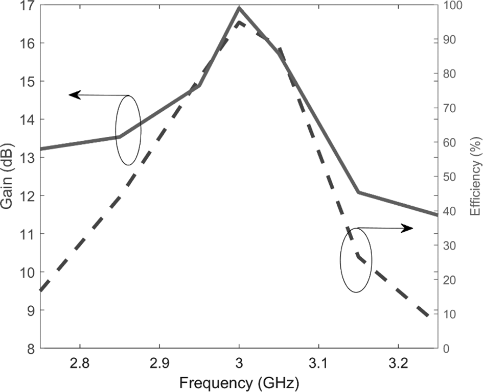
Figure 19 shows the simulated and measured radiation patterns of the designed antenna in the H-plane. As seen from the figure, the simulated radiation pattern is as expected symmetrical while the measured radiation pattern is slightly asymmetrical. As explained earlier, this is most probably due to the unavoidable reflection from the roughness of the ground surrounded by the antennas. The simulated cross-polarized level of the designed antenna is also added to the figure. As observed by the figure, it is approximately −40 dB below the co-polarization level at all directions. Similarly, the measured cross-polarization is −30 dB below the peak of the co-polarization component of the radiation pattern at all angles. Figure 20 shows the simulated gain and the radiation efficiency of the designed antenna. As the figure shows, the maximum gain is 16.9 dB at 3 GHz. The peak radiation efficiency is also 99% at 3 GHz. Both the antenna gain and the radiation efficiency decreased as the frequency deviated from 3 GHz. The measured gain of the designed antenna was approximately equal to 14.5 dB.
The radiation patterns of the designed antennas in the H-plane.

The gain and the radiation efficiency of the designed antennas versus frequency.

The simulated radiation patterns of the second designed array which is composed of the untilted edge slot antennas fed by the tilted wires in H- and E-planes have been derived. They were in good agreement with the simulated radiation patterns of the designed array composed of the proposed edge slot antennas. So, for preventing obscuration, they have not been added to Figs 18 and 19.
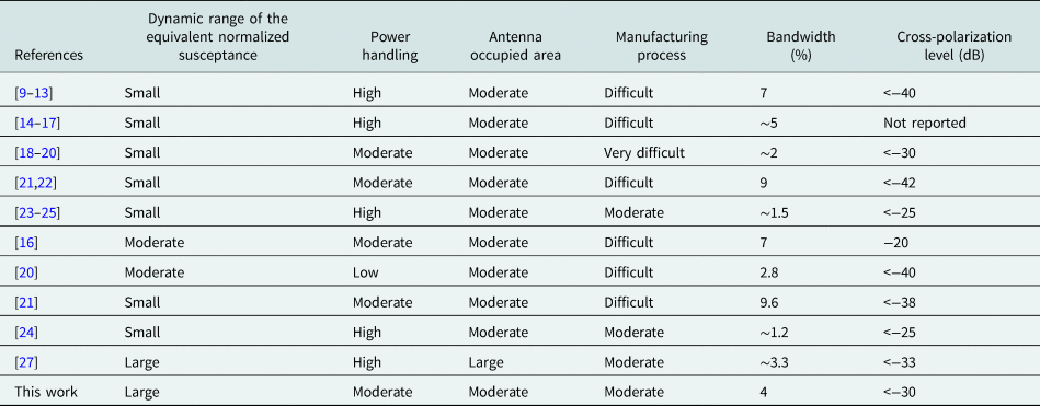
Table 4 compares different characteristics of the proposed antennas with the previously proposed antennas in the literature. According to the table, the proposed antennas demonstrate a large dynamic range of the equivalent normalized susceptance as well as moderate antenna occupied area. From the results, it can be concluded that the proposed edge slot antennas can be employed for designing different types of high-performance slotted array antennas.
Comparison between the characteristics of the proposed antennas and the previously proposed antennas.

Conclusion
The T-shaped wires were used as a replacement for tilted wires to excite the untilted edge slot antennas. For each untilted slot, two T-shaped wires are used to excite it. One arm of the T-shaped wires was connected to the narrow wall of the waveguide which contained the slots. The other arm of the T-shaped wires was connected to the upper or lower broad wall of the waveguides. The last arm of the T-shaped wires was unattached to the waveguides. It has been shown that the lengths of the unattached arms of the T-shaped wires can be used to control the susceptive part of the equivalent normalized admittance of the slots. The performed study has shown that the equivalent normalized admittance of the proposed edge slot antennas has a greater dynamic in comparison to the dynamic range of the untilted edge slot antennas fed by the tilted wires. Furthermore, a comparison of the performance of the designed arrays has revealed that the impedance matching as well as the frequency bandwidth of the array composed of the proposed slot antennas are greater than the array composed of the edge slot antennas fed by the tilted wires.
 Mahdi Moradian received the M.Sc. and Ph.D. degrees both in electrical engineering from the Iran University of Science and Technology, Tehran, Iran, in 2004 and 2011, respectively. Since his graduation, he has worked in several institutes and universities as a lecturer and research engineer. He is interested in different areas of science and engineering, but currently, his main focus is on the slotted waveguide array antennas.