I. INTRODUCTION
Ceramics with engineered porosity are required in a wide range of industries including energy, pharmaceutical, and manufacturing. While pore-free ceramics are sought after for improved optical, mechanical, and electrical performance, Reference Messing and Stevenson1 their porous counterparts are desired for their transport capabilities while providing high specific surface area, low thermal conductivity, and low relative density. Reference Colombo2 These characteristics are required for use in fuel cells, Reference Haberman and Young3 bone scaffolds, Reference Woodard, Hilldore, Lan, Park, Morgan, Eurell, Clark, Wheeler, Jamison and Wagoner Johnson4 and various filters and thermal management systems. Reference Heidenreich5 For these reasons, research in processing science and technology for porous ceramics has been steadily growing. Reference Okada, Isobe, Katsumata, Kameshima, Nakajima and MacKenzie6,Reference Ohji and Fukushima7
A key requirement for porous ceramics processing is the ability to tailor the pore network in accordance with the requirements of each application, specifically the pore size and shape, tortuosity, and connectivity. Reference Hammel, Ighodaro and Okoli8 To achieve control over these parameters, various processing techniques such as partial sintering, replication, direct foaming, and sacrificial templating have been exploited. Reference Studart, Gonzenbach, Tervoort and Gauckler9 In recent years, freeze casting (also called ice templating), a type of sacrificial templating, has attracted considerable interest. Reference Araki and Halloran10–Reference Seuba, Deville, Guizard and Stevenson15
In freeze casting, pore formation is based on phase segregation of a two-component system achieved via solidification. The process starts with a uniformly dispersed mixture consisting of a solid phase (e.g., alumina particles) and a liquid phase, typically water, which acts as the sacrificial template. As the temperature of the mixture is decreased, the liquid phase solidifies, rejecting the insoluble particles at the freezing front to form an array of crystals surrounded by “walls” comprised of solid particles. Once completely frozen, the sacrificial phase is removed through sublimation, thereby generating pores with a structure reminiscent of the solidified liquid phase. Pore structures, ranging from cellular to lamellar can be generated with this technique depending on the solidification conditions. Additionally, applied temperature gradients can result in directionally aligned pores with high aspect ratios, a feature which is difficult to achieve with other processing methods for porous solids.
Extensive studies have been performed on various processing parameters for freeze casting including particle size, Reference Deville, Saiz and Tomsia16,Reference Waschkies, Oberacker and Hoffmann17 particle shape, Reference Ghosh, Banda, Kang and Dhavale18 freezing front velocity, Reference Mullins and Sekerka19,Reference Miller, Xiao and Faber20 and solvent choice. Reference Chen, Wang, Huang, Ma and Lin21,Reference Han, Hong, Zhang, Du and Zhang22 Most of these studies have used colloidal suspension of ceramics and have examined the interaction of the suspended ceramic particles with the solidifying liquid phase. Phenomena such as particle engulfment and sedimentation have been taken into account as they can disturb the growth of ice crystals. Reference Chino and Dunand23 In contrast, single-phase solutions seldom have been used in freeze casting, a noted example being preceramic polymers. These polymers also have gained much interest as an alternative processing route for ceramic materials due to their versatility in forming techniques, lower synthesis temperatures than conventional powder processing, and new phase compositions exhibiting excellent high temperature properties. Reference Greil24–Reference Guo, Roso, Modesti, Liu and Colombo28
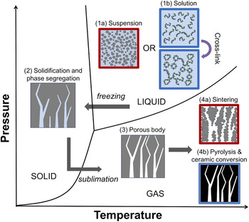
Freeze casting with preceramic polymers as a ceramic precursor inherently changes the processes involved during solidification, from segregation of a particulate suspension to solute rejection in a polymeric solution, as shown schematically in Fig. 1. The implications are significant. For example, the absence of suspended particles make many processing parameters studied in suspension freeze casting such as particle size and shape no longer relevant. Instead, new considerations arise in solution freeze casting, including issues such as polymer–solvent interactions and solvent compatibility.
Schematic of the freeze-casting process for both suspension- and solution-based systems. (1a) A stable suspension or a (1b) homogeneous polymer solution (followed by partial cross-linking) is first prepared. (2) The temperature is lowered, initiating solidification, and phase segregation. (3) Sublimation of the frozen solvent generates a porous body. (4a) Sintering or (4b) pyrolysis of the ceramic or polymer, respectively, is performed to obtain a robust porous ceramic.

Only a handful of studies have been performed on freeze casting of preceramic polymers and none has provided a direct comparison with traditional suspension freeze casting. First, Yoon et al. showed that SiC with dendritic pore structures can be made using polycarbosilane as the preceramic polymer and camphene as the solvent. Reference Yoon, Lee, Kim and Koh29 Studies by Naviroj et al. demonstrated that polysiloxane-derived SiOC with prismatic pores can be achieved with t-butanol as a solvent, while cyclohexane can also yield dendritic pores similar to camphene. Reference Naviroj, Miller, Colombo and Faber14 The latter can also show enhanced pore alignment by using a grain-selection technique, a process typically used for single-crystal turbine blades. Reference Naviroj, Wang, Johnson and Faber30 Zhang et al. recently created hierarchically porous structures through freeze casting partially pyrolyzed preceramic polymers. Reference Zhang, D’Angelo Nunes, Wilhelm and Rezwan31
In this work, suspension- and solution-based samples were freeze cast under equivalent conditions with the goal of establishing how pore structure is controlled by both process and casting medium. We chose four different organic solvents as casting media to provide a range of enthalpies of fusion. It has been shown that solidification microstructures can be correlated with the interfacial energy or Jackson α-factor, which is largely dependent on the material’s enthalpy of fusion. Reference Jackson, Uhlmann and Hunt32–Reference Jackson34 The α-factor provides an indication of whether crystal growth is considered atomically rough or smooth based on the lowest free energy configuration. This affects the solidification microstructure, its anisotropy, and consequently the pore structure generated. The following studies explore conditions for the range of pore structures achievable through freeze casting of alumina suspensions and solution freeze casting of polymethylsiloxane.
II. EXPERIMENTAL DETAILS
A. Suspensions
Ceramic suspensions were made by dispersing α-Al2O3 (HP-DBM, d 50 = 350 nm, Baikowski Inc., Malakoff, TX, USA) in cyclooctane, cyclohexane, dioxane, or dimethyl carbonate, listed here in the order of increasing enthalpy of fusion (Table I), at a solids loading of 15 vol% to target porosities of ∼70%. Al2O3 was chosen due to its wide use in freeze-casting studies and good compatibility with commercially available dispersants. Dispersants were added to each solvent at a concentration of 5 wt% (of solids). Hypermer KD-1 was used for dioxane and dimethyl carbonate while Hypermer KD-4 (Croda Inc., Edison, NJ, USA) was used for cyclooctane and cyclohexane based on the polarity of the solvents. Suspensions were then ball milled overnight to achieve a stable suspension prior to freeze casting.
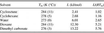
Melting temperature (T m), enthalpy of fusion (L), and calculated entropic term (L/(RT m)) for each solvent used, compared to water.

B. Solutions
Preceramic polymer solutions were made by dissolving polymethylsiloxane (CH3SiO1.5, Silres® MK Powder, Wacker Chemie, Munich, Germany) in cyclooctane, cyclohexane, dioxane, or dimethyl carbonate at a solids loading of 17 vol%, also to obtain porosities of ∼70%. An earlier study has shown that MK powder, a commercially available preceramic polymer, can be successfully used for freeze casting resulting in a high ceramic yield of roughly 75%. Reference Naviroj, Miller, Colombo and Faber14 After the polymer was fully dissolved, a cross-linking agent (N-(2-Aminoethyl)-3-aminopropyltrimethoxysilane, Geniosil® GF 91, Wacker Chemie, Munich, Germany) was added at a concentration of 1 wt% of the solution prior to freeze casting. Cross-linking was required for the polymer to retain its pore structure through the pyrolysis step. It should be noted that once the cross-linking agent is added to the polymer solution, cross-linking is initiated even at room temperature. While this can result in a gelled solution which does not freeze cast or sublimate properly, gelation usually requires several hours to occur and can easily be avoided. Following pyrolysis, a porous amorphous silicon oxycarbide (SiOC) ceramic was obtained.
C. Freeze casting
The freeze casting process for both systems was as follows: ceramic suspensions or polymer solutions at ambient temperature were poured into a glass mold with an inner diameter of 24 mm and a wall thickness of 4 mm. The glass mold was placed on top of a thermoelectric device which was cooled by a heat sink consisting of an aluminum plate connected to a circulating refrigerated silicone oil bath. A PID-controller was used to precisely set the temperature profile of the thermoelectric device. Since the freezing front velocity can affect the pore structure, the velocity was kept constant across all solvents, and as consistent as possible throughout the height of the samples.
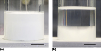
The freezing front velocity was measured using a camera and an intervalometer, followed by image analysis. While suspension-based samples were opaque, making observation of the freezing front difficult [Fig. 2(a)], polymer solutions were transparent prior to freezing and turn opaque when frozen, providing good visual contrast at the freezing front [Fig. 2(b)]. Consequently, solution-based samples were used to determine the temperature profiles required to obtain a constant freezing front velocity of 15 μm/s for each solvent. As each of the solvents have different freezing points, individualized temperature profiles were created for each solution. These temperature profiles were then used to solidify both solution- and suspension-based samples. Due to the freezing point depression caused by dissolved solutes in polymer-based samples, suspension-based samples are expected to experience a freezing front velocity that is slightly higher than the solution-based samples. However, these differences were neglected. Following freeze casting, samples were placed in a freeze dryer (VirTis AdVantage 2.0; SP Scientific, Warminster, PA, USA) until solvents were fully sublimated. Finally, Al2O3 samples were sintered in air at 1600 °C for 4 h, ramping at 5 °C/min, and polymer samples were pyrolyzed in argon at 1100 °C for 4 h, ramping at 2 °C/min to produce SiOC.
(a) Opaque suspension-based sample freeze cast with the freezing front not visible. (b) Transparent solution-based sample (cyclohexane) frozen halfway, showing a uniform freezing interface. Scale bars = 10 mm.

D. Characterization
Pore structures from both processing methods were observed using a scanning electron microscope (SEM; Zeiss 1550VP, Carl Zeiss AG, Oberkochen, Germany). Each sample was sectioned in both transverse (perpendicular to the freezing direction) and longitudinal (parallel to the freezing direction) orientations using a diamond saw. Transverse cross sections were obtained 5 mm from the bottom of each sample, with initial sample heights being roughly 20 mm. Longitudinal cross sections were obtained at the widest point in the cylinder cross-section. The pore size distribution and median pore size of each sample were characterized using mercury intrusion porosimetry (MIP; Auto Pore IV, Micromeritics, Norcross, GA, USA).
III. RESULTS
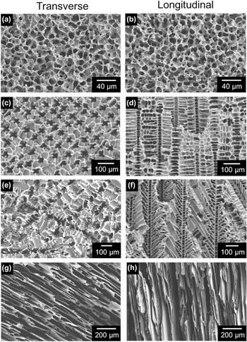
Figure 3 shows the pore structures obtained by freeze casting alumina suspensions with the four organic solvents, in both transverse and longitudinal directions. Cyclooctane suspensions produce a highly isotropic structure, with no differences between the transverse and longitudinal views [Figs. 3(a) and 3(b), respectively] despite the thermal gradient applied to achieve directional solidification. Cyclohexane suspensions [Figs. 3(c) and 3(d)] yield a similarly isotropic structure. Although there are some vertical features that can be seen in the longitudinal view due to directional solidification, they are relatively difficult to distinguish. With dioxane suspensions, dendritic features start to become discernible. Rows of dendrites are seen in the transverse view [Fig. 3(e)], while primary dendrites are seen growing upward in the longitudinal views [Fig. 3(f)]. Finally, dimethyl carbonate suspensions generate a lamellar structure as seen in Figs. 3(g) and 3(h). This lamellar structure is reminiscent of porous structures obtained via freeze casting of aqueous suspensions. The structure is also highly directional due to the temperature gradient applied during solidification.
Suspension-based freeze-cast pore structures prepared with (a, b) cyclooctane, (c, d) cyclohexane, (e, f) dioxane, and (g, h) dimethyl carbonate in both (a, c, e, g) transverse and (b, d, f, h) longitudinal views for ∼70% porosity Al2O3.

In comparison, Fig. 4 shows the pore structures obtained in SiOC by freeze casting preceramic polymer solutions. While cyclooctane solutions [Figs. 4(a) and 4(b)] produce a highly isotropic and foam-like structure very similar to its suspension counterpart, a drastic change in pore structure is observed in cyclohexane samples. With cyclohexane solutions, the transverse view [Fig. 4(c)] shows distinct dendrites having pinched secondary arms. The longitudinal view [Fig. 4(d)] shows pores generated by the secondary dendrite arms, as well as the structure’s high degree of anisotropy owing to the applied temperature gradient. Additionally, a considerable change in pore structure is also seen with dioxane solutions [Figs. 4(e) and 4(f)]. While the suspension-based samples did show some dendritic features and directionality, the dendrites seen in Fig. 4(f) show much greater directionality compared to those seen in Fig. 3(f). In contrast to cyclohexane where secondary dendrite arms grew orthogonal to the primary dendrites, dioxane’s secondary dendrite arms grow upward at an angle of approximately 45° with respect to the primary growth direction. Lastly, dimethyl carbonate solutions generated a lamellar structure [Figs. 4(g) and 4(h)] almost identical to its suspension-based counterpart. Overall, significant differences in pore structures are seen between suspension- and solution-based samples when cyclohexane and dioxane were used as solvents, with dendritic features emerging in the solution-based samples. In contrast, pore structures from cyclooctane and dimethyl carbonate samples exhibited little difference between the two systems.
Solution-based freeze-cast pore structures prepared with (a, b) cyclooctane, (c, d) cyclohexane, (e, f) dioxane, and (g, h) dimethyl carbonate in both (a, c, e, g) transverse and (b, d, f, h) longitudinal views for ∼70% porosity SiOC.

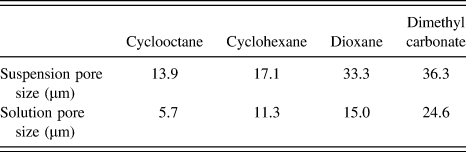
The median pore diameter for each sample was calculated from MIP and is listed in Table II. The results show that pore diameters increased from cyclooctane to dimethyl carbonate solvents, despite the same freezing front velocity of 15 μm/s. However, values for pore diameter obtained from MIP are calculated based on the throat size in which mercury is infiltrated when a certain pressure is applied. Since the throat of a spherical pore is inherently different from the lamellar spacing, noticeable differences in pore size are expected across solvents. This makes comparison of pore size across different types of structure a challenge. Pore size comparisons are best made when discussing analogous structures.
Median pore diameters obtained from mercury intrusion porosimetry for each type of sample.

Hence, comparing equivalent solvents between the two systems, results show that suspension-based samples yielded larger pore sizes than solution-based samples for all solvents used, ranging from 50% to more than twice as large. This change can be attributed to two factors: differences in the amount of undercooling during solidification and shrinkage during heat treatment. Solidification studies have shown that undercooling is a driving force for smaller microstructural features. Reference Nastac35 The presence of dissolved solutes (polymer) contributes to a larger degree of constitutional undercooling, and consequently smaller pore sizes are expected in solution-based samples. Additionally, the preceramic polymer experiences more shrinkage during pyrolysis than alumina does during sintering. This difference makes the median pore size of solution-based samples comparatively smaller than that of suspension-based samples.
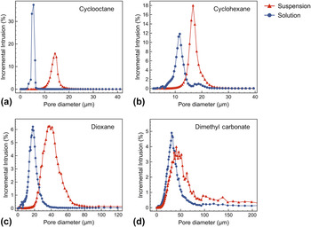
Pore size distributions for each solvent as determined by MIP, compared between suspension- and solution-based samples, are also shown in Fig. 5. For most solvents, the distribution profiles were quite comparable: unimodal pore size distributions with broader distributions in the case of suspension-based systems. One exception is cyclohexane [Fig. 5(b)]. While the cyclohexane suspension results in a unimodal pore distribution, its solution counterpart shows a bimodal pore size distribution. This can be attributed to the two types of pores generated by the primary dendrite and secondary dendrite arms, where the average size of the primary dendrite is greater that the secondary arm. Not surprisingly, the pore volume associated with the secondary dendrite is significantly larger, by about 15 times, than that of the primary dendrite since multiple secondary dendrites grow out from each primary dendrite. Interestingly, even though dioxane solutions also generated primary and secondary dendrite arms, as seen in Figs. 4(e) and 4(f), a bimodal pore size distribution is not detected by MIP. On closer examination, the two types of dioxane dendritic features are not significantly different in size.
Pore size distribution plots for (a) cyclooctane, (b) cyclohexane, (c) dioxane, and (d) dimethyl carbonate obtained from mercury intrusion porosimetry.

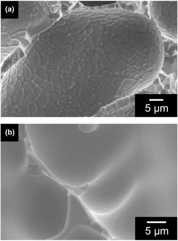
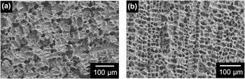
The pore wall surface morphology is also different between the two systems. Figure 6 shows the surface morphology of suspension- and solution-based samples. Figure 6(a) shows a rough surface with visible alumina grains obtained from sintering/coarsening, whereas Fig. 6(b) shows a very smooth SiOC surface. Homogeneous dissolution of a polymeric solution, along with the transformation of a preceramic polymer into an amorphous ceramic via pyrolysis, yields the glassy surface in contrast to the polycrystalline surface arising from suspension-based processing of ceramics.
Surface morphology of (a) sintered suspension-based alumina samples and (b) pyrolyzed solution-based preceramic polymer samples freeze cast with cyclohexane.

IV. DISCUSSION
A. Solidification microstructures
While solidification microstructures arise from the breakdown of planar growth due to instability of the solid–liquid interface, the features that form can also be attributed to the crystal structure of each material and its interfacial anisotropy. These factors influence the growth kinetics, and along with the externally applied growth conditions, determine the growth morphology. Reference Liu and Bennema36,Reference Haxhimali, Karma, Gonzales and Rappaz37 Although these generalizations may oversimplify the extremely complex solidification microstructures, one convenient method to correlate the interfacial anisotropy to the solidification microstructure is through the Jackson α-factor Reference Jackson34 :
 $$\alpha = {\eta \over Z}{L \over {k{T_{\rm{m}}}}}\quad ,$$
where η is the number of nearest neighbor sites adjacent to an atom on the interface, Z is the total number of nearest neighbors for an atom within the crystal, L is the enthalpy of fusion, k is the Boltzmann constant, and T m is the material’s melting temperature. It has been shown that low α values (<2) generally result in atomically rough growth interfaces and interfaces without facets, whereas at high α values, (>2) faceted growth is often observed. This α-factor expression can be partitioned into a crystallographic factor, η/Z, and an entropic factor, L/(kT m). While the crystallographic factor ranges between 0.25 and 1, the entropic factor can be calculated for each solvent to obtain a representative value for α, as shown in Table I.
The pore structures obtained from both suspension (Fig. 3) and solution (Fig. 4) systems show relatively good agreement with solidification structures expected based on the values in Table I. As the entropic factor increases, so too does the expected anisotropy, resulting in microstructures gradually changing from non-faceted to faceted.
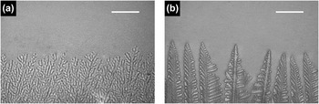
In the case of cyclooctane with the lowest entropic factor of 1.02, a very isotropic microstructure with no directional preference was obtained, despite the applied thermal gradient. Studies have shown that while dendritic structures are preferred at low interfacial anisotropies, an adequate amount of anisotropy is nonetheless required for their formation. Reference Kobayashi38 In cases where the anisotropy is particularly low, a more disordered seaweed structure is often formed. Reference Brener, Müller-Krumbhaar and Temkin39 As confirmation of this, various polymer solutions were solidified directionally under an optical microscope and images of the solidification microstructure were recorded. Figure 7 show a seaweed structure generated by a cyclooctane solution, while a classic directional dendritic structure is generated by dioxane. The isotropic pore structure obtained from cyclooctane, as viewed in cross-section, reflects the seaweed structure more accurately than that of a dendritic structure.
Optical micrographs showing solidification microstructures for preceramic polymer solutions with (a) cyclooctane and (b) dioxane as solvents. Cyclooctane’s low anisotropy generates a more disordered structure with low directionality while dixoane’s higher anisotropy generates directional dendrites. Scale bars = 150 µm.

The increased entropic factor for cyclohexane (1.16) correlates well with the dendritic structure formed. Similarly, dioxane’s entropic factor of 5.76 also corresponds to a dendritic structure. Minor differences exist, as dendrites from dioxane samples also have a tendency to form a linear, two-dimensional configuration similar to a lamellar structure, but in dendritic form [Figs. 3(e) and 4(e)]. It is possible that dioxane, with such a high entropic factor almost equal to dimethyl carbonate, begins to show signs of more faceted growth.
Dimethyl carbonate, notably with the highest entropic factor of 5.76, produced a lamellar structure representative of highly faceted crystal growth. The two-dimensional, high aspect ratio feature of a lamella is proof of the strong anisotropy, as growth is preferential in a particular direction and comparatively slow in the orthogonal direction.
While these results show good correlation with the Jackson α-factor, certain exceptions exist. For example, water is commonly used to create a faceted lamellar structure in suspension-based freeze casting despite having an entropic factor of only 2.65. Dioxane generates a dendritic structure, which is not faceted, while having a significantly higher entropic factor than water. This inconsistency demonstrates that the Jackson α-factor is not always an absolute measure of the magnitude of the solid–liquid interfacial energy, especially if the crystallographic factor is not known or taken into consideration. Nevertheless, the results obtained here, as well as in other sources, Reference Glicksman40 indicate that the α-factor is a reasonable guide to forecast the type of solidification microstructure that can be expected during freeze casting. It does not, however, explain the differences in pore structures obtained in suspension and solution castings.
B. Pore structure differences for suspension versus solution freeze casting
Pore structures derived from both cyclohexane and dioxane demonstrate notable differences depending on whether they were produced by suspension or solution freeze casting. It is hypothesized that this difference in pore structure is due to the presence or absence of suspended particles. Although it is possible that the addition of a solute such as the preceramic polymer to the solvent might influence the solidification microstructure, Reference Haxhimali, Karma, Gonzales and Rappaz37 Naviroj et al. Reference Naviroj, Miller, Colombo and Faber14 have shown that solute-free cyclohexane produces dendrites during solidification. Moreover, mixed suspension/solution samples were made with both alumina particles and dissolved preceramic polymer. Here, the preceramic polymer was first dissolved in the solvent, followed by addition of the dispersant and alumina. After ball milling, the cross-linking agent was added prior to freeze casting. These samples produced pore structures more similar to the suspension system (Fig. 8), providing further evidence that suspended particles are disrupting the dendritic solidification microstructure.
Pore structure for a mixed suspension/solution sample consisting of both alumina powder and preceramic polymer, with cyclohexane as a solvent. (a) Transverse view and (b) longitudinal view.

Brener et al. showed that a sufficient amount of noise ahead of a solid–liquid interface can affect the solidification microstructure by disrupting the growth of dendrite tips, destroying the regular patterns and instead creating fractal patterns. Reference Brener, Müller-Krumbhaar and Temkin39 This noise generally takes the form of fluctuations in the thermal or solute field ahead of the freezing front. Similarly, the presence of suspended particles located around the dendrite tips can act as a significant source of noise by inducing small temperature perturbations, as well as direct physical contact. In the present case, the noise generated by the alumina particles (∼350 nm) is approximately 1% the size of the each dendrite tip (∼40 μm). At this scale, we hypothesize that the dendrite tips are destabilized and break down, decreasing the anisotropy of the pore structure for cyclohexane and dioxane suspension-based samples.
In contrast, cyclooctane’s foam-like structure and dimethyl carbonate’s lamellar structure are interestingly retained regardless of processing routes. Recall that cyclooctane has the lowest entropic factor of all the solvents studies, associated with a correspondingly low anisotropy. Regardless of noise, stable dendritic growth cannot be achieved in either solutions or suspensions, and isotropic pore structures are therefore seen in both. As for dimethyl carbonate, since the stability of a growing interface is proportional to the interfacial anisotropy, the faceted lamellar structure is not affected by noise generated from the suspended particles. The structures are therefore also unchanged in both systems.
Results from various prior studies provide further evidence to support this explanation. Camphene, a non-faceted solvent, has been shown to create different structures in suspension- and solution-based systems, based upon independent studies. Suspension-based camphene produced a relatively isotropic structure, Reference Araki and Halloran10,Reference Han, Hong, Zhang, Du and Zhang22 however their solution-based counterparts created dendritic pore structures. Reference Naviroj, Miller, Colombo and Faber14,Reference Yoon, Lee, Kim and Koh29 Moreover, tert-butanol, a faceted solvent known to generate prismatic crystals, shows negligible difference between suspension- and solution-based samples, supporting the argument for dimethyl carbonate’s lamellar structure via both processing routes. Reference Naviroj, Miller, Colombo and Faber14,Reference Chen, Wang, Huang, Ma and Lin21
C. Technological implications of suspension versus solution freeze casting
Aside from the changes in pore structure, freeze casting of preceramic polymer solutions offers several processing advantages over traditional suspension freeze casting. With suspension-based samples, extensive care must be taken during colloidal processing to ensure that a stable suspension is obtained prior to solidification. This requires a dispersant or surfactant that is compatible with not only the desired solvent, but also the surface chemistry of the particles. Additionally, a time consuming ball-milling step is also required to break up agglomerates and prevent particles from settling. Alternatively, solution-based samples required comparatively little attention. Although a compatible solvent must be chosen such that the polymer can be dissolved, the dissolution process is completed over several minutes rather than hours.
The ability to observe the freezing front is also critical to the freeze-casting technique as it provides valuable information regarding the pore-formation process. While dispersed particles scatter light and cause suspensions to be opaque, solution-based samples are transparent and enable measurement of the freezing front velocity. Specifically, clear polymer solutions were seen ahead of the freezing front, implying that solid–liquid phase separation (polymer exsolution) was only occurring in conjunction with crystal growth, at the freezing point of each respective solution. However, under scenarios such as poor solvents or high polymer concentrations, cloudy solutions, indicative of phase separation in the liquid state due to limited solubility, were observed. Cloudy solutions could nevertheless be freeze cast normally, and showed no observable affect on the resulting microstructures. Moreover, although the solvents used in this study primarily showed a clearly defined freezing front due to their relatively low undercooling, other solvents, such as t-butanol and p-xylene, have been observed to solidify in a highly unstable manner due to their high degree of undercooling.
V. CONCLUSIONS AND OUTLOOK
This study provides the first direct comparison between suspension- and solution-based freeze casting as processing techniques for porous ceramics. Alumina powder and polymethylsiloxane preceramic polymer were each suspended or dissolved, respectively, in four different organic solvents and freeze cast to achieve various structures with ∼70% porosity. Differences in pore structures were largely seen in cyclohexane and dioxane samples, where distinct dendritic features were generated in solution-based samples but not in suspension-based samples. Mercury intrusion porosimetry showed that solution-based samples generated smaller pore sizes, with the cyclohexane sample creating a bimodal pore distribution due to the dendritic features.
The Jackson α-factor was used to correlate the pore structure with the various solvents used. Solvents with low entropic terms generated non-faceted structures whereas those with a larger value generated more faceted features, such as lamellae. Differences in structures generated from suspension- and solution-based processing were attributed to disturbances caused by presence of suspended particles. We suggest that the α-factor can be used as an approximate guide to predict the pore morphologies in new freeze-casting systems.
Various processing advantages gained with solution processing were also highlighted. Solution-based processing was shown to be the simpler processing technique with lower processing times. Additionally, transparent solutions allowed for direct observation during solidification, providing beneficial information for freeze casting. Innovative processing ideas based on polymer engineering can also be introduced to an inherently ceramics-based processing technique. Future studies can investigate the use of various polymer–solvent interactions or phase-separation mechanisms to create new structures or hierarchically porous ceramics.
This work has shown that freeze casting of preceramic polymer solutions is an appealing alternative to suspension-based freeze casting as a processing method for porous ceramics. Yet, while freeze casting of ceramic suspensions have been used to create porous materials for bone regeneration, Reference Mallick and Winnett41 solid oxide fuel cells, Reference Lichtner, Jauffrès, Roussel, Charlot, Martin and Bordia42 photocatalysis, Reference Xing, Zhou, Du, Qu, Tian, Pan, Tian and Fu43 and even drug delivery systems, Reference Szepes, Ulrich, Farkas, Kovács and Szabó-Révész44 polymer-derived freeze-cast ceramics have yet to be tested for use in any application. Fittingly, polymer-derived ceramics have shown to be promising materials for bioceramics, Reference Bernardo, Colombo, Cacciotti, Bianco, Bedini, Pecci, Pardun, Treccani and Rezwan45 battery anodes, Reference Graczyk-Zajac, Toma, Fasel and Riedel46 and catalysis. Reference Konegger, Williams and Bordia47 As all these applications also require tailored pore structures, freeze cast polymer-derived ceramics should be examined for improvements in performance.
ACKNOWLEDGMENTS
This work was supported by the National Science Foundation DMR-1411218 (MN and KTF) and NASA NNX16AR13G (PWV). The authors would like to thank Paolo Colombo for valuable discussions regarding preceramic polymers, as well as Noriaki Arai and Tai-Jung Kuo for assistance with optical microscopy.