


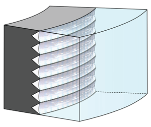



1. Introduction
Frictional drag reduction is of great significance in many engineering applications. Extensive research has been conducted on superhydrophobic (SHP) surfaces, because microstructures can capture air pockets underwater, creating a liquid–gas interface that functions as a slip boundary, leading to reduced drag in turbulent flows (Rothstein Reference Rothstein2010). Numerical simulations and experimental studies have been carried out to investigate drag reduction ( $DR$) of turbulent flow on SHP surfaces. The numerical results suggested consistently that SHP surfaces can achieve significant
 $DR$ in turbulence (Min & Kim Reference Min and Kim2004; Fukagata, Kasagi & Koumoutsakos Reference Fukagata, Kasagi and Koumoutsakos2006; Martell, Rothstein & Perot Reference Martell, Rothstein and Perot2010; Park, Park & Kim Reference Park, Park and Kim2013; Rastegari & Akhavan Reference Rastegari and Akhavan2015; Jung, Choi & Kim Reference Jung, Choi and Kim2016; Im & Lee Reference Im and Lee2017). Conversely, experimental results did not converge to any clear trend. Some studies reported that increasing the size and spacing of microstructures on SHP surfaces could result in greater
 $DR$ (Daniello, Waterhouse & Rothstein Reference Daniello, Waterhouse and Rothstein2009; Park, Sun & Kim Reference Park, Sun and Kim2014), while others showed little
 $DR$ or even drag increase when microstructure size increases (Gose et al. Reference Gose, Golovin, Boban, Mabry, Tuteja, Perlin and Ceccio2018). Notably, in turbulent Taylor–Couette (TC) flow, by using V-shaped grooves, Rosenberg et al. (Reference Rosenberg, Van Buren, Fu and Smits2016) demonstrated that varying Reynolds number (
 $Re$) has no significant impact on
 $DR$. In contrast, Van Buren & Smits (Reference Van Buren and Smits2017) obtained a maximum
 $DR$ of about 45 % in turbulent TC flow by varying
 $Re$ as well as the width of longitudinal rectangular grooves. Both Rosenberg et al. (Reference Rosenberg, Van Buren, Fu and Smits2016) and Van Buren & Smits (Reference Van Buren and Smits2017) noted that disruption of the plastron was observed during the experiment. Park, Choi & Kim (Reference Park, Choi and Kim2021) pointed out that the deterioration or depletion of the plastron is a significant reason for the inconsistency of
 $DR$ mechanisms in turbulent flows. The aforementioned studies indicate that further exploration is warranted regarding the effect of microstructure sizes on
 $DR$, particularly in cases involving stable air plastron.
The magnitude of  $DR$ depends not only on the geometry and size of the microstructure, but also on the
 $Re$ value of the base flow. Both direct numerical simulations and experiments suggest that the magnitude of
 $DR$ decreases with increasing
 $Re$ on the microstructure surface with a given geometry and size (in wall units) (Rastegari & Akhavan Reference Rastegari and Akhavan2018, Reference Rastegari and Akhavan2019). In contrast, other experimental studies have reported an enhancement of
 $DR$ with increasing
 $Re$ in turbulent boundary layer flows (Zhang et al. Reference Zhang, Tian, Yao, Hao and Jiang2015) or in turbulent TC flows (Srinivasan et al. Reference Srinivasan, Kleingartner, Gilbert, Cohen, Milne and McKinley2015; Rosenberg et al. Reference Rosenberg, Van Buren, Fu and Smits2016; Van Buren & Smits Reference Van Buren and Smits2017). Srinivasan et al. (Reference Srinivasan, Kleingartner, Gilbert, Cohen, Milne and McKinley2015) tested SHP surfaces with random roughness in TC flows and observed that the magnitude of
 $DR$ increased with increasing
 $Re$, achieving approximately
 $22\,\%$ at the highest
 $Re$ value tested. They derived a correlation between the dimensionless effective slip length (
 $b^{+}=b / \delta _\nu$) and the friction coefficient as well as
 $Re$, without focusing on the structural parameters. There is a complex multiscale interaction between the microstructural parameters and the flow parameter (
 $Re$) on the magnitude of
 $DR$, which needs to be explored further.
In turbulent flows, the drag reduction mechanism of SHP microstructures is usually attributed to the effective slip at the solid wall, which significantly influences the near-wall turbulence structures (Park et al. Reference Park, Choi and Kim2021). Research showed that the streamwise slip induced by microstructures in turbulent channel flow can inhibit near-wall turbulence structures by modifying the spanwise sweep and ejection dynamics of vortices (Park et al. Reference Park, Park and Kim2013; Jelly, Jung & Zaki Reference Jelly, Jung and Zaki2014). Conversely, spanwise slip has the potential to amplify streamwise turbulence structures and may even cause an overall increase in drag (Min & Kim Reference Min and Kim2004; Fukagata et al. Reference Fukagata, Kasagi and Koumoutsakos2006). Furthermore, investigations by Im & Lee (Reference Im and Lee2017) have explored the impact of alternating no-slip and slip boundary conditions on flow structures in turbulent pipe and channel flow, and found that increased spanwise slip can enhance secondary vortex structures, resulting in a higher  $DR$. Recent numerical and experimental studies by Jeganathan, Alba & Ostilla-Mónico (Reference Jeganathan, Alba and Ostilla-Mónico2021) and Jeganathan et al. (Reference Jeganathan, Shannak, Alba and Ostilla-Mónico2023) have also investigated the effects of alternative slip and no-slip boundary conditions on secondary flow and torque in turbulent TC flow, showing that the SHP treatment with appropriate axial spacing can effectively reduce the impact of vortices. While microstructural features and
 $Re$ significantly impact the effective slip (Srinivasan et al. Reference Srinivasan, Kleingartner, Gilbert, Cohen, Milne and McKinley2015; Rajappan et al. Reference Rajappan, Golovin, Tobelmann, Pillutla, Abhijeet, Choi, Tuteja and McKinley2019; Li et al. Reference Li, Ji, Tan, Li, Xiang, Lv and Duan2020a,Reference Li, Li, Tan, Wang, Huang, Xiang, Lv and Duanb; Ji et al. Reference Ji, Li, Du, Lv and Duan2023), the comprehensive analysis of the influence of variations in air-filled groove width and
 $Re$ on the slip boundary, thus affecting secondary flow and modulating
 $DR$ in turbulent shear flow, is lacking and warrants further exploration.
This study explores experimentally the effects of spacing width  $w$ and
 $Re$ on
 $DR$, and elucidates the underlying mechanisms. A theoretical model is also developed to describe the multiscale relationship between global response and geometrical and driving parameters.
2. Experimental facility
The TC facility is illustrated in figure 1(a). The inner cylinder with V-shaped microgrooves was manufactured using computer numerical control technology with precision approximately  $20\ {\mathrm {\mu }}{\rm m}$ and was mounted on the freely rotating spindle of the rheometer (DHR-2, TA Instruments, USA). The radii of the inner and outer cylinders are
 ${{r}_{i}}=25\pm 0.02$ mm and
 ${{r}_{o}}=35\pm 0.02$ mm, respectively, with the gap between the two cylinders
 $d={{r}_{o}}-{{r}_{i}}=10$ mm, corresponding to a radius ratio
 $\eta =r_i /r_o=0.714$. The height of the set-up is
 $L=84\pm 0.02$ mm, with aspect ratio
 $\varGamma =L/d=8.4$. Throughout the experiments, ultra-pure water was used as the working liquid, maintained at a constant temperature with precision
 $\pm 0.5\ \mathrm {K}$, which was achieved by a quartz glass cubic circulating bath surrounding the TC system (see figure 1a).
The experimental set-up. (a) Sketch of the experimental set-up including the TC facility. (b) PIV measurements in the  $r\unicode{x2013}\theta$ plane and
 $r\unicode{x2013}z$ plane.

To capture velocity in the  $r\unicode{x2013}\theta$ plane at mid-height
 $L/2$ and the
 $r\unicode{x2013}z$ plane, high-resolution particle image velocimetry (PIV) was employed. Fluorescent polymer tracer particles (Dantec FPP-RhB-10
 $1\unicode{x2013}20\ \mathrm {\mu }\mathrm {m}$) were added to the working fluid, and a laser sheet of thickness approximately 0.5 mm illuminated the tracer particles (see figure 1b). The camera lens was equipped with an Edmund High-Performance Long-pass 550 nm filter (910072, Beiting Measurement Technique, China) to optimize particle contrast. The velocity fields were captured with a high-resolution camera (Phantom v2640, USA) with
 $2048\times 1952$ pixels. The PIV images were post-processed in MATLAB's open-source PIVlab software (Thielicke & Sonntag Reference Thielicke and Sonntag2021) using multi-step interrogation windows ranging from
 $64\times 64$ to
 $16\times 16$ pixels. These fields were initially calculated in Cartesian coordinates and subsequently converted into polar coordinates.
To analyse the groove-induced  $DR$ effects, we fabricated the grooves with the shape of isosceles triangles and widths
 $w=600, 800, 1000, 1200\ \mathrm {\mu } {\rm m}$ (dimensionless form
 $\tilde {w}=w/d$) on the inner rotor. A layer of styrene ethylenebutylenestyrene copolymer chemical coating was applied, and subsequently SHP nanoparticles were sprayed (Cao et al. Reference Cao, Liu, Zhang, Wu, You, Li, Duan, Huang and Lv2024). Moreover, a hydrophilic treatment was performed on the tips of the V-grooves. The basic idea of hydrophilic treatment on the tips of grooves is to remove the SHP coating by direct polishing so that the hydrophilic substrate will be exposed, which involves two main steps. (i) We fabricate a hollow cylinder made of resin by three-dimensional printing. The inner surface of the hollow cylinder precisely matches the tips of grooves on the inner rotor. (ii) By the three-dimensional printed hollow cylinder covering and sliding on the inner rotor, the SHP coating on the tips of grooves is polished, thus the hydrophilic substrate underneath the SHP coating is exposed. Figure 2(a) displays a scanning electron micrograph of a hydrophilic-treated V-shaped groove, where the exposed groove tip can be observed.
Scanning electron microscopy of structured surfaces: (a) V-groove tips with hydrophilic treatment; (b) SHP surface; (c) hydrophilic-treated surface. The insets show the contact angle of a  $5\ \mathrm {\mu } {\rm L}$ ultra-pure water droplet over the corresponding surfaces.

To characterize the contact angle, tests have been conducted on flat surfaces. Figure 2(b) shows a scanning electron micrograph of the SHP surface with contact angle  $161^{\circ }$. We destroyed the SHP coating on the flat surface by using the same hydrophilic treatment to expose the hydrophilic substrate, on which the contact angle was reduced to
 $90^{\circ }$, as shown in figure 2(c). The hydrophilic treatment significantly alters the energy states of the SHP surface, particularly at the tips of the grooves. This alteration generates an energy barrier, restricts the movement of air, and strengthens the stability of the liquid–gas interface (see figures 3a,b). The width of each hydrophilic tip (
 $l_{tip}$) was measured to be
 $100\ \mathrm {\mu } \mathrm {m}$ using confocal microscopy (see figure 3c).
(a) V-shaped grooves in TC flow featuring a hydrophilic tip. (b) Two states of the liquid–gas interface in the V-groove with hydrophilic tips, at  $Re = 1.12\times {{10}^{4}}$ (on the left) and
 $Re = 4.21\times {{10}^{4}}$ (on the right). At
 $Re=4.21\times {{10}^{4}}$, the liquid–gas interface is depinned from the tips.(c) Confocal microscopy images of the hydrophilic tips of air-filled grooves.

Hydrophilic tips of V-grooves play an important role in pinning and stabilizing the liquid–gas interface, especially under highly turbulent flow. Experimental results showed that the liquid–gas interfaces in V-grooves with hydrophilic tips underwent two distinct states as the rotating speed increased, as shown in figure 3(b). Taking the microgroove width  $1200\ \mathrm {\mu } {\rm m}$ as an example, in the range
 $\omega _i < 40\ {\rm rad}\ {\rm s}^{-1}$, the liquid–gas interface remained stationary and stable; in the range
 $40<\omega _i<100\ {\rm rad}\ {\rm s}^{-1}$, the interface fluctuated but stayed pinned to the V-grooves. In contrast, the plastron in V-grooves without hydrophilic tips rises due to the buoyancy and pressure, resulting in uneven air distribution (see the supplementary movie available at https://doi.org/10.1017/jfm.2024.948). The experimental evidence for a robust air plastron is presented in Appendix B.
The torque of the inner rotor was measured using contactless sensors located in the rheometer head, while the outer cylinder remained stationary. For pure inner rotation,  $Re$ is defined with the gap width
 $d$ and the velocity of the inner cylinder
 $V_{i} = {{r}_{i}}{{\omega }_{i}}$ as
 \begin{equation} Re=\frac{r_{i}\omega_{i}d}{\nu}, \end{equation}
where  $\omega _{i}$ is the angular velocity of the inner cylinder, and
 $\nu$ is the kinematic viscosity. In the present work,
 ${{\omega }_{i}}$ ranged from 10 to
 $100\ {\rm rad}\ {\rm s}^{-1}$, resulting in
 $Re$ ranging from
 $2.7\times {{10}^{3}}$ to
 $2.79\times {{10}^{4}}$. The total torque of the TC system (
 ${{T}_{total}}$) was comprised of the torque exerted by the side wall of the inner rotor
 $T$ and the torque induced by the von Kármán flow at the end plates (
 ${{T}_{end}}$) (Greidanus, Delfos & Westerweel Reference Greidanus, Delfos and Westerweel2011; Hu et al. Reference Hu2017; Wang et al. Reference Wang, Yi, Jiang and Sun2022; Xu et al. Reference Xu, Li, Liu, Xiang, Lv, Tan, Zhao, Sun and Duan2023), and the isolation of
 $T$ from
 ${{T}_{total}}$ is detailed in Appendix A. For each experiment, the torque measurements were repeated five times, and the averaged value of
 $T$ was used, with the standard deviations below 2 %.
3. Results and discussion
3.1. Drag reduction
In this subsection, we experimentally examine the effects of varying microstructure size and driving strength on the global torque. The dimensionless wall shear stress is typically expressed using the skin friction coefficient, which is calculated from torque versus rotational speed data using the expressions
 \begin{equation} C_{f} =\frac{2\tau_{i}}{\rho V_{i}^{2} } =2\left( \frac{u_{\tau } }{V_{i}} \right)^{2}, \end{equation}
where  $\tau _{i} = T/(2{\rm \pi} r_i^2 L)$ is average inner wall shear stress, and
 $u_{\tau } = (\tau _{i}/\rho )^{1/2}$ is the friction velocity. Furthermore, the microstructure dimensions and driving strength can be characterized by the width of grooves
 $\tilde {w}$ and
 $Re$ based on the inner cylinder, respectively. The magnitude of drag reduction is denoted as
 $DR$ and calculated as
 $DR=1-{{C}_{f, w}}/{{C}_{f, smooth}}$.
The impacts of varying  $Re$ at different groove widths
 $\tilde {w}$ on the dimensionless wall shear stress
 ${C}_{f}$ are illustrated in figure 4(a), and the
 $DR$ in figure 4(b). Specifically, as the groove widens, the dimensionless wall shear stress
 ${C}_{f}$ declines, leading to a larger
 $DR$. Notably, a significant drag reduction has been observed in our experimental set-up, reaching 62 % at groove width
 $\tilde {w}=0.12$ and
 $Re=2.79\times {{10}^{4}}$. Moreover, figure 4(b) exhibits an uninterrupted increase of
 $DR$, in contrast to the existence of the decreasing trend observed in previous experimental studies (Rosenberg et al. Reference Rosenberg, Van Buren, Fu and Smits2016; Van Buren & Smits Reference Van Buren and Smits2017). The continuous growth of
 $DR$ indicates a more robust air layer captured in grooves over a wider range of
 $Re$ and
 $w$ in our research. Actually, the sustainable
 $DR$ at high
 $Re$, up to
 $Re=2.79\times {{10}^{4}}$, can be attributed to the hydrophilic treatment at the groove tips (see supplementary movie) to achieve a stable presence of the air layer.
(a) Plot of  ${{C}_{f}}$ as a function of
 $Re$, with various SHP groove widths
 $\tilde {w}$. (b) Drag reduction plotted against
 $Re$. In the plots, the predictions of the theoretical model (dashed lines) are very close to the experimental data (solid symbols), which proves that the theoretical model is highly accurate in predicting
 $C_f$ and
 $DR$ for different groove widths.

3.2. Angular momentum transport
To gain a deeper understanding of the drag reduction mechanism of air-filled grooves in TC flow, the angular velocity and flow organization are investigated with high-resolution PIV and the measurement methodology shown in figure 1(b). The angular velocity is measured at mid-height at  $Re=1.12\times {{10}^{4}}$ for each value of
 $\tilde {w}$. In TC flows, the angular velocity
 $\omega$, rather than the azimuthal velocity
 $u_\theta$, demonstrates the intrinsic property of transportation and exhibits an appropriate log law (Grossmann, Lohse & Sun Reference Grossmann, Lohse and Sun2016), with the slope
 $\lambda ^{-1}$ of the shear- and curvature-affected logarithmic region, as shown in figure 5(a). Here, the superscript ‘
 $+$’ denotes non-dimensionalization in terms of inner wall units, i.e.
 $y^+=(r-r_i)/\delta _\nu$ and
 $\omega ^+=(\omega _i-\omega )/(u_\tau /r_i)$, with
 $u_\tau$ and
 $\delta _\nu =\nu / u_\tau$. In figure 5(b), the profiles of diagnostic function
 $y^+\,{\rm d}\omega ^+/{{\rm d}y}^+$ not only collapse but also plateau at
 $1/ \lambda \approx 1/0.64$, consistent with the results of Berghout et al. (Reference Berghout, Verzicco, Stevens, Lohse and Chung2020, Reference Berghout, Bullee, Fuchs, Scharnowski, Kähler, Chung, Lohse and Huisman2021). Here, the Obukhov length
 $L_c= u_\tau /\kappa (\omega _i+\Delta \omega )$ is introduced to rescale the wall-normal distance to incorporate the curvature effect. Notably, as
 $\tilde {w}$ increases, the
 $\omega ^+$ profiles shift upwards by
 $\Delta \omega ^+$ (see figure 5a), indicating a reduction in drag and the presence of a finite slip length at the inner boundary, where the shift
 $\Delta \omega ^+$ is calculated by the intercept difference between the mean angular velocity profile
 $\omega ^{+}(y^{+})$ in the logarithmic region of the grooved surfaces and that of the smooth wall.
Angular velocity profiles based on the experiments with  $\omega _i=40\ {\rm rad}\ {\rm s}^{-1}$. (a) Mean angular velocity
 $\omega ^+$ as a function of
 $y^+$ for varying
 $\tilde {w}$. (b) Diagnostic function
 $y^+\,{\rm d}\omega ^+/{{\rm d}y}^+$, with wall-normal distance rescaled by Obukhov length
 $L_c$.

The slip boundary achieved by the grooved SHP surface can considerably reduce the angular velocity gradient  ${\partial }_{r}{\langle \omega \rangle }_{A,t}$ near the wall, and thus give rise to lower shear stress. The slip boundary affects the flow in the bulk region because of the conservation of the angular velocity current along the radius (Eckhardt, Grossmann & Lohse Reference Eckhardt, Grossmann and Lohse2007; Zhu et al. Reference Zhu, Ostilla-Mónico, Verzicco and Lohse2016). This effect manifests in the bulk region through changes in the characteristics of Taylor rolls, including their intensity and distribution. Taylor rolls, one of the typical secondary flows in a TC system, play a crucial role in the convective part of the angular velocity current along the radius (Brauckmann & Eckhardt Reference Brauckmann and Eckhardt2013; Ostilla-Mónico et al. Reference Ostilla-Mónico, Verzicco, Grossmann and Lohse2016). Figure 6 shows the distribution of the axisymmetric azimuthal vorticity
 ${\omega }_\theta = \partial u_r/\partial z - \partial u_z/\partial r$, and velocity vectors for air-filled grooves of varying
 $\tilde {w}$ in TC flow at
 $Re = 1.12 \times 10^4$, plotted in the
 $r\unicode{x2013}z$ plane. The intensity of the Taylor rolls for the smooth inner rotor is stronger than that of the air-filled grooves rotor, and their axial position varies slightly with
 $\tilde {w}$.
Radial–axial vorticity fields in the gap measured at  $Re=1.12\times {{10}^{4}}$. The axial position is normalized by the annular gap width.

The strength of Taylor rolls can be represented quantitatively by the wind Reynolds number, denoted as  ${Re}_{w}=\sigma (\langle {u_r}\rangle _t )\,d/\nu$, where
 $\sigma (\langle {u_r}\rangle _t )$ is the spatial standard deviation of the time-averaged radial velocity field
 $\langle u_{r}\rangle _t$ in the
 $r\unicode{x2013}z$ plane. Moreover,
 $\langle u_{r}\rangle _t$ values obtained in experiments at
 $Re = 1.12 \times 10^4$ are presented in Appendix C. The experimental results of
 ${Re}_{w}$ as a function of
 $Re$ at different
 $\tilde {w}$ are depicted in the inset of figure 7, which substantiates the theoretical proposition that
 ${Re}_{w} \propto Re^{6/7}$ (Grossmann & Lohse Reference Grossmann and Lohse2011; van der Veen et al. Reference van der Veen, Huisman, Merbold, Harlander, Egbers, Lohse and Sun2016). Meanwhile, figure 7 demonstrates that
 ${Re}_{w}$ of the air-filled grooves is lower than that of the smooth surface. Increasing the width of the grooves can further decrease
 ${Re}_{w}$, indicating a decrease in the intensity of the secondary flow. This reduction in secondary flow intensity consequently reduces the radial angular momentum transport, thereby increasing
 $DR$.
Wind Reynolds number  ${Re}_w$ compensated by
 $Re^{6/7}$ as a function of
 $\tilde {w}$, with the inset showing the original data of
 ${Re}_w$ varying with
 $Re$ at different
 $\tilde {w}$.

To sum up, the substantial and sustainable  $DR$ in § 3.1 corresponds to declined angular momentum transport and modified flow organizations, and can be attributed primarily to the considerable and stable slip length generated by the air-filled V-grooved surface featuring a hydrophilic tip.
3.3. Theoretical model
It has been suggested that drag reduction with air-filled microstructure surfaces depends not only on the geometrical parameters of the microstructure but also on the driving strength of the system (see figure 4), i.e.
 \begin{equation} {DR}={DR}(w,\phi_s, Re). \end{equation}
As suggested by Park et al. (Reference Park, Sun and Kim2014), we scale the groove width with the viscous length scale of the flow such that  $w^+ = w \nu ^{-1} \sqrt {\tau _i/\rho }$. In this subsection, an analytical expression of this relationship is presented based on angular momentum defect theory and magnitude estimate.
The derivation of (3.2) involves two steps due to the inherent multi-dimensionality of this problem. First, Srinivasan et al. (Reference Srinivasan, Kleingartner, Gilbert, Cohen, Milne and McKinley2015) proposed a modified skin friction law in turbulent TC flows ( $Re>Re_c \approx 14\,000$) which accounts for wall slip:
 \begin{equation} \sqrt{\frac{2}{C_f}}=M \ln \left(Re\,\sqrt{\frac{C_f}{2}}\right)+N+b^{+}, \end{equation}
where  $b^+=b{/\delta }_\nu =[b/(r_o-r_i)]\,Re\sqrt {C_f/2}$ represents the dimensionless effective slip length, the geometry-dependent constants
 $M=5.43$ and
 $N=-9.59$ are determined based on the no-slip case in our experimental set-up, and
 $C_{f}$ is the skin friction coefficient.
Equation (3.3) illustrates the correlation between macroscopic variables, namely  $DR=DR(b^+,{Re})$ or
 $C_f =C_f(b^+,{Re})$. Next, efforts have been made to bridge the gap between small-scale surface features and large-scale flow response. The latter is characterized primarily by the dimensionless slip length
 $b^+=b^+(w^+,\phi _s)$, where
 $\phi _s=l_{tip}/w$ denotes the solid fraction of the surface.
Drawing inspiration from the work of Rastegari & Akhavan (Reference Rastegari and Akhavan2019) on the  $DR$ scaling in the grooved SHP surfaces in turbulent channel flows,
 $b^+(w^+,\phi _s)$ is derived from magnitude estimates on the dynamics of turbulence kinetic energy (TKE) within the layer of thickness
 ${\sim }w$. Instead of the common primary term
 $-\langle {u_\theta u_r}\rangle \,\partial \langle {U}\rangle /\partial r$ in wall-bounded flows, it is the axial shear term
 $-\langle {u_\theta u_z}\rangle \,\partial \langle {U}\rangle /\partial z$ that dominates the overall production of TKE in the surface layer, which arises from significant axial gradient of azimuthal velocity due to the slip/no-slip patterns of the grooved surface. Rastegari & Akhavan (Reference Rastegari and Akhavan2019) demonstrate that the additional production of TKE through these axial shear layers is dissipated by the turbulent eddies above the no-slip regions, such that
 \begin{equation} \left \{ {-\langle {u_\theta u_{z}}\rangle\,\frac{\partial \langle {U}\rangle }{\partial z} } \right \} _{shear\ layer}\sim {\left \{ \upsilon \langle {s_{ij}s_{ij}}\rangle \right \}}_{no\ slip}. \end{equation}
On the left-hand side, utilizing the mixing length theory, the Reynolds stress  $-\langle {u_\theta u_z}\rangle$ is estimated as
 $-\langle {u_\theta u_z}\rangle \sim u^{\prime } l\,\partial \langle {U}\rangle / \partial z$, where the characteristic velocity of the largest eddies
 $u^{\prime }$ and their size
 $l$ are given by the geometric average of the corresponding scale at
 $r=0$ and
 $r \sim w$, specifically
 $u^{\prime } \sim \sqrt {u_{\tau n} u_\tau }=\sqrt {u_\tau / \sqrt {\phi _s}\,u_\tau }$ and
 $l \sim \sqrt {\delta _v \, w}$, while
 $\partial \langle {U}\rangle /\partial z$ is estimated as
 $U_{s s} /w$, where
 $U_{s s}=U_s /(1-\phi _s)$ is the average slip velocity of the microstructure walls. On the right-hand side, the fluctuating strain rate above the no-slip regions can be given by characteristic velocity dividing its associated inner length scale, i.e.
 $s_{i j} \sim u^{\prime } / \delta ^{\prime }$, where
 $\delta ^{\prime }=v / u^{\prime }$. Using the estimates above, the scaling is given as
 \begin{equation} U_s^{+}=b^+= K \left\{\left(1-\phi_s\right) \phi_s^{{-}3 / 8}\right\}\left\{w^{+}\right\}^{3/4}, \end{equation}
where the multiplicative coefficient  $K$ is determined to be 0.34 through linear regression. Here, the experimental results of
 $b^+$, or equivalently
 $U_s^+$ under the Navier slip hypothesis, is given by (3.3) based on torque measurement.
As indicated in (3.5), contributions of geometrical features to wall slip consist of two parts. On the one hand, the decrease in solid fraction  $\phi _s$ will give rise to reduced solid friction and thus enhanced slip. On the other hand, as the dimensionless groove width
 $\tilde {w}$ increases, the axial gradients of mean velocity and the TKE production in the shear layer decline, which also represents a larger wall slip.
Figure 8(a) presents the experimental results of  $b^+$ varying with
 $\tilde {w}$ and
 $Re$. The wall slip is enhanced with increasing
 $\tilde {w}$ and
 $Re$ within the investigated parameter space, aligning with the observed trend of
 $DR$ depicted in figure 4. Figure 8(b) shows
 $\{\phi _s^{3 / 8} /(1-\phi _s)\} b^+$ computed from these experimental databases, which can be seen to scale as
 $\{w^{+}\}^{3 / 4}$ in agreement with (3.5). We also explored the scaling dependence between the shift
 $\varDelta \omega ^+$ and
 $w^+$ as well as
 $\phi _s$, as shown in figures 9(a) and 9(b), and the multiplicative coefficient is determined to be 0.2 through linear regression.
(a) Plots of  $b^+$ as a function of
 $Re$ and
 $\tilde {w}$, where a solid symbol denotes experimental. (b) The logarithmic plot verifying the scaling of
 $b^+$, with the dashed lines showing the prediction of (3.5).

(a) Plots of  $\Delta \omega ^+$ as a function of
 $Re$ and
 $\tilde {w}$, where a solid symbol denotes experimental. (b) The logarithmic plot verifying the scaling of
 $\Delta \omega ^+$, with the dashed lines showing the prediction of the shift
 $\Delta \omega ^+$.

Accurate prediction of the friction coefficient  $C_f$ is essential when dealing with turbulent boundary layers affected by surface roughness. The joint equations (3.3) and (3.5) are effective in predicting
 $C_f$, i.e.
 \begin{equation} \sqrt{\frac{2}{C_f}}=M \ln \left(Re\,\sqrt{\frac{C_f}{2}}\right)+N + K \left\{\left(1-\phi_s\right) \phi_s^{{-}3 / 8}\right\}\left\{w^{+}\right\}^{3/4}. \end{equation}
Initially, (3.5) is used to determine  $b^{+}$ from the known values of
 $w^{+}$ and
 $\phi _s$. The calculated
 $b^{+}$ is then substituted into (3.3) to calculate
 $C_f$. This method requires only the parameters
 $w$,
 $\phi _s$ and
 $Re$ to predict the friction coefficient. As shown in figure 4, comparing the theoretical model with the experimental values shows that both the friction coefficient
 $C_f$ and
 $DR$ are predicted with high accuracy. The theoretical model can accurately predict friction and drag behaviour across surface roughness levels and flow conditions. In this way, theoretical models help engineers and researchers to understand complex multiscale interaction between the microstructural parameters (
 $w$ and
 $\phi _s$) and the flow parameter (
 $Re$) on the magnitude of
 $DR$, predicting complex flow phenomena that may be encountered in practical applications, providing a scientific basis for design optimization.
In terms of errors, the theory overpredicts  $b^{+}$ at large
 $w$ with high
 $Re$, and underpredicts it at lower
 $Re$. In the former cases, the plastrons over grooves undergo fluctuations and become challenging to maintain, leading to partial wetting and deterioration of the SHP surfaces, primarily adjacent to the hydrophilic tip of the grooves, as shown in figure 2(b). The partial deterioration of the plastron, or in other words, the depinning of the liquid–gas interface, will increase the solid fraction
 $\phi _s$. According to (3.5), as
 $\phi _s$ increases, the dimensionless slip of the surface declines, indicating the overestimate of
 $b^{+}$. Nevertheless, at lower
 $Re$, the underprediction of
 $b^{+}$ can be attributed to the curvature effect of the TC flow, which is more pronounced at finite
 $Re$ where the boundary layer is rather thick and curved (Berghout et al. Reference Berghout, Verzicco, Stevens, Lohse and Chung2020). Specifically, the curvature-induced TKE production (
 $P_{{curvature }}$) in the cylindrical coordinate should be taken into account in (3.4) (Berghout et al. Reference Berghout, Verzicco, Stevens, Lohse and Chung2020), i.e.
 \begin{equation} P_{{shear\ layer }}+P_{{curvature }}=\varepsilon_{{no\text{-}slip }}, \end{equation}
where  $P_{{curvature }}=(1/r)\langle u_\theta u_r\rangle \langle U\rangle =-u^{\prime } l (\langle U\rangle /r) (\partial \langle U\rangle /\partial r)>0$. This additional positive term will emerge on the left-hand side of (3.5) at finite
 $Re$ in TC flow, resulting in the overprediction of
 $b^{+}$ if the curvature effect is neglected. However, compared to the results from Van Buren & Smits (Reference Van Buren and Smits2017) where the optimum groove size before surface failure is
 $w^+\approx 35$, the counterpart in our experimental set-up can reach
 $w^+\approx 75$ or even higher due to the stabilization provided by hydrophilic tips of SHP grooves.
4. Conclusion
In this study, we incorporated hydrophilic tips in SHP grooves to enhance the stability of the plastron while retaining the appreciable drag reduction in TC flow at high  $Re$. Here,
 $DR$ with groove width
 $\tilde {w}=0.12$ reached 62 % at
 $Re=2.79\times {10^4}$. Based on torque and PIV measurements, the underlying mechanism of drag reduction was revealed. The air-filled grooves generated a significant wall slip, leading to a notable decrease in the intensity of Taylor rolls and angular momentum transport, consequently reducing drag. This phenomenon becomes more pronounced with increasing
 $\tilde {w}$. Moreover, a theoretical model was established based on angular momentum defect theory and magnitude estimate, in order to quantify the multiscale relationship between global response and geometrical and driving parameters. The surface solid fraction
 $\phi _s$ and the groove width with respect to inner scales
 $w^+$ turn out to be crucial to the friction drag. A decrease in the surface solid fraction can reduce wall shear, and an increase in the groove width can weaken turbulence kinetic energy production, rendering enhanced slip and drag reduction. Our work provides potential implications on the design and optimization of drag-reducing surfaces for enhancing efficiency and performance in various engineering applications, including transportation, marine engineering, and other relevant processes.
Supplementary movie
A supplementary movie is available at https://doi.org/10.1017/jfm.2024.948.
Funding
We are grateful for stimulating discussions with J. Wang and F. Xu, and for the support of the National Natural Science foundation of China (NSFC) under grant nos 12293000, 12293001, 11988102, 12172006, U2141251, 12202010, and Laoshan Laboratory (no. LSKJ202200500).
Declaration of interests
The authors report no conflict of interest.
Appendix A
In TC flow, the total system torque  $T_{{total }}$ can be decomposed into two parts: (i) the torque
 $T$ due to the shear stress on the wall of the inner rotor; (ii) the torque
 $T_{{end }}$ contributed by the von Kármán flow at the end plates. Considering the linear relationship between
 $T$ and the height of the inner cylinder (Greidanus et al. Reference Greidanus, Delfos and Westerweel2011; Hu et al. Reference Hu2017; Wang et al. Reference Wang, Yi, Jiang and Sun2022; Xu et al. Reference Xu, Li, Liu, Xiang, Lv, Tan, Zhao, Sun and Duan2023),
 $T_{{end }}$ can be determined from the vertical intercept of the fitting lines. We conducted torque measurement experiments with three different heights (
 ${L}, 1.5{L}, 2{L}$) of inner rotors, and the results are shown in figure 10. In these calibration experiments, the smooth case was used. The ratio of
 $T_{{end }}$ to
 $T_{{total}}$ is approximately constant (approximately
 $22\,\%$) at different
 $Re$.
The calibration of the torque measurements. The torque contribution from the von Kármán flow at the ends of the system can be determined as the vertical intercept of the fitting line.

Appendix B
In this study, we provide a supplementary movie comparing the evolution of the liquid–gas interface in V-grooves with and without hydrophilic tips. For  $Re=2.79\times 10^{4}$, the liquid–gas interface remains stable in V-grooves with hydrophilic tips, as shown in figure 11(a). In contrast, without hydrophilic tips, buoyancy and pressure cause the air to move upwards, leading to the degradation or disappearance of the air layer, as depicted in figure 11(b).
The comparison of the stability of liquid–gas interfaces at the groove tips with and without hydrophilic tips at  $Re=2.79\times 10^{4}$: (a) with hydrophilic tips; (b) without hydrophilic tips.

Appendix C
In this Appendix, we present experimental results of the time-averaged radial velocity  $\langle u_r\rangle _t$ in the
 $r\unicode{x2013}z$ plane, as shown in figure 12. It is evident that the size of rolls on the grooved surface is larger than that on the smooth surface, and the roll size increases as the groove width increases, which is consistent with the findings about the distribution of the Taylor roll in figure 6.
Temporally averaged radial velocity results  $\langle u_r\rangle _t$ from experiments at
 $Re = 1.12\times 10^4$.

Appendix D
We explore the relationship between  $C_f$ and
 $DR$ as a function of
 $w^+$ and
 $\phi _s$. As shown in figure 13, the data of
 $C_f$ and
 $DR$ from different
 $Re$ and
 $\tilde {w}$ are not fully collapsed, which suggests that the
 $Re$ effect still exists for
 $C_f$ and
 $DR$. Specifically, the
 $Re$ effect occurs in the logarithmic term of
 $C_f$ in (3.3), and in the
 $C_{f, smooth}$ term of
 $DR=1-C_{f, w} / C_{f, smooth}$. However, since the slip term
 $b^{+}=b / \delta _v=b /(r_o-r_i)\,{Re}\,\sqrt {C_f / 2}$ in (3.3) varies linearly with
 ${Re}\,\sqrt {C_f / 2}$, faster than the logarithmic term, the
 $Re$ effect tend to diminish at relatively high
 $Re$, resulting in a linear relationship between
 $\sqrt {2/ C_f }$ and
 $b^+$, as shown in figure 13(a).
The scaling of  $C_f$ and
 $DR$ with surface microtexture parameters (
 $w^+, \phi _s$) in turbulent TC flow from different
 $Re$ and
 $\tilde {w}$, with the dashed line showing the prediction for
 $C_f$.



