1. Introduction
The mandible is a vital component of oral and maxillofacial region, playing a pivotal role in maintaining facial contour, mastication, speech, swallowing, facial expressions, and other essential functions. Mandibular defects or deformities are common hard tissue defects, most of which are predominantly resultant from acquired factors [Reference Inchingolo, Patano, Piras, Ruvo, Ferrante, Noia, Dongiovanni, Palermo, Inchingolo, Inchingolo and Dipalma1, Reference Shao, Li, Fu, Meng, Zhu, Zhao, Huo, Xiao, Fan, Lin, Zhang and Yang2]. Mandibular deficiencies not only destroy the patient’s appearance but also lead to structural damage of the surrounding vital tissues and organs, severely impacting fundamental actions such as chewing and speaking. The psychological distress caused by facial disfigurement significantly affects patients’ social functioning, including interpersonal relationships and career choices [Reference Wolfaardt, Brecht, Taft and Grant3, Reference Troise, Arena, Barone, Raccampo, Salzano, Abbate, Bonavolontà, Romano, Sembronio, Robiony, Califano and Dell’Aversana Orabona4]. Consequently, mandible reconstruction should include two critical aspects: firstly, restoring the continuity of the mandible (contour reconstruction) to regain a natural facial form, and secondly, rehabilitating the occlusal relationship between the upper and lower jaws (functional reconstruction) to reinstate physiological functions like chewing and speaking. The dual objective of esthetics and functionality has very high requirements on the position and orientation accuracy of the bone segments, so as to achieve satisfactory reconstruction outcome [Reference Wu5, Reference Cheng, Carriere, Piwowarczyk, Aalto, Zemiti, de Boutray and Tavakoli6].
The anatomical structure of cranial-maxillofacial region is intricate, involving a maze of vital nerves and blood, relocation and orientation of bone segments, and so on. The surgical operation is dangerous and difficult, and many inexperienced doctors are discouraged [Reference Tolksdorf, Hohberger, Ernst, Tietz, Schultze-Mosgau and Tautenhahn7]. Conventional surgery relies heavily on the surgeon’s spatial stereo sense and experience to understand the intricate anatomical information and surgical plans. Intraoperatively, surgeons employ rulers for measurements and occlusal splints for graft positioning, leading to low accuracy. The surgeons need to continuously judge the surgical effect and improve the surgical plan based on the experience (Figure 1(a)), resulting in the surgical outcomes that are far from the ideal results [Reference Lin, Zhao, Han, Sun, Zhang, Kim, Yan, Chen, Aung, Liu, Wang, Li, Yang, Wang, Chai and Xu8]. The application of computer image processing and spatial navigation technologies have transformed craniofacial surgery through computer-aided surgical navigation system, which employs spatial localization technology to track surgical instruments in real-time during the operation, continuously updating and displaying the spatial relationship between the instruments and the patient within the surgical planning interface (Figure 1(b)) [Reference Balasundaram, Al-Hadad and Parmar9, Reference Lin, Shi, Tan, Bogari, Zhu, Xin, Xu, Zhang, Xie and Chai10]. The computer navigation guarantees the precise positioning of the graft and permits surgeons to precisely locate the osteotomy lines [Reference Alkhayatt, Alzahrani, Ahmed, Alotaibi, Alsaggaf, ALAlmuaysh and Alomair11, Reference Eugster, Merlet, Gerig, Cattin and Rauter12]. Thus, the computer-assisted surgery has transcended some limitations of traditional surgery, enhancing surgical outcomes to a notable degree [Reference Zhu, Deng, Liu, Wang, Guo and Guo13, Reference Lopukhov, Frolov, Solovyev, Prokhorenko, Mishchenkov, Klimov, Vorotnikov, Poduraev, Grin and Levchenko14].
The traditional surgery and computer-assisted surgery.

The computer-assisted navigation has brought a breakthrough improvement to the traditional mandibular reconstruction surgery; however, the spatial point localization is precise by the computer-assisted navigation, determining the precise orientation of spatial objects remains difficult for manual manipulation. It is very difficult to accurately position the bone by trembling and unstable manual operation, not to mention to achieve the desired spatial orientation accuracy. It is still difficult to precisely implement the preoperative surgical design with the computer-assisted navigation intraoperatively, leading to unsatisfied postoperative effect [Reference de Boutray, Cuau, Ohayon, Garrel, Poignet and Zemiti15, Reference Lin, Sun, Xu, Gao, Xu, Yang, He, Wang, Xie and Chai16]. Achieving the intraoperatively precise realization of the preoperative surgical plans is the key to enhance the outcomes of surgery [Reference Hu, Liu, Guo, Cao, Chen and Zhang17]. The oral and craniofacial surgery mainly involves bony structures, which have high stiffness and are not easily deformed, and the medical robot has high motion and positioning accuracy, good rigidity, and stability. Therefore, the robot-assisted operation of rigid materials is more accurate and stable than manual operation by doctors, and highly suitable for the mandibular reconstruction surgery [Reference Lei and Song18, Reference Nino and Carretero J.L.19]. This paper integrated medical robotic technology with computer-assisted navigation, constructing a robot-assisted navigation system for mandible reconstruction surgery. The system assisted surgeons to locate and manipulate the free ascending ramus bone segments and the fibular implant bone, achieving both accurate spatial positioning and orientation adjustments to ensure the precise implementation of the preoperative surgical design.
2. Robot-assisted navigation system for mandible reconstruction surgery
2.1. System overview
The robotic-assisted navigation system primarily encompasses a multi-arm robot, an optical localizer device, positioning brackets and probe, a measurement and control workstation, two haptic interaction devices, and a surgical design system, as illustrated in Figure 2.
The robotic-assisted navigation system for mandibular reconstruction surgery.

-
1. Multi-arm robot: It consists of three manipulators integrating active and passive degrees of freedom (DOFs) to position and hold the bone segments during surgery.
-
2. Optical localizer: It continuously tracks and locates the spatial positions and orientations of the positioning brackets and probes, transmitting the real-time information to the workstation.
-
3. Positioning bracket and probe: They establish coordinate systems based on the four reflective balls. The spatial location and attitude of the coordinate system were calculated based on the position of reflective balls, which can reflect infrared light emitted from the optical localizer.
-
4. Measurement and control workstation: It serves as the software running platform to control the robot, optical localizer, and force interaction devices with data calculation and exchange.
-
5. Force interaction device: It provides the haptic interaction for surgeons to simultaneously manipulate two manipulators with precise control by master-slave configuration.
-
6. Surgical design system: It implements preoperative surgical design and simulation, provides the ideal spatial position and orientation of bone segments, and displays the bone-to-patient relationships in real-time after spatial registration.
The safety precautions were proposed to avoid possible risk to patients, including software, electrical design, and mechanical means, besides the supervision of doctors. In software program, speed limit, position limit, and watchdog timer are applied. The response time limit is set in the communication handshaking procedure between robot controller and workstation. If any of them has not received response signal within the set time (50 ms) due to freeze-up, runaway, or other errors, the power will be shut off. In electrical design, the fuzes are implemented to limit current supplied to each servo motor. The hall position switch is attached to each active joint to limit position. In mechanical design, every servo motor is equipped with a brake, the active joints will be locked once losing power. Surgeons can stop the robot at any time by pressing the emergency stop button in case of emergency.
2.2. The structure design of robot
In mandibular reconstruction surgery, once the diseased segment of the mandible is removed, the surgical targets consist of the free ramus bone segments and the reconstructed implant graft. Under the influence of the attached muscle tension, the left and right free ramus segments will shift and rotate around their own joints, as shown in Figure 3. The robot needs to reposition and securely hold these free ramus segments according to the preoperative design, subsequently place the implant graft at the predesigned location. Finally, the surgeons use titanium plates and screws to join and fix the bone segments. Given that both the free bone segments and the graft are spatial rigid bodies with specific shapes and sizes, and the joint of the free ramus can be approximated as a spherical joint with three DOFs. Therefore, the manipulator requires at least six DOFs to achieve arbitrary spatial positioning and orientation adjustment of a rigid body.
The stress and displacement of free ramus bone.

Considering the operation demands of mandible reconstruction surgery, a mandible reconstruction robot equipped with three manipulators is designed. The dual lateral manipulators locate and hold the free ascending ramus segments on both sides, and the middle manipulator locates and clamps the fibula implant. Each manipulator necessitates six active DOFs to facilitate spatial positioning and attitude adjustments. To augment the manipulator’s range of motion and operational dexterity, an additional passive joint is incorporated between the wrist and the end-effector to simplify the connecting of the end-effector to the bone segments. Consequently, each manipulator consists of six active DOFs and one passive degree of freedom (DOF), as shown in Figure 4. The manipulator arm (joints 1–3) is configured in SCARA layout. The manipulator wrist (joint 4-6) adopts axes-intersecting structure of triple joints [Reference Gu and Ren20].
Structure design of multi-arm robot, joint 1–6: active joints, joint 7: passive joint.

2.3. Procedure of robot-assisted mandibular reconstruction surgery
The workflow for robot-assisted mandible reconstruction surgery is outlined in Figure 5 and includes the following stages [Reference Sun, Lin, Chen, Xu, Zin, Han and Chai21].
Procedure of robot-assisted mandibular reconstruction surgery.

-
1. Preoperative: The CT and MRI image data of the craniofacial area and fibula are scanned and imported into the surgical design system for three-dimensional (3D) model reconstruction. The surgeons design the operation plan, including virtual resection, implant design, and defect repair.
-
2. Intraoperative: The positioning brackets are installed after anesthesia. The spatial registration of the 3D model, the optical localizer, the patient, and the robot is completed using external markers. The diseased mandible section is removed, and the fibular graft is shaped with image-guided navigation. The robot’s left and right manipulators are controlled to grasp the bilateral free ascending bone segments. The robot’s middle manipulator clamps the transplanted fibula graft. The spatial relationship of the bone segments in the robot’s coordinate system is established. The manipulators are sequentially controlled to reach the target positions as designated preoperatively. Surgeons verify congruence with preoperative plans and may make adjustments. Finally, the surgeon secures the bone segments, disconnecting the manipulators.
-
3. Postoperative: The wounds are closed. The postoperative 3D model is reconstructed, which is compared with preoperative model to evaluate surgical outcomes.
3. Kinematics analysis of the mandibular reconstruction robot
3.1. Kinematics model of robot
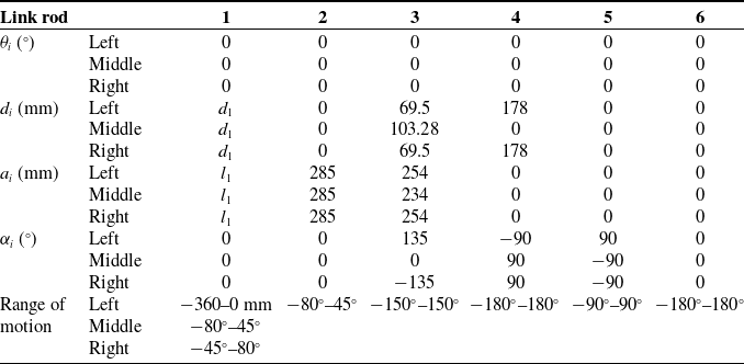
The kinematic models of each manipulator were constructed based on the Denavit-Hartenberg (D-H) method, as shown in Figure 6. The right arm is symmetrically structured and identical in dimensions to the left arm. The latter three coordinate systems of wrist joints converge at the spherical wrist’s center point [Reference Lei, Du, Song and Zhang22]. Consequently, the D-H parameters of each arm were derived accordingly in Table I.
The kinematic models of the left and middle manipulators.

Based on the link rod coordinate system in kinematic model, the homogeneous transformation matrix of adjacent linkage coordinate systems can be described by four homogeneous transformations, which represent the relative position of link i with respect to link i−1. The following equations are shortened with
 $\sin \theta _{i}=s\theta _{i} , \cos \theta _{i}=c\theta _{i} , \sin \theta _{1}=s_{1} , \cos \theta _{1}=c_{1} , \sin (\theta _{1}+\theta _{2})=s_{12} , \cos (\theta _{1}+\theta _{2})=c_{12}$
.
 \begin{align} {}^{i-1}{T}{_{i}^{}}=Rot\left(z,\theta _{i}\right)\textit{Trans}\left(0,0,d_{i}\right)\textit{Trans}\left(a_{i},0,0\right)Rot\left(x,\alpha _{i}\right)=\left[\begin{array}{c@{\quad}c@{\quad}c@{\quad}c} c\theta _{i} & -s\theta _{i}\times c\alpha _{i} & s\theta _{i}\times s\alpha _{i} & a_{i}\times c\theta _{i}\\ s\theta _{i} & c\theta _{i}\times c\alpha _{i} & -c\theta _{i}\times s\alpha _{i} & a_{i}\times s\theta _{i}\\ 0 & s\alpha _{i} & c\alpha _{i} & d_{i}\\ 0 & 0 & 0 & 1 \end{array}\right] \nonumber\\ \\ \nonumber\end{align}
The D–H parameters of the robot (i is the connecting rod number).

Given the middle manipulator as an example, the homogeneous transformation matrices of adjacent linkage coordinate systems can be calculated as:
 \begin{equation*} {}^{0}{T}{_{1}^{}}=\left[\begin{array}{c@{\quad}c@{\quad}c@{\quad}c} 1 & 0 & 0 & l_{1}\\ 0 & 1 & 0 & 0\\ 0 & 0 & 1 & d_{1}\\ 0 & 0 & 0 & 1 \end{array}\right] \quad {}^{1}{T}{_{2}^{}}=\left[\begin{array}{c@{\quad}c@{\quad}c@{\quad}c} c_{2} & -s_{2} & 0 & l_{2}\times c_{2}\\ s_{2} & c_{2} & 0 & l_{2}\times s_{2}\\ 0 & 0 & 1 & 0\\ 0 & 0 & 0 & 1 \end{array}\right] \quad {}^{2}{T}{_{3}^{}}=\left[\begin{array}{c@{\quad}c@{\quad}c@{\quad}c} c_{3} & -s_{3} & 0 & l_{3}\times c_{3}\\ s_{3} & c_{3} & 0 & l_{3}\times s_{3}\\ 0 & 0 & 1 & d_{3}\\ 0 & 0 & 0 & 1 \end{array}\right] \end{equation*}
 \begin{equation*} {}^{3}{T}{_{4}^{}}=\left[\begin{array}{c@{\quad}c@{\quad}c@{\quad}c} c_{4} & 0 & s{4}^{}{}{} & 0\\ s_{4} & 0 & -c_{4} & 0\\ 0 & 1 & 0 & 0\\ 0 & 0 & 0 & 1 \end{array}\right]\quad {}^{4}{T}{_{5}^{}}=\left[\begin{array}{c@{\quad}c@{\quad}c@{\quad}c} c_{5} & 0 & -s_{5} & 0\\ s_{5} & 0 & c_{5} & 0\\ 0 & -1 & 0 & 0\\ 0 & 0 & 0 & 1 \end{array}\right] \quad {}^{5}{T}{_{6}^{}}=\left[\begin{array}{c@{\quad}c@{\quad}c@{\quad}c} c_{6} & -s_{6} & 0 & 0\\ s_{6} & c_{6} & 0 & 0\\ 0 & 0 & 1 & 0\\ 0 & 0 & 0 & 1 \end{array}\right] \end{equation*}
Similarly, the homogeneous transformation matrices for the left and right manipulators can be calculated.
3.2. Forward kinematics solution
The forward kinematics represent the relationship between the joint variables and the end-effector’s position and orientation. For the middle arm, the position and orientation matrix of the end-effector can be obtained by sequentially multiplying the homogeneous transformation matrices of each link in section 3.1.
 \begin{equation} \begin{array}{l} {}^{0}{T}{_{6}^{}}={}^{0}{T}{_{1}^{}}\left(d_{1}\right){}^{1}{T}{_{2}^{}}\left(\theta _{2}\right){}^{2}{T}{_{3}^{}}\left(\theta _{3}\right){}^{3}{T}{_{4}^{}}\left(\theta _{4}\right){}^{4}{T}{_{5}^{}}\left(\theta _{5}\right){}^{5}{T}{_{6}^{}}\left(\theta _{6}\right)\\[6pt] \kern15.3pt=\left[\begin{array}{c@{\quad}c@{\quad}c@{\quad}c} c_{234}c_{5}c_{6}-s_{234}s_{6} & -c_{234}c_{5}s_{6}-s_{234}c_{6} & -c_{234}s_{5} & l_{1}+l_{2}c_{2}+l_{3}c_{23}\\ s_{234}c_{5}c_{6}+c_{234}s_{6} & -s_{234}c_{5}s_{6}+c_{234}c_{6} & -s_{234}s_{5} & l_{2}s_{2}+l_{3}s_{23}\\ s_{5}c_{6} & -s_{5}s_{6} & c_{5} & d_{1}+d_{3}\\ 0 & 0 & 0 & 1 \end{array}\right] \end{array} \end{equation}
Similarly, the forward kinematics of the left and right manipulators can be determined. Let
 $d_{1}=d_{1} , \theta_2=0, \theta_3=0, \theta_4=0, \theta_5=0, \theta_6=0,$
. The forward kinematic solution
 ${}^{0}{T}{_{6}^{}}$
of the middle manipulator is consistent with the coordinate system (6) in the kinematic model in Figure 6.
3.3. Inverse kinematics solution
When the position and orientation of the robot’s end-effector are known as Eq. (3), inverse kinematics is the process of solving for each joint angle value corresponding to the position and orientation. Taking the inverse kinematics solution of the middle manipulator as an example, substitute Eq. (2) into Eq. (3).
 \begin{equation} {}^{0}{T}{_{6}^{}}={}^{base}{T}{_{end-\textit{effector}}^{}}=\left[\begin{array}{c@{\quad}c@{\quad}c@{\quad}c} n_{x} & o_{x} & a_{x} & p_{x}\\ n_{y} & o_{y} & a_{y} & p_{y}\\ n_{z} & o_{z} & a_{z} & p_{z}\\ 0 & 0 & 0 & 1 \end{array}\right] \end{equation}
-
1. Solving
 $d_{1}$
of joint 1: The Eq. (3) is transformed as
${}^{0}{T}_{1}^{-1}(d_{1}){}^{0}{T}{_{6}^{}}={}^{1}{T}{_{2}^{}}{}^{2}{T}{_{3}^{}}{}^{3}{T}{_{4}^{}}{}^{4}{T}{_{5}^{}}{}^{5}{T}{_{6}^{}}={}^{1}{T}{_{6}^{}}$
, then
$d_{1}$
is solved as
$d_{1}=p_{z}-d_{3}$
.
-
2. Solving
$\theta _{2}$
of joint 2: The Eq. (3) is transformed as
${}^{1}{T}{_{2}}^{-1}(\theta _{2}){}^{0}{T}{_{1}}^{-1}(d_{1}){}^{0}{T}{_{6}^{}}={}^{2}{T}{_{3}^{}}{}^{3}{T}{_{4}^{}}{}^{4}{T}{_{5}^{}}{}^{5}{T}{_{6}^{}}={}^{2}{T}{_{6}^{}}$
, then
$\theta _{2}$
and
$\theta _{3}$
are solved as,


 \begin{align*} \theta _{2}&=\pm \arctan \left(\frac{a^{2}+b^{2}-c^{2}+{l_{2}}^{2}}{\sqrt{4{l_{2}}^{2}\left(a^{2}+b^{2}\right)-\left(a^{2}+b^{2}-c^{2}+{l_{2}}^{2}\right)^{2}}}\right)+\alpha\\[6pt] \theta _{3}&=2\arctan \left(\pm \sqrt{\frac{2l_{2}c-a^{2}-b^{2}+c^{2}+{l_{2}}^{2}}{2l_{2}c+a^{2}+b^{2}-c^{2}-{l_{2}}^{2}}}\right)\\[-6pt]\end{align*}
where
 $p_{y}=a , l_{1}-p_{x}=b , l_{3}=c , \tan \alpha =b/a$
.
Using a similar method, the
 $\theta _{4} , \theta _{5}$
and
 $\theta _{6}$
are solved as,
 \begin{align*} \theta _{4}=\arctan \left(\frac{-a_{x}s_{23}+a_{y}c_{23}}{a_{x}c_{23}+a_{y}s_{23}}\right) \quad \theta _{5}=\arctan \left(\frac{n_{z}}{n_{x}c_{234}+n_{y}s_{234}}\right) \quad \theta _{6}=\arctan \left(\frac{n_{x}s_{234}-n_{y}c_{234}}{o_{x}s_{234}-o_{y}c_{234}}\right)\\[-6pt] \end{align*}
Similarly, the inverse kinematics results of the left and right manipulators can be solved.
4. Spatial registration of robot-assisted surgery
In traditional spatial registration based on point cloud matching, the correspondence between points in two sets is unknown, requiring iterative computations of algorithm to find the optimal transformation matrix. However, in mandible reconstruction surgery, the correspondence between points in the two sets is predefined. An Improved Iterative Closest Point (ICP) algorithm takes this known correspondence as an initial condition to avoid the iterative solving process of classic ICP. Least square method is then employed to determine the mapping relationship between point sets, the result error of which is utilized to iteratively calculate the transformation matrix until the error falls below a threshold (±0.01 mm in the paper). The robot-assisted system decomposes four spaces, including 3D-image space
 $V$
, patient space
 $P$
, robot space
 $R$
, and optical measurement space
 $O$
, as shown in Figure 7.
Spatial decomposition and coordinate system construction.

Within the preoperative surgical design system, the 3D model of patient is reconstructed to establish the 3D-image space coordinate system
 $C_{V}$
. The patient space coordinate system
 $C_{P}$
is established by the positioning bracket installed on patient’s head, while the robot space coordinate system
 $C_{R}$
is established by the positioning bracket installed on the robot’s body. The optical localizer inherently possesses its own optical measurement space coordinate system
 $C_{O}$
, which is the reference of the positions and orientations of both the positioning bracket and probe. Due to the undeterminable relative position between the robot’s positioning bracket and its mechanical noumenon, this paper introduces three known-size markers machined onto the robot’s mechanical noumenon. By employing these three points, the robot local coordinate system
 $C_{r}$
is established, thereby creating the robot local space
 $U$
. The relationship between
 $O$
and
 $U$
is determined through the positioning probe measured by the optical localizer [Reference Kwon, Kim and Hwang23]. Given the established relationship between
 $O$
and
 $R$
, the relationship between
 $U$
and
 $R$
can consequently be determined. Referring to Figure 7, with three known points
 $A , B$
, and
 $C$
, vector
 $\overset{\rightarrow }{AB}$
defines the
 $X$
-axis, with its unit vector denoted as
 $\overset{\rightarrow }{x}$
. The
 $Y$
-axis is defined by the vector
 $\overset{\rightarrow }{AC}\times \overset{\rightarrow }{AB}$
, with its unit vector denoted as
 $\overset{\rightarrow }{y}$
. Lastly, the
 $Z$
-axis is defined by the vector
 $\overset{\rightarrow }{x}\times \overset{\rightarrow }{y}$
, with its unit vector denoted as
 $\overset{\rightarrow }{z}$
.
4.1. Spatial registration based on the improved ICP
Spatial registration is essential to solve the mapping relationship (transformation matrix) between coordinate systems to determine the relative spatial relationship between the robot’s end-effector and the 3D model of the surgical design system, so that the designed target position and orientation are translated from the 3D-image space to the robot space. The robot is finally controlled according to the surgical design.
-
(1) Registration of patient space and optical measurement space
Based on the measurement of the patient’s positioning bracket, the optical localizer directly provides the position and orientation
$C_{P}$
relative to
$C_{O}$
, expressed in the form of quaternions. Then the homogeneous transformation matrix
${}^{O}{T}{_{P}^{}}$
between space
$P$
and space
$O$
is determined, effectively accomplishing the registration between the patient space and the optical measurement space. -
(2) Registration of patient space and 3D-image space based on improved ICP
As illustrated in Figure 8, the titanium screw landmarks pre-implanted in the patient serve as registration points. Using the positioning probe, the coordinate values of these landmarks under
$C_{O}$
are sequentially acquired to form a point set
$\overset{\rightarrow }{q}$
, which is transformed into point set
$\overset{\rightarrow }{h}$
under
$C_{P}$
according to
${}^{O}{T}{_{P}^{}}$
. Simultaneously, using the surgical design system, the coordinate values of the corresponding landmarks on the 3D model are obtained under
$C_{V}$
in the same order to form a point set
$\overset{\rightarrow }{p}$
. Employing the improved ICP algorithm, the transformation matrix
${}^{V}{T}{_{P}^{}}$
between point sets (
$\overset{\rightarrow }{p} , \overset{\rightarrow }{h}$
) can be calculated, to accomplish the spatial registration between the patient space and the 3D-image space.Figure 8.The mark point acquisition for spatial registration.
-
(3) Registration of 3D-image space and optical measurement space
The coordinate transformation between the 3D-image space and the optical measurement space is solved by computing the homogeneous transformation matrix
${}^{O}{T}{_{V}^{}}={}^{O}{T}{_{P}^{}}{}^{P}{T}{_{V}^{}}={}^{O}{T}{_{P}^{}}({}^{V}{T}{_{P}^{}})^{-1}$
between space
$V$
and space
$O$
. -
(4) Registration of optical measurement space and robot (local) space
The position and orientation of the robot’s position bracket is directly measured under
$C_{O}$
to determine the homogeneous transformation matrix
${}^{O}{T}{_{R}^{}}$
between space
$R$
and space
$O$
, which completes the registration between the optical measurement space and the robot space. However, the position relationship between the robot’s positioning bracket and the robot’s mechanism body (i.e., the base coordinate system of the manipulator) is uncertain due to the manual installation with screws, as depicted in Figure 8. In addition, the kinematic solution and motion control of the robot are conducted within the manipulator space (denoted as
$M$
), taking the first link’s coordinate system as the base coordinate system
$C_{m}$
of the manipulator space, as shown in Figure 6. Hence, it is necessary to solve the transformation matrix
${}^{M}{T}{_{O}^{}}$
between
$C_{O}$
and
$C_{m}$
. As shown in Figure 8, the dimensions and positions of the markers machined onto the robot itself are known, thus the relative position relationship between
$C_{r}$
and
$C_{m}$
is established to obtain the homogeneous transformation matrix
${}^{M}{T}{_{U}^{}}$
between space
$U$
and
$M$
. Through the positioning probe, the position and orientation of
$C_{r}$
under
$C_{O}$
can be acquired to determine the homogeneous transformation matrix
${}^{M}{T}{_{O}^{}}={}^{M}{T}{_{U}^{}}({}^{O}{T}{_{U}^{}})^{-1}{}^{O}{T}{_{U}^{}}$
between space
$U$
and
$O$
, which completes the registration between the optical measurement space and the robot local space. The registration between the optical measurement space and the manipulator space is solved by calculating
${}^{M}{T}{_{O}^{}}={}^{M}{T}{_{U}^{}}({}^{O}{T}{_{U}^{}})^{-1}$
. Subsequently, the registration between the robot space and the manipulator space is solved by calculating
${}^{M}{T}{_{R}^{}}={}^{M}{T}{_{O}^{}}{}^{O}{T}{_{R}^{}}$
-
(5) Registration of robot space and patient space
The registration between the robot space and patient space is accomplished by solving the homogeneous transformation matrix
${}^{R}{T}{_{P}^{}}={}^{R}{T}{_{O}^{}}{}^{O}{T}{_{P}^{}}$
between space
$P$
and space
$R$
. -
(6) Registration of 3D-image space and robot space
The registration between the 3D-image space and the robot space is accomplished by solving the homogeneous transformation matrix
${}^{R}{T}{_{V}^{}}={}^{R}{T}{_{O}^{}}{}^{O}{T}{_{P}^{}}({}^{V}{T}{_{P}^{}})^{-1}$
between space
$V$
and space
$R$
. Similarly, the registration between the 3D-image space and the manipulator space is accomplished by solving the homogeneous transformation matrix
${}^{M}{T}{_{V}^{}}={}^{M}{T}{_{R}^{}}{}^{R}{T}{_{V}^{}}$
between space
$V$
and space
$M$
. During the surgical procedure, the bone segments are gripped by the manipulators. The optical localizer measures the bone segment’s current position and orientation in the robot space, which is then transformed into the manipulator space. Concurrently, the ideal target position and orientation of the bone segments, as designed preoperatively in the 3D-image space, are also transformed into the manipulator space. Based on both the current and ideal position and orientation of bone segments, the inverse kinematics of the manipulators are solved. Then the joints of the manipulators are controlled to move and hold the bone segments, in order to accurately implement the preoperative surgical design intraoperatively.


4.2. Hand-eye registration for multi-arm robot
After spatial registration between the robot coordinate system
 $C_{r}$
and the optical measurement coordinate system
 $C_{O}$
, it is necessary to further determine the relationship between the end-effector (hand) of the manipulator and the optical localizer (eye). During surgery, the optical localizer dynamically locates and tracks the end-effector in real-time. The difference between the target position and the current position of the end-effector is continuously calculated and updated to control the manipulator. This process is known as hand-eye registration in robot-assisted surgery [Reference Meng, Li, Yuan, Wu and Shen24, Reference Han, Tian, Vercauteren, Liu, Li and Duan25].
The traditional hand-eye registration method of multi-arm robot directly installs the positioning bracket on each manipulator’s end-effector, the position and orientation of which is obtained by the optical localizer in the optical measurement space. However, when the number of manipulators increases, combined with the limited workspace, there is a high likelihood of mutual occlusion of the positioning brackets among manipulators. In this paper, an optimized hand-eye registration method for a three-arm robot is proposed by integrating the optical localizer and robotic kinematic analysis. As shown in Figure 7, the positioning bracket is installed on the robot mechanism body, thereby constructing the robot space coordinate system
 $C_{R}$
. Firstly, the position and orientation of the end-effector in the base coordinate system
 $C_{m}$
of the manipulator is solved based on the robotic kinematic analysis described in section 3.2. Then, combining the transformation relationships between
 $C_{m}$
and
 $C_{R} , C_{R}$
and
 $C_{O}$
discussed in section 4.1, the position and orientation of the end-effector is ultimately transformed from the coordinate system
 $C_{m}$
to
 $C_{O}$
. In this method, the three manipulators do not block the positioning bracket on the robotic mechanism body, avoiding the occlusion issue of the traditional method and enhancing the practical applicability.
The spatial registration of free bone blocks.

4.3. Spatial registration of free bone blocks
In the surgery, the implant bone block is free outside the surgical area, the left and right ramus bone blocks are free in the patient’s space due to muscular forces, losing the positional relationship with the patient coordinate system. The size of the free bone blocks is too small to install the positioning bracket, which will affect the surgical operation and is easily blocked for optical measurement. In this paper, titanium screws are embedded in the free bone blocks as markers. The method illustrated in Figure 7 is employed to establish a local coordinate system specific to the bone block using markers. By utilizing the results of spatial registration, the position and orientation of the free bone blocks are calculated.
Firstly, the free bone block is connected with the end-effector of the manipulator, as shown in Figure 9. The markers on the block are sequentially selected by the positioning probe to acquire their coordinate values in coordinate system
 $C_{O}$
, which establishes the entity-based coordinate system
 $C_{B}$
of the free bone block. The initial position and orientation matrix of
 $C_{B}$
relative to
 $C_{O}$
can be calculated as
 $K_{O}$
, which can be ulteriorly translated in the manipulator space
 $M$
to obtain the initial position and orientation matrix of
 $C_{B}$
by
 $K_{M}={}^{M}{T}{_{R}^{}}{}^{R}{T}{_{P}^{}}K_{O}$
, incorporating the transformations detailed in section 4.1. Secondly, in the 3D-image space, the same markers are selected following the same sequence to acquire their coordinate values in coordinate system
 $C_{V}$
, which establishes the image-based coordinate system
 $C_{B'}$
of the free bone block. The ideal target position and orientation matrix of
 $C_{B'}$
relative to
 $C_{V}$
can be calculated as
 $K_{V}$
, which can be ulteriorly translated into the manipulator space
 $M$
to obtain the ideal target position and orientation matrix of
 $C_{B}$
by
 $K'_{M}={}^{M}{T}{_{V}^{}}K_{V}$
. According to the inverse kinematics outlined in section 3.3, the joint parameters of the manipulator corresponding to
 $K_{M}$
and
 $K'_{M}$
are individually resolved, based on the difference of which the end-effector is controlled to the designated position and orientation by joint movement. Finally, the free bone block is placed at the preoperative designed position.
5. Experimental verification and analysis
5.1. Accuracy test of the computer image-guided surgery
In this experiment, a rapid prototyping resin skull model was utilized as the subject. Several titanium screws were inserted into the skull model as registration markers and experimental measurement points. The CT scanning data was imported into the surgical design system to reconstruct 3D model preoperatively. A positioning bracket was installed on the skull model. Using the methods outlined in section 4.1, the markers were selected with the positioning probe to complete the spatial registration.
In the 3D-image space, several registration markers were sequentially chosen, the coordinate values of which were acquired in the 3D-image coordinate system, forming a point set
 $N$
. Let
 $p(x,y,z)$
denote a point within set
 $N$
. In the patient space, the positioning probe was moved over the skull model until the tip of the probe’s indicator line coincided with point
 $p$
in the 3D-image space, as shown in Figure 10(a). The coordinate value of the probe’s tip in the optical measurement coordinate system were recorded at this moment, which was transformed into the coordinate value
 $p'(x',y',z')$
in the 3D-image coordinate system, forming a point set
 $N'$
in the corresponding order as in
 $N$
.
Accuracy test of the computer image-guided surgery.

In the patient space, several registration markers were sequentially selected on the skull model, the coordinate values of which were obtained in the optical measurement coordinate system, forming a point set
 $M$
. Let
 $q(x,y,z)$
denote a point within set
 $M$
. As depicted in Figure 10(b), the tip of the positioning probe was positioned at
 $q$
on the skull model. The coordinate value of the probe’s indicator line tip in the 3D-image coordinate system was then acquired at this moment, which was transformed into the coordinate value
 $q'(x',y',z')$
in the optical measurement coordinate system, forming a point set
 $M'$
in the corresponding order as in
 $M$
.
The distance deviations
 $\sqrt{(x-x')^{2}+(y-y')^{2}+(z-z')^{2}}$
between the corresponding point pairs in sets
 $N$
and
 $N' , M$
and
 $M'$
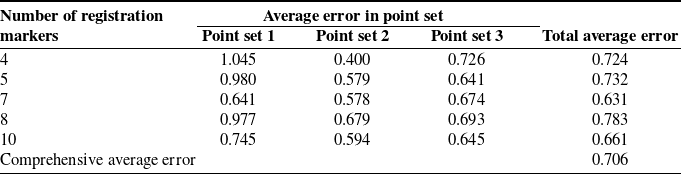
were calculated, and the average value of all point pairs’ deviations was determined, serving as the error in computer image-guided surgery test. The experiment was conducted by 5 groups using 4, 5, 7, 8, and 10 registration markers, respectively. According to the aforementioned procedures, each group was conducted by three different measurement sets comprising 10 points. The total average error of each group is shown in Table II. The results show that the maximum error for computer image-guided surgery based on point registration is less than 0.8 mm. The error distribution does not show any obvious regularity and exhibits significant fluctuation, the reasons of which include spatial registration error, 3D reconstruction error, manual operation error, etc. The human-interactive operation error is the main part to a certain extent.
The results of computer image-guided surgery test unit: mm.

5.2. Analysis of the impact of the number of registration points on accuracy
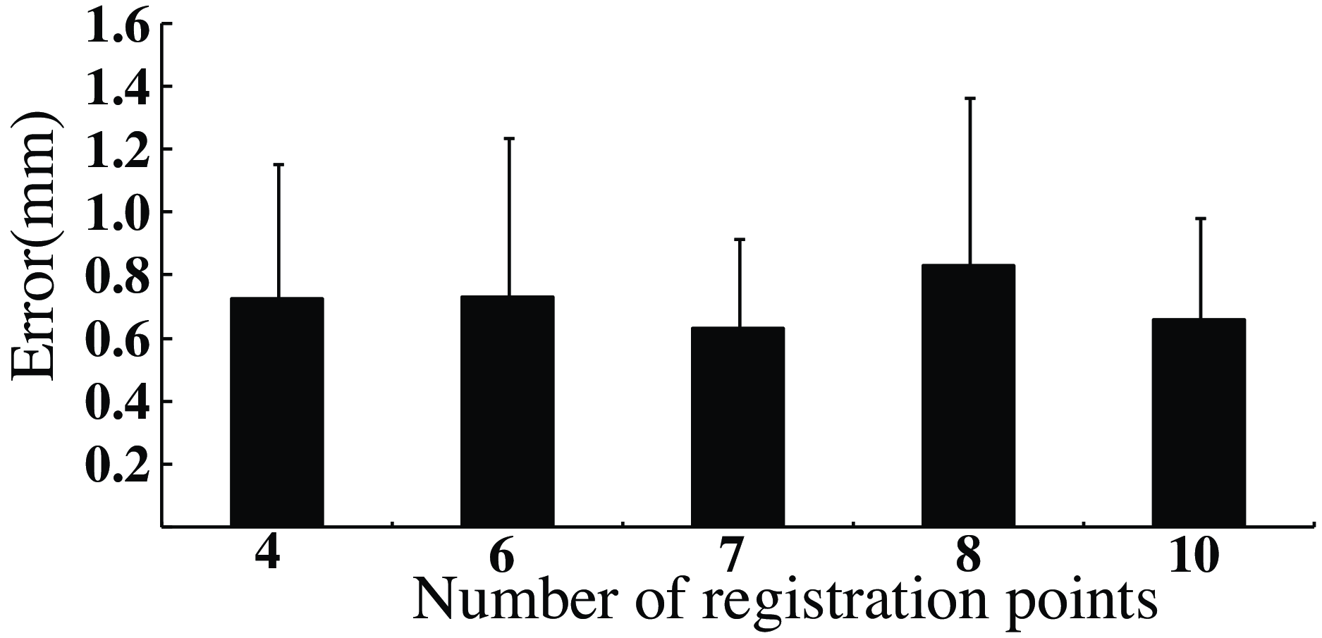
Based on the results from section 5.1, in the spatial registration method with external markers, the number of registration markers can have varying impacts on the precision of computer image-guided surgery [Reference Zhao, Liao, Wu, Zhang, Shi and Yan26]. As shown in Figure 11, by analyzing the test errors, there is no obvious positive correlation between the increase of registration markers’ number and the improvement of accuracy. There is no significant difference in the average errors with different numbers of registration markers. However, the error value tends to be more stable with 7 registration points, which can relatively improve the navigation accuracy and stability.
Analysis of the point number on precision.

5.3. Animal experimental evaluation of the robot-assisted surgery
5.3.1. Robot-assisted mandibular reconstruction surgery
Goat skulls aged eight months to one year were used as experimental subjects. Part of the goat’s mandibular bone was surgically removed to simulate a mandibular defect, and a resin model was designed as the fibula graft implant. Under sedation anesthesia, titanium screw markers were placed on the cranio-maxillofacial area of goats, followed by CT scanning and 3D model reconstruction. A preoperative surgical plan was developed for unilateral mandibular defects and fibula grafts. The fibula segment implant was replaced by the resin model with markers. Intraoperatively, the positioning brackets were installed, the robotic systems were initialized, and the spatial registration was achieved based on the methods in section 4. Under the computer image guidance, the mandible was restored to the position consistent with the 3D model, and the unilateral mandibular body was resected according to the designed osteotomy line to form a mandibular defect, as shown in Figure 12.
Image-guided osteotomy line localization and defect formation.

Due to the small size of the goat’s skull, the surgical operating space was relatively narrow, resulting in collisions to use three manipulators simultaneously to operate the bone segments. Therefore, two manipulators were used at the same time to fix the resin implant with ascending ramus bones in two stages. Initially, the right proximal bone segment was connected to the right manipulator, and the middle manipulator held the resin implant. Using the methods described in section 4.3, the spatial registration of the bone segment and the implant was performed by probe, as shown in Figure 13(a). According to the preoperative surgical design, the manipulators were controlled to adjust the bone segment and implant to the ideal position and orientation. The surgeons fixed the implant and the right proximal bone segment, as depicted in Figure 13(c). Subsequently, the middle manipulator was moved away. The left proximal bone segment was connected to the left manipulator, which was then controlled to adjust the bone segment to the ideal position and orientation after bone spatial registration. The implant and the left proximal bone segment were fixed by surgeons, as shown in Figure 13(d). Finally, the manipulators were released, and the incisions closed. In the experiment, the surgeons used probe to verify the positions of bone with titanium markers, and controlled the fine motion of the manipulators with force interaction devices as needed, as shown in Figure 13(b).
Robot-assisted mandibular reconstruction surgery.

Postoperatively, the CT scans were performed again to reconstruct the 3D model, which was compared and analyzed with preoperative 3D model, as shown in Figure 14. The average difference of the fibula segment was 2.175 mm compared with the preoperative design. The average error of the mandibular ramus bone segment was 1.17 mm, and the average error of the contralateral mandibular bone segment was 2.475 mm. The robotic movements were smooth throughout the experiment, and the morphology of the mandible after reconstruction was basically consistent with the preoperative design.
Error analysis of robot-assisted surgery.

5.3.2. Control group: computer-guided mandibular reconstruction surgery
Goat skulls aged eight months to one year were also used as experimental subjects. Preoperative procedure was the same as that in section 5.3.1. A resin implant was also designed as the fibula graft implant. Intraoperatively, the unilateral mandibular defect segment was resected according to the preoperative surgical design after spatial registration. The resin implant was placed and positioned by manual grasping with the computer image-guided navigation. Finally, the bone segments were fixed without robot assistance, as shown in Figure 15. Postoperatively, the CT data was reacquired to reconstruct the postoperative 3D model, which was compared with the preoperative 3D model for error analysis. The average error was 2.935 mm.
Computer-guided surgery and error analysis.

5.3.3. Control group: freehand mandibular reconstruction surgery
This experiment adopted the traditional measurement methods and surgeon experience for surgical procedures. After CT scan and 3D model reconstruction, the preoperative surgery plans were designed, and the resin implant model was made. During the operation, a ruler was used to determine the mandibular osteotomy region. The resin implant was placed in the defect area to ensure continuity of the mandibular margin, and titanium plates were used to fix the bone segments, as shown in Figure 16. Postoperatively, the error spectrum analysis between preoperative model and postoperative model was conducted. The average error was 3.435 mm.
Freehand surgery and error analysis.

6. Summary and discussion
Based on the operation analysis of mandibular reconstruction surgery, this paper integrated the robotic technology and computer image navigation techniques for the mandibular reconstruction surgery. A robot-assisted navigation system for mandibular reconstruction surgery was designed to aid surgeons in the precise positioning and stable manipulation of free bone segments. The robot consisted of three manipulators, each of which consisted of six active DOFs and one passive DOF. The kinematic models of the manipulators were established, and the forward and inverse kinematic analyses were conducted. Subsequently, an improved ICP algorithm of spatial registration was proposed, realizing the transformation of the spatial coordinate systems and the spatial localization of free bone segments. In conjunction with robot kinematics, a hand-eye calibration method for multi-arm robots based on infrared optical localization was introduced, achieving "hand-eye" calibration for the three robotic manipulators. In traditional method, the positioning bracket is directly installed on the end-effector. An increase in the number of manipulators may lead to mutual occlusion, resulting in positioning failure. The method in the paper installs the positioning bracket on the robot body to achieve hand-eye calibration. The three manipulators will not occlude the positioning bracket installed on the robot body, avoiding the problem of positioning errors due to mutual occlusion between manipulators. Moreover, even if the number of manipulators continues to increase, the number of positioning brackets will not increase, effectively reducing redundancy and complexity of the robotic system. Finally, the experiments were conducted to assess the accuracy of the computer image-guided surgery and animal verifications. The results showed the feasibility and effectiveness of the robot-assisted navigation system for mandibular reconstruction surgery, which can improve the positioning accuracy of bone segments to ensure the precise intraoperative implementation of the preoperative surgical design.
There are still several key technical challenges that require further investigation. The structural and joint configuration of the robot need to be further optimized, especially the passive joint needs to be further optimized to improve the dexterity and operability of the manipulators. During the experiment, there was a situation in which the robot could not update the path in time to precisely track the targets after head’s position variation. In the future, the online planning and real-time path updating technology of robot should be deeply studied to adapt to the frequent target changing in clinical applications.
Author contributions
Xingtao Wang, Zhen Qiu, and Yubin Xue proposed the overall structure of the research. Xingtao Wang drafted the manuscript. Xingchen Liu proofread the manuscript. Xingtao Wang and Xingguang Duan designed and implemented the robotic system. Changsheng Li provided suggestions and guidance on the revised version. Jiang Deng, Xiaojing Liu, Jing Wang performed the experiments and analyzed the data with the support from Chuanbin Guo and Yubin Xue. All authors discussed the results and were involved in critical revisions of the manuscript.
Financial support
This study was supported by the China National High-Tech R&D Program (863 program) under grant no. 2012AA041606.
Competing interest
The authors declare no conflicts of interest.
Ethical approval
No case report was submitted in this paper, and no human subjects were involved in this research. The use of a deidentified CT scan originally used to generate the skull and mandible models was not human subjects research, and all study participants are aware of this. This study adheres to academic ethical standards and is committed to maintaining transparency and credibility in research.