1. INTRODUCTION
A laser ion source (LIS) can provide high-brightness heavy-ion beams and intensive efforts had been devoted in the previous decade to establish high-current powerful heavy-ion sources (Haseroth & Hora, Reference Haseroth and Hora1996). This feature suits for the application of heavy-ion inertial fusion (HIF) (Hora, Reference Hora2004). The achievable beam current was estimated to fulfill the HIF scenarios as explained in our previous work (Okamura et al., Reference Okamura, Sekine, Takahashi, Kondo and Kanesue2014). The major remaining issues are stability and quality control of the high-current beam from a LIS.
At Brookhaven National Laboratory (BNL), we developed a LIS (Kondo et al., Reference Kondo, Yamamoto, Sekine and Okamura2012; Kanesue et al., Reference Kanesue, Okamura, Alessi, Beebe, Pikin, Raparia, Liaw, Lambiase, LoDestro, Costanzo, Lehn, DeSanto, Olsen, Steszyn, Sekine, Ikeda and Kondo2014) to provide singly charged various ions to the electron beam ion source (EBIS) (Alessi et al., Reference Alessi, Barton, Beebe, Bellavia, Gould, Kponou, Lambiase, Lockey, McNerney, Mapes, Mameris, Okamura, Phillips, Pikin, Raparia, Ritter, Snydstrup, Theisen and Wilinski2010). The first beam commissioning was done in March 2014 and since then solid-based ion beams have been provided by the LIS to NASA space radiation laboratory and relativistic heavy-ion collider. We could continuously deliver the beams to the users everyday with excellent beam stabilities. This was an encouraging result to verify a possible stability and reliability of the LIS for a HIF power plant.
Simultaneously we started to examine the quality control of the extracted beam from a LIS. One of the subjects to be solved is the beam current profile. The design of a HIF accelerator always combats against the space-charge effect. To mitigate this difficulty, the beam current profile in the time scale must have a rectangular wave function. In spite of this demand, a typical beam profile supplied by a LIS follows a shifted Maxwell–Boltzmann distribution function (Esposito et al., Reference Esposito, Lippert, Schneider, Wokaun, Donnelly, Lunney, Tellez, Vadillo and Laserna2010), since the plasma is heated by the classical laser energy absorption process. To manipulate the beam current profile, we proposed to employ a pulsed solenoid at the plasma drift section of a LIS. However, this modification also affects on the beam emittance. To investigate the effect of the short-pulsed solenoid, we measured the beam current shape and emittance.
2. EXPERIMENTAL SETUP
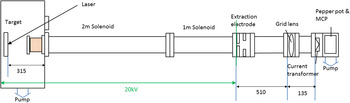
A newly wound simple coil was added to our existing LIS (Takahashi et al., Reference Takahashi, Okamura, Sekine, Cushing and Jandovitz2013) which was originally developed as a test ion source for the EBIS injection. The experimental layout is shown in Figure 1.
Experimental layout.

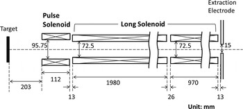
As a laser target, we used an iron plate which had 99.5% of purity. A Nd:YAG laser (Quantel laser Brilliant B TWINS, 850 mJ, 1064 nm, 6 ns) emits laser light on to the target surface and the laser power density was controlled to be about 5 × 10⁸ W/cm2 using a plano-convex lens to mainly induce Fe1+ ions. According to our experiences, more than 95% of particles consisted of single charge state ions. The laser incident angle was 30° and the supplied laser energy on to the target was 630 mJ. The laser spot shape was ellipse (3 mm × 4 mm). The pulsed solenoid had 50 turns coil wound around 95 mm diameter glass tube and was placed 203 mm from the target. The coil was connected to a capacitor and a fast solid-state switch. A high-voltage power supply, which supplied up to 3 kV, charged the capacitor (0.63 μF). The time constant of the rising magnetic field achieved 5 μs. The maximum field was about 500 G. Behind the pulsed coil, a long static solenoid comprised by two separate windings was connected. After the static solenoid, we had a voltage gap with 15 mm of diameter extraction hole. The detailed dimensions of the coils are shown in Figure 2.
Positions of solenoids. The 3 m static solenoid comprised of 2 and 1 m solenoids with a 26 mm gap. We have experimentally confirmed that the effect of the magnet gap was negligible on the beam current.

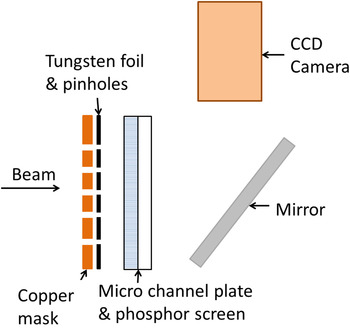
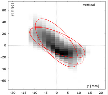
To measure the emittances, a pepper pot monitor was installed as shown in Figure 1. The platform, where the plasma expanded, was biased at 20 kV and the extracted ions were detected by the pepper pot monitor. To focus the ion beam on the 43 mm diameter sensing area of the monitor, a gridded lens was used. According to a finite-element method simulation, −9.0 kV of the typical applied voltage on the lens gave 330 mm of the focal length. The structure of the monitor is indicated in Figure 3. A copper mask plate was attached just before the tungsten foil which has 100 μm holes. The pinholes were spaced 2 mm horizontally and vertically. The copper plate was biased to suppress the secondary electrons and could provide beam current information. The particles filtered by the foil were converted to electrons at the micro channel plate and emit a pattern on the phosphor screen. The image of the pattern was taken by the camera and was processed to express the emittance in the phase space. A typical processed image is shown in Figure 4. The minimum exposure time of the camera was 20 μs, so that we could obtain an emittance at a certain time slice within 20 μs.
Structure of pepper pot emittance monitor.

Typical emittane based on captured image by camera.

3. EXPERIMENTAL RESULTS
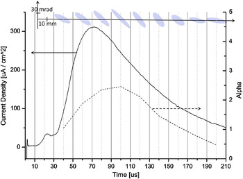
Figure 5 shows a current profile without any solenoidal fields captured by the copper musk. The current form was divided into several time slices and each covers 20 μs of the period. Then the root-mean-square (RMS) emittance ellipses are plotted at the top of the figure. Each ellipse represents the measured Twiss parameters of the sliced segment. For instance, the first ellipse shows the Twiss parameters of the beam current which reached the monitor from t = 30 to 50 μs. The dotted line shows the variation of α of the Twiss parameters. We could clearly observe that the emittance rotated within a single ion beam pulse of the laser ion source.
Beam current and rotating emittance ellipse.

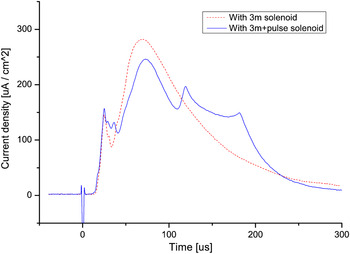
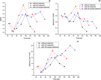
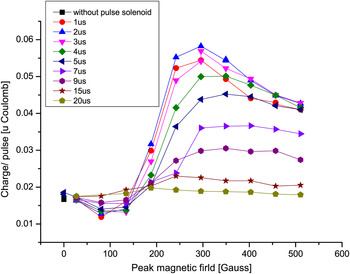
Figure 6 shows the pulsed solenoid effect on the current. The red-dotted line shows the current using only the 3.0 m static solenoid and the blue line expresses the current using both the static and the pulsed solenoid. The static solenoid induced 4.2 G of magnetic flux density. The pulsed coil was triggered at 5 μs after the laser exposure and the field reached 144 G at 15 μs. We could magnify the current within the specific period and make another peak in an ion beam pulse induced by the LIS. In both the cases, the measured overall emittance was 0.047π mm mrad (normalized RMS). The changes of the Twiss parameters are plotted in Figures 7a, 7b and 7c. In the low-current region, in the tail of each current form, the image size at the pepper pot was too small, <10 mm, to estimate the emittance profiles. These in-accurate points were omitted in the graphs. When the only static field was applied, it simply enhances the entire range of the graphs. However, the pulsed solenoid could change the moving patterns of the Twiss parameters. The α value, which shows the angles of ellipse, could have less variation throughout the whole pulse when the pulsed solenoid was ignited. We also confirmed that the timing and the amplitude of the second peak can be changed by adjusting the trigger timing and the field strength of the pulsed solenoid field. The obtained total ion charges were plotted in Figure 8.
Current profiles with and without pulsed solenoid.

(a) Changing α. (b) Changing β. (c) Changing γ.

Pulsed solenoid effect on total charge.

4. DISCUSSIONS
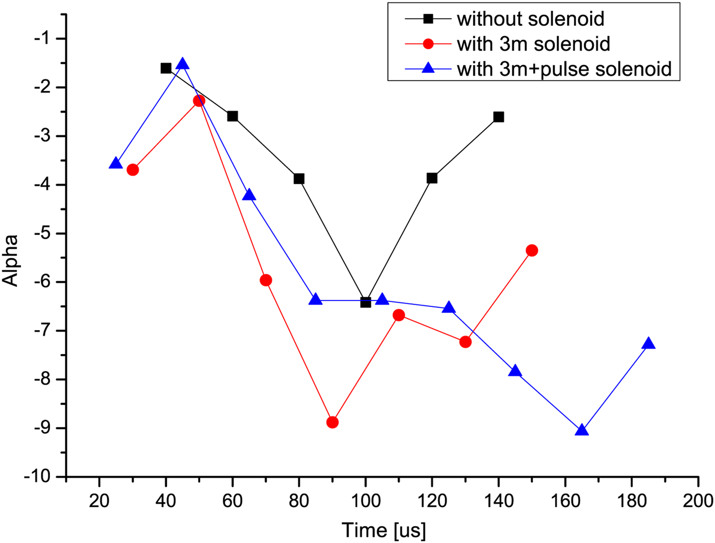
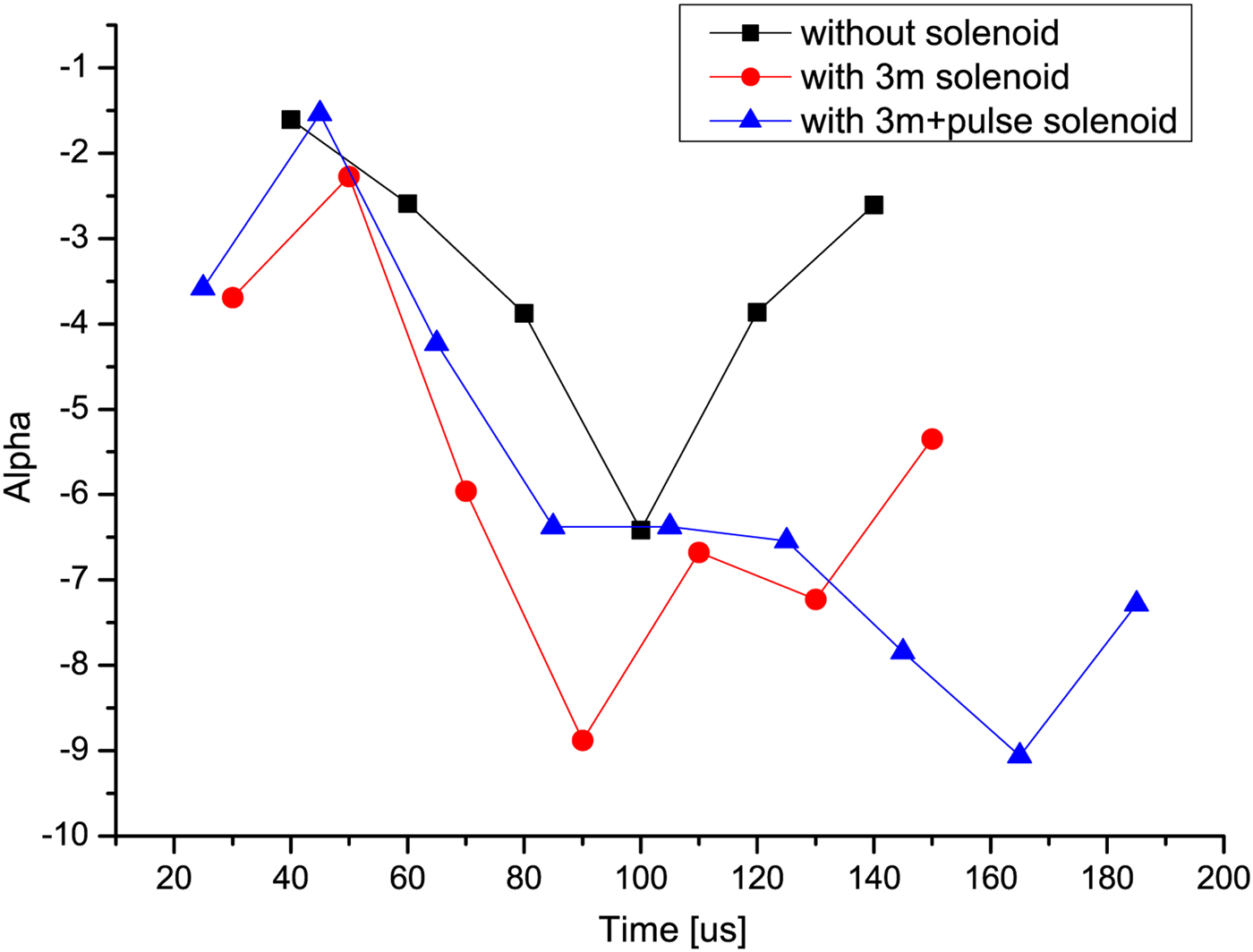
To investigate the beam extraction condition, the emittance information at the extraction point is demanded. Then we tracked the envelopes of the beam backwards from the monitor to the beginning of the grounded potential point. The space-charge force was neglected. The simulated diameters of the envelope at the gridded lens and at the beginning point are about 48 and 37 mm, respectively, and those seem appropriate values. Now we can assume that the recalculated Twiss parameters represent the beam shape just after the extraction. Figure 9 shows the α of the Twiss parameter as a function of time which was closely related to the shape of the beam extraction sheath (Benilov, Reference Benilov2009). After 100 μs, we can see the clear differences and observe the effect of the pulsed solenoid field. We confirmed that the both beam current shape and emittance variation in a pulse can be manipulated by a pulsed solenoid.
Orientation of emittance ellipse at the extraction point.
7. CONCLUSION
We tested the pulsed solenoid to control the beam current shape and the emittance of the LIS. We found that the solenoid field could change those parameters. To obtain a flat beam current with a constant emittance, we may need to control the pulsed field using multiple power supplies or multiple coils. Also the extraction gap voltage may need to be varied. Although further studies are indispensable, the pulsed solenoid is useful to control the beam current shape and beneficial to realize a LIS for HIF.
ACKNOWLEGMENTS
This research was supported by NASA, DOE of the USA, JRA system from RIKEN of the Japan, and their supports are gratefully acknowledged.