
I. INTRODUCTION
In the last decades, many articles about mechanical properties and fatigue behavior of nanocrystalline and ufg materials have been published. Reference Erb1–Reference Hahn and Meyers6 Most researchers argue that special grain size distributions and textures improve the mechanical behavior of the material, but they neglect the synthesis method and boundary conditions under which the material was produced. Reference Meyers, Mishra and Benson3,Reference Hahn and Meyers6 The microstructure of materials is thereby not sufficiently described by the grain size distribution and texture analysis. Even more crucial for the mechanical properties or the fatigue performance of the material are other strong influencing factors like dislocation densities or amount and type of impurity atoms and especially where they are located in the material. The keyword to this topic is segregation at grain boundaries, which has been known for many years to have a strong impact on the strength of the boundaries and, therefore, on the macroscopic material properties. Reference Johnson, Doherty, Kear and Giamei7,Reference Briant8
There are articles, of course, which describe the influence of the production process on the microstructure, respectively, grain size and texture Reference Cziráki, Gerőcs, Tóth-Kádár and Bakonyi9 and sometimes also on mechanical properties as in the case of high pressure torsion experiments, Reference Leitner, Hohenwarter and Pippan10 but often, the correlation between grain size, dislocation densities, production technique, and contained impurity atoms is not mentioned. This is especially problematic for production techniques which are very sensitive to a slight modification of any process parameter or which are strongly dependent on the use of additives during the processing Reference Oniciu and Mureşan11 to obtain nc grain sizes like the electrodeposition process. Unfortunately, this leads to an incorporation of impurities in the sample material, although the amount of the incorporated impurities is often well below 0.04 wt%. Reference Osaka12 The problem is that without such impurities, it is nearly impossible to reduce the grain size down to the nc regime and prevent grain growth, even at room temperature. Electrodeposition is thereby one of the most common techniques for the production of nanocrystalline and ultrafine-grained materials and is a very powerful tool to modify their properties as well, simply by modifying parameters like bath composition, plating geometry, temperature, pH-value, bath agitation, filtration, substrate material, pulse parameters (current density, on-time, and off-time), and, of course, the used additives. A modification of these parameters leads to a variety of grain sizes, textures, residual stresses, dislocation densities, twins, impurity atoms incorporated into the material, porosity, and many other features.
The reason why nanocrystalline materials are so interesting is mainly because of their high strength, hardness, and good tribological properties, which are improved by a grain refinement down to several ten nanometers. Unfortunately, there are two major problems with nanocrystalline materials apart from the huge effort of producing them:
-
(i) The thermal and mechanical stability is difficult to handle and often relatively low, which means that the grains start to grow at slightly elevated homologous temperatures, and the material loses its good properties. Reference Klement, Erb, El-Sherik and Aust13
-
(ii) The ductility of nanocrystalline metals is usually much lower than that of their coarse-grained counterparts.
Commonly, heat treatments can be used to increase the ductility again by grain growth, but as a logical consequence, the strength of the material is reduced again in this process. Electrodeposited nanomaterials often show a special behavior concerning the grain growth mechanism. Because of the grain refiners that are used, the grain growth of special grain boundaries is preferred, causing them to grow faster than others. This is called abnormal grain growth and leads to the formation of bimodal microstructures, if the temperature that is reduced before the grain size distribution becomes monomodal again. Such bimodal nc/ufg microstructures are often a good compromise between strength and ductility. The reason for this is that the larger grains can deform much easier and improve the ductility of the material, which can—in the case of fatigue—slow down the crack propagation rate of a crack, while the nanograins provide the high strength of the material. Reference Tellkamp, Lavernia and Melmed14,Reference Hosseini-Toudeshky and Jamalian15 Höppel et al. Reference Höppel, Korn, Lapovok and Mughrabi16 reported a good effect on the fatigue performance of bimodal microstructures if the loading conditions are strain-controlled, whereas under stress control, this is not the case. Liu et al. Reference Liu, Mi and Tian17 reported an improvement of fracture toughness by using bimodal nanocrystalline materials instead of nc materials and that the critical stress intensity factor is larger if the grain size of the large grains in the bimodal microstructure is increased. Kikuchi et al. Reference Kikuchi, Hayami, Ishiguri, Guennec, Ueno, Ota and Ameyama18 showed that for a bimodal aluminum alloy (ufg to coarse grained), the tensile strength can be increased with increasing a fraction of ufg grains, while the total elongation remains nearly constant up to a volume fraction of ufg grains of about 54%. If the volume fraction is increased further, the elongation obviously drops.
However, most investigations of bimodal microstructures in respect of fatigue are in a grain size regime between ufg and coarse-grained materials, and there are much fewer studies concerning a bimodal distribution in the nc to ufg regime. The question remains on how these microstructures behave similarly to their coarse-grained counterparts and how their behavior is influenced by the production method.
In the following, the production, characterization, and mechanical testing is described in the case of nanocrystalline to ultrafine-grained nickel produced by pulsed electrodeposition (PED).
II. THEORETICAL BACHGROUND
A. Thermal stability of nanocrystalline materials
As mentioned above, the low thermal stability of most nanocrystalline materials is one of the main problems for many applications. The reason for this is found in the huge amount of grain boundaries. As grain growth is generally driven by the reduction of the surface/grain boundary energy, the driving force for grain growth is especially high for nc materials, which leads to grain coarsening at slightly elevated temperatures. For instance, Ames et al. Reference Ames, Markmann, Karos, Michels and Tschöpe19 describe that grain growth in nc palladium produced by inert gas condensation already occurs at room temperature, although Pd has a melting point of 1555 °C. Therefore, grain growth is typically expected at much higher temperatures. Starting from grain sizes of about 10 nm, surprisingly the grain growth did not stop until some grains reach a size of about 10 µm. This indicates that there is no significant amount of backpressure to the driving force for the grain growth. To increase thermal stability, either the movement of grain boundaries or their velocity v has to be decreased. The velocity is thereby given by:
 $$v = M \cdot p\quad ,$$
where M is the mobility of the grain boundary and p the driving force. Following this equation, a reduction of M or p leads to an increase of the thermal stability of the material. The most important mechanisms to reach this aim are shortly summarized hereafter:
1. Reduction of the driving force of grain boundary motion
To increase the stability of grain boundaries, one possibility is to decrease the driving force p, which is proportional to the grain boundary energy γGB and inversely proportional to αGB, which is a constant concerning the curvature and the grain diameter D which cannot be changed without changing the grain size.
 $$p = {{2{\gamma _{{\rm{GB}}}}} \over {{\alpha _{{\rm{GB}}}}D}}\quad .$$
The grain boundary energy is thereby a complex function of multiple influencing factors such as type of the grain boundary, misorientation, segregation, etc. Reference Molodov and Shvindlerman20 with the result that a quantification is nearly impossible. However, Kirchheim et al. Reference Kirchheim21–Reference Liu and Kirchheim24 and Wimmer et al. Reference Wimmer, Smolka, Heinz, Detzel, Robl, Motz, Eyert, Wimmer, Jahnel, Treichler and Dehm25 reported the reduction of grain boundary energy respectively a decrease of the driving force for grain growth by segregation of mostly small amounts of phosphor impurities. Krill, Ehrhardt, and Birringer Reference Krill, Ehrhardt and Birringer26 also investigated this topic and developed an equation to describe the grain boundary energy dependent on segregation. They found that theoretically, the grain boundary energy can be reduced to zero, which would lead to a thermodynamically “stable” nc microstructure.
2. Zener pinning
One well-known mechanism to reduce grain boundary motion is the so-called Zener pinning described by Zener in the 1940s. Reference Rollett, Humphreys, Rohrer and Hatherly27 The equation of Zener is based on the pinning effect of some spherical particles of the second phase at a grain boundary and is given by
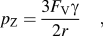 $${p_{\rm{Z}}} = {{3{F_{\rm{V}}}\gamma } \over {2r}}\quad ,$$
where p Z is the Zener force, F V the volume fraction of particles, r the particle radius, and γ the surface energy between particles and matrix. As long as p Z is larger than the driving force p, the grain boundary is pinned and grain growth is inhibited.
Koch et al. Reference Koch, Scattergood, Saber and Kotan28 described the theoretically possible increase in thermal stabilization using the Zener model compared to a thermodynamic stabilization. They reported on an increase of the thermal stabilization of Zr doped Fe to homologous temperatures of 0.65 or 900 °C by a combination of both mechanisms. Morris et al. Reference Morris and Morris29 investigated a Cu–Zr alloy produced by mechanical alloying and containing zirconium carbide nanoparticles. The initial grain size was about 60 nm and even after heat treatment at 900 °C for 1 h, the grains only grew slightly to an average grain size of about 70 nm. There are other studies of Bachmaier et al. who reported on a significant increase in the thermal stability of CNT reinforced materials and particle pinning in Ni with oxide particles. Reference Bachmaier, Hohenwarter and Pippan30,Reference Bachmaier and Pippan31
3. Solute drag effect
One of the most important stabilization mechanism, especially in the case of electrodeposition of nc metals, is the solute drag effect described by Cahn, Reference Cahn32 Lücke and Stüwe Reference Lücke and Stüwe33 in the 1960s. The authors discuss the pinning effect of impurity atoms on the grain boundary mobility dependent on different influencing factors, e.g., the diffusion velocity of impurity atoms compared to the velocity of the grain boundary. Only small amounts of impurity atoms suffice to reduce the mobility of grain boundaries and thereby improve the thermal stability of the material drastically, especially at low temperatures or driving forces. Reference Rollett, Humphreys, Rohrer and Hatherly27
Because of the inhomogeneous segregation of impurity atoms at different types of grain boundaries, the growth mechanism is influenced in such a way that some grains grow preferentially, consuming others, while the matrix remains nanocrystalline. This behavior is known under the term of abnormal grain growth leading to bimodal microstructures, which will be discussed further in this article.
The solute drag effect is very important for the electrodeposition, where “grain refiners” are used to obtain nc grain sizes. These refiners are additives—mostly organic ones—which are dissolved in the electrolyte and adsorbed at the cathode, where they are (partially) incorporated into the deposited metal. Most grain refiners contain sulfur or phosphor, which are known to exhibit strong grain boundary segregation in, e.g., nickel. This is the reason for the strong pinning effect on the grain boundaries, even if only small amounts are added to the electrolyte. A common grain refiner which is used during the deposition of nickel is for example saccharine. Osaka et al. Reference Osaka12 investigated the mechanism of adsorption in the case of saccharin and thiourea during the electrodeposition of nickel and came to the conclusion that only/mainly the sulfur atoms are incorporated into the deposited nickel while most of the contained carbon remains in the electrolyte. When the molecule adsorbs at the cathode, the bonding between parts of the molecule can be broken and only the sulfur-containing part is incorporated into the deposit. Apart from the pinning effect, grain refining additives are important for the electrodeposition because the metal ions in front of the surface area cannot grow at the previously existing crystallites and have to create a new nucleus with a different orientation, resulting in the formation of new grains and in the formation of an alternative growing texture.
Thus, the addition of grain refiners acts in two different ways:
-
(i) The nucleation rate is increased and
-
(ii) grain growth is hindered by blocking the diffusion of ad atoms along the cathode surface. Reference Choo, Toguri, El-Sherik and Erb34,Reference Natter and Schmelzer35
The influence of such additives during an electrochemical plating process is discussed in many studies Reference Natter and Hempelmann36–Reference Oniciu and Mureşan39 in respect of surface morphology and also the grain size stabilization up to at least slightly elevated temperatures. As far as the authors know, there has not been any production of macroscopic nc metals by electrodeposition without using any additives during the plating process.
B. Bimodal microstructures in respect of fatigue
Hibbard et al. reported on abnormal grain growth of electrodeposited metals caused by thermal activation. Reference Hibbard, Aust, Palumbo and Erb40 In this case, the growing process starts by an abnormal grain growth mechanism, leading only to bimodal microstructures if the temperature is reduced again at a special point. Otherwise, the microstructure evolves to a monomodal distribution again after a certain time. Reference Qian, Karaman and Marx41 The interesting question is whether such bimodal microstructures improve or impair the mechanical properties under static and dynamic loading. Höppel and Mughrabi et al. Reference Höppel, Korn, Lapovok and Mughrabi16,Reference Aronson and Ritchie42 found that in some cases and under special loading conditions, bimodal microstructures can form by dynamic recrystallization. For thermally induced bimodal microstructures due to annealing, they tested the fatigue performance under stress-controlled (Wöhler/S–N plot) and strain-controlled (Coffin–Manson plot) conditions. The authors conclude that an enhancement of mechanical properties by an optimized annealing process is possible in general and after that, the material can sometimes exhibit enhanced monotonic and fatigue properties. Compared to a coarse-grained reference material, the bimodal samples showed enhanced fatigue properties in the S–N plot and in the Coffin–Manson plot, but compared to an ufg (not bimodal) microstructure, the fatigue performance was enhanced only under strain-controlled conditions. However, the bimodal microstructure the authors investigated was in a ufg to a coarse-grained regime, and the remaining question is how these results can be transferred to even smaller grain sizes and bimodality such as an nc to a ufg microstructure, which is discussed in this article.
III. EXPERIMENTAL DETAILS
A. Sample production and preparation
The samples were produced by pulsed PED with a vertical plating geometry. The electrolyte was sulfamte-based containing some further additives like boric acid as a pH buffer, nickel chloride to provide a better dissolution of the anode material, the surfactant sodium dodecyl sulfate as a wetting agent, and the grain refiner sodium saccharin. The concentration of the sodium saccharine was 0.4 g/L. To keep the electrolyte clean from suspended matter, a filtration was used and additionally, a flat stirrer in front of the copper cathode provided a nearly laminar flow.
The pulse parameters during the plating process are: I pulse = 45 mA/cm2, t on = 5 ms; t off = 10 ms.
The plates have a dimension of 35 × 70 × 1.5 mm. After the plating process, the copper cathode is removed and samples are cut by electro-discharge machining (EDM). The sample design for crack propagation experiments is referred to ASTM E647-13 for the CT specimen with: W = 12 mm, B = 1 mm, and a chevron notch produced by EDM too. The crack length was measured using the electric potential drop technique. For stress–strain curves, a flat tensile specimen geometry is chosen. Because of the small sample dimensions, it is difficult to ensure a reliable mounting of the current lead positions and potential lead positions. Therefore, the sample design was slightly modified to mount the respective wires by soldering it at the protruded sampling points. The current input and potential lead position was thereby chosen in regard to the work of Aronson and Ritchie Reference Aronson and Ritchie42 but taking into account the limitation of the small sample size and applicability with the equally small sample holder.
After the samples were cut as previously described, some of them were heat treated to adjust different microstructures. SEM micrographs and micro hardness measurements indicate the evolution of the microstructure after different heat treatments. The SEM micrographs were evaluated by common image analysis tools. Additionally, some electron backscatter diffraction (EBSD) scans were performed and compared to the results from the image analysis. Because abnormal grain growth first starts at about 190 °C but is quite slow at this temperature, the heat treatments of the nc samples are performed as follows:
-
(i) 210 °C, 150 min for the bimodal microstructure nc/ufg.
-
(ii) 210 °C, 48 h for ufg samples.
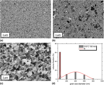
To ensure reliable and repeatable testing conditions and, of course, for the further characterization, all samples were grinded and polished to exactly the same thickness of 1 mm using SiC paper starting with P600 to P4000 for the grinding and continuing polishing using an ATM polycrystalline diamond suspension with a particle size of 3 and 1 µm. To analyze the microstructure in SEM, a final polishing with an oxide polishing suspension was additionally applied. SEM pictures of the so-prepared three different microstructures are shown in Fig. 1.
SEM micrographs of (a) nc nickel, (b) bimodal microstructure after a heat treatment of 210 °C for 150 min [with corresponding grain size distribution (d)], and (c) the ufg microstructure after 210 °C for 48 h.

B. Testing system and conditions
All static and dynamic tests were performed by the servohydraulic testing system INSTRON 8511.20 (Instron, Norwood, Massachusetts), which was upgraded with a DOLI controlling system. For the measurement of the stress–strain curves, a strain gauge from MTS was used on flat tensile specimen. As mentioned above, the crack propagation experiments were performed with CT specimens at an R value of 0.1 and a testing procedure according to ASTM E647-13. The crack propagation was measured with the electrical potential drop technique. Because of the moderate thermal stability of the nc material, the current input had to be set not too high to avoid any heating of the sample. For this geometry, a current of 20 A was a good tradeoff between the crack length measurement resolution and a slight sample heating of about 40 °C. The crack propagation was observed between a/W values of 0.24–0.65 and additionally checked with a long distance video microscope.
IV. RESULTS AND DISCUSSION
A. Microstructure characterization
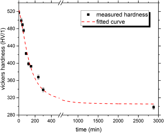
As mentioned above, the first characterization of the material after the production by PED was performed using SEM and micro hardness measurements to correlate the microstructural changes with micro hardness, which is a much faster characterization method. Because of the very small crystallite sizes at the initial state of the samples, a grain size determination was done by X-ray diffraction using a Philips X’Pert PRO MRD (PANalytical B.V., Almelo, the Netherlands). For the evaluation, the method according to Williamson-Hall was used. The so-determined grain size is about 35 nm, which is consistent with the SEM pictures in Fig. 1. For the ufg microstructure, a common grain size determination via the image analysis or EBSD measurements is sufficient, whereas the determination of grain sizes for the bimodal microstructure consisting of both nc and ufg grains is much more challenging. A satisfying approach is the assumption that the small grains of these bimodal microstructures remain nearly at the same size as in the initial stage. If one compares the SEM pictures in Fig. 1, this appears reasonable. The ufg grains can then be measured via image analysis and EBSD scans. The volume fraction of the ufg grains was determined for different heat treatments to adjust a bimodal microstructure composed of about 40% ufg grains to compare the results with prior work. The final annealing time for this ratio was 2.5 h. Representative microstructures of the so prepared samples are shown in Fig. 1. A grain size distribution of the bimodal microstructure is shown in Fig. 1(d).
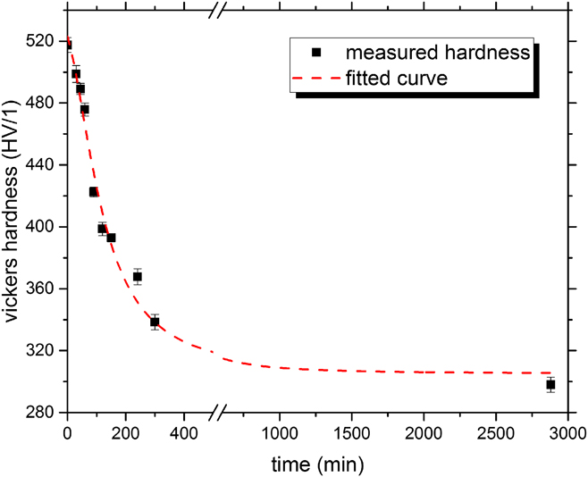
As it is shown in Fig. 2, the micro hardness measurements are in good agreement with the observed changes in the microstructure and can be used as a first and fast parameter for the process control.
Micro hardness measurement versus heating time. Comparing to SEM micrographs shows that the hardness decreases until the microstructure is nearly 100% in the ufg regime.
B. Mechanical properties
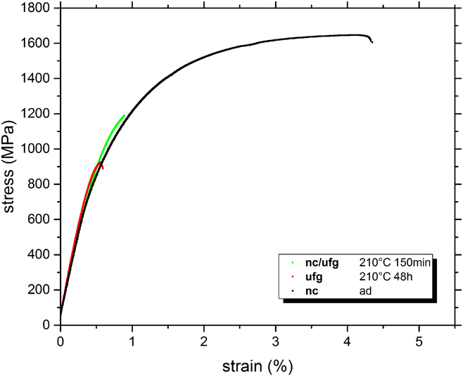
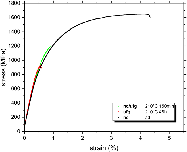
To determine the mechanical properties and estimate suitable stress values for the fatigue experiments, stress–strain curves were measured. It would have been expected that with an increasing volume fraction of the ufg grains, the ductility of the material increases too, but as it is shown in Fig. 3, the opposite is true. Surprisingly, the nc microstructure shows the best fracture strain and also quite a good tensile strength of nearly 1700 MPa and work hardening. To check the influence of the strain rate sensitivity, different tests were performed at various strain rates, but between 10−4 to 1, no significant strain rate sensitivity was observed for the nc material.
Stress strain curves of nc, bimodal and ufg Ni samples. As it is shown, the ductility of the material decreases with increasing heating time. After a heat treatment of several hours, the fracture behavior is quite brittle.
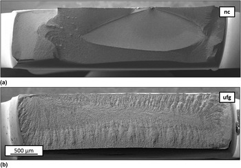
Regarding the fracture surface of the nc and ufg sample, which is shown in Fig. 4, the embrittlement of the material due to the annealing process is confirmed. The most probable reason for that might be the incorporation of sulfur, contained in the grain refiner saccharine. During the annealing process, the mobility of sulfur atoms is increased, enabling them to diffuse to the grain boundaries. Moreover, the volume fraction of grain boundaries is reduced due to the annealing, which leads to a further increase of the local sulfur concentration and thereby to an impairment of the grain boundaries.
Fracture surface of the (a) nc and (b) ufg tensile specimen. The nc sample shows a jagged surface which indicates a more ductile fracture behavior, whereas the fracture surface of the ufg sample is smooth like it is in the case of a brittle fracture.

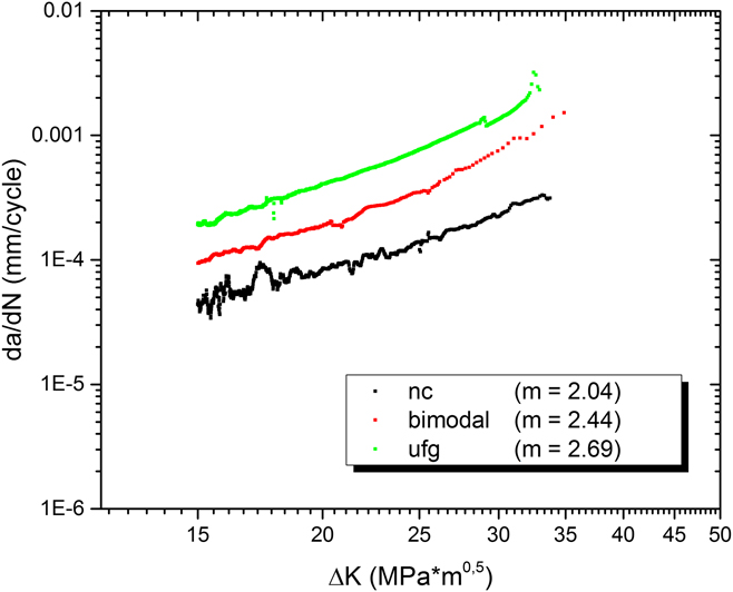
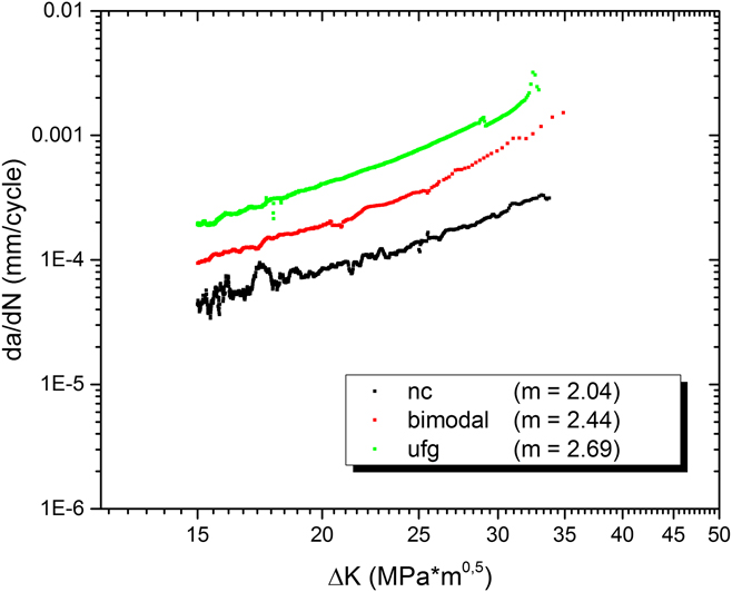
The crack propagation was measured with the help of the electric potential drop technique as mentioned above. To obtain reliable results, a data acquisition rate of 5000 Hz was chosen. The testing frequency was 10 Hz, and due to the limited memory of the system, only every 10th cycle was saved and the number of saved points per cycle was limited to 10. For the evaluation, the measured crack length values were smoothed by a moving average filter over 100 data points. Considering the results from the tensile tests, it is not surprising that the crack propagation curves shown in Fig. 5 confirm the former observations as well. The brittle fracture behavior of the material leads to an increase in the crack propagation rate with increasing annealing time. The slope in the Paris regime is nearly the same for all microstructures (nc: m = 2.04, bimodal: m = 2.43, ufg: m = 2.69), which indicates that there is no significant change in the crack propagation mechanism, although the nc metal shows a much more ductile fracture behavior during tensile measurements. The paris exponent was evaluated between 15 and 25 MPa m0.5. Because of the small sample size and mounting for the electric potential drop technique, it was not possible to use standard load decrease tests to estimate any threshold values. Therefore, the authors tried to measure the threshold values by the K max method. Unfortunately the samples showed a crack propagation by creep because of the higher load values during the test. Therefore, the investigation of threshold values is still outstanding and will be performed in further studies.
Crack propagation curves of the analyzed samples. In agreement with the tensile tests, the annealing leads to a further segregation of grain boundaries and thereby to an embrittlement of the material resulting in a faster crack propagation.
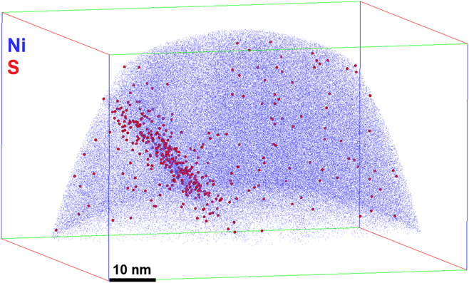
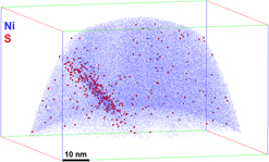
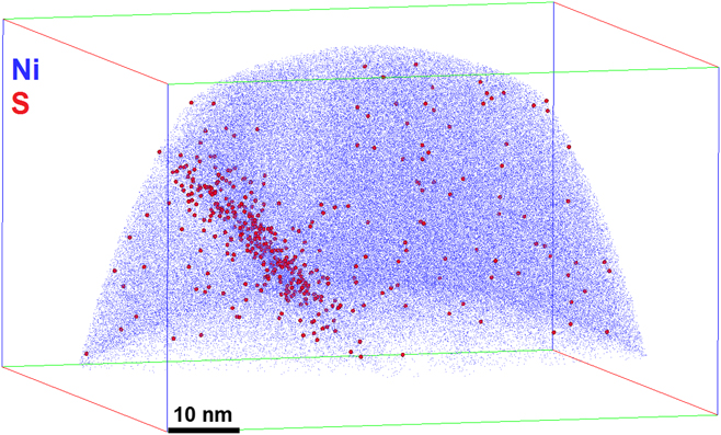
To verify the assumption that this behavior is caused by the incorporated sulfur which segregates at the grain boundaries, atom probe specimens of grain boundaries of the annealed samples were prepared using a focused ion beam system. The result of such a tomography is presented in Fig. 6. It is clearly demonstrated that the sulfur concentration at the grain boundary is strongly increased and thereby the cause of the embrittlement of the material is confirmed. Comparative measurements with samples that were not heat treated showed nearly no local increase of sulfur, which indicates that either the concentration of sulfur at the grain boundaries is below the detection limit of the atom probe or the sulfur is nearly randomly distributed and not only segregated at the boundaries. In both cases, the grain boundary is not weakened enough to show a brittle fracture behavior during tensile or fatigue tests.
Atom probe tomography of a grain boundary of an annealed Ni sample. It is good to see, that the local sulfur concentration at the grain boundary is strongly increased, which verifies the assumption that segregation of sulfur at grain boundaries causes the embrittlement of the material.
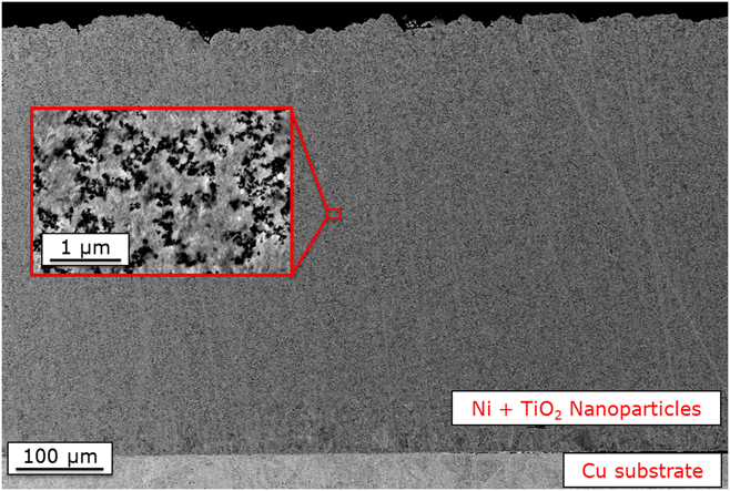
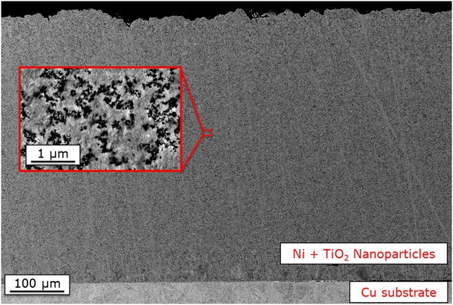
As a logical consequence, it is of course necessary to avoid any embrittlement of the grain boundaries caused by segregation. Because the local segregation increases with decreasing the amount of grain boundaries caused by grain growth, it would improve the material properties if the nc microstructure was stable against any grain growth up to much higher temperatures. One possibility to obtain this is a further stabilization of the material by Zener pinning. Therefore, small nanoparticles have to be incorporated and homogenously distributed into the material. First, experiments by the authors concerning a method for the co-deposition process of metal oxides nanoparticles within the nc nickel matrix have been conducted. With this technique, large amounts of particles can be incorporated into the material which is over several hundred microns in thickness as it is shown in Fig. 7.
Co-deposition of TiO2 in a nc nickel matrix. Except of local agglomerations, a nearly homogenous distribution over the thickness of several hundred microns is reached. Moreover the quantity of incorporated nanoparticles can be modified to very large amounts.
Another option is the synthesis of nc metals without the use of any sulfur or phosphor-containing grain refiners and to use alternative ones. The segregation of these elements is well known to cause an embrittlement of the grain boundaries, but if the segregation of other elements, which have a better influence on the grain boundaries, can be promoted, the mechanical properties can be increased significantly. If this can be reached, a bimodal microstructure might be produced as well and might be able to enhance the mechanical and fatigue properties further.
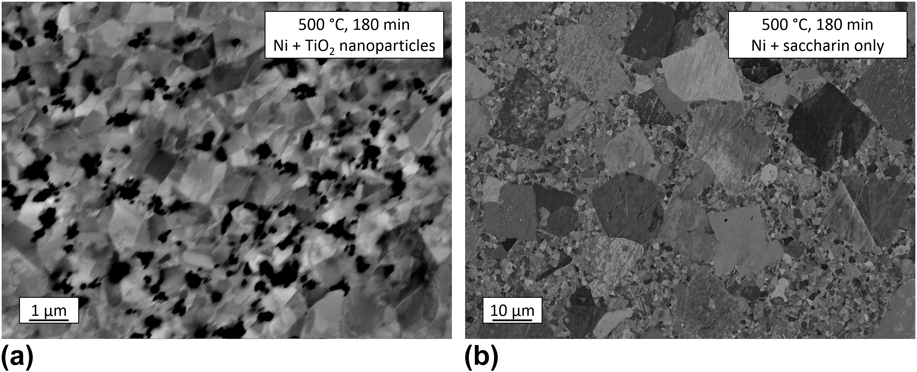
As one can see in Fig. 8, the thermal stability can be increased drastically by adding such particles to the material. The resulting grain size after the heat treatment is in the ufg (<1 µm) regime due to the incorporation of nanoparticles. For the “pure” nickel, the microstructure became bimodal with large grains of sizes more than 10 µm. The remaining challenge is to prevent the local agglomerations of particles in the matrix because these impair the mechanical properties, too. This clustering is caused by an agglomeration during the plating process, where a good suspension of particles in the electrolyte is difficult to obtain because of the high ionic concentrations.
SEM image of (a) a particle-reinforced nickel produced by a co-deposition process and (b) the reference pure nickel microstructure both after a heat treatment at 500 °C. The reinforced nickel matrix remains in an ufg regime because of the pinning force of the incorporated particles. The microstructure without particles evolves till the grain size of abnormal grown grains reaches several ten microns.

Further experiments with different types, sizes, and amounts of nanoparticles are in progress, and the mechanical characterization will follow as well after homogenous distributions for macroscopic samples have been reached.
V. CONCLUSIONS
To summarize the results, the investigation of nanocrystalline microstructures in respect of their fatigue behavior is an interesting research field because, as it is shown in this work, both tensile strength and fatigue performance show good properties. A remaining challenge is the negative influence of thermal loading on the nc microstructure because of the low thermal stability. Thereby, abnormal grain growth occurs which first leads to the formation of bimodal microstructures and, after several hours, to the creation of a monomodal grain size distribution in the ufg regime (<1 µm). The influence of the grain growth and different grain size distributions was investigated, but with the so-produced material, any grain growth impairs the material because of the sulfur segregation at the grain boundaries. With increasing annealing time, the local sulfur concentration at the reduced grain boundary area is increased, leading to a macroscopic embrittlement of the material. Although it is discussed in the literature that bimodal microstructures might improve the fatigue performance compared to the monomodal reference materials, Reference Höppel, Korn, Lapovok and Mughrabi16 this was not the case in our experiments. As a conclusion, we cannot make a general statement about the influence of bimodal nc/ufg microstructures on their fatigue and crack propagation behavior because it depends on several different parameters, especially concerning the production method. In the case of electrodeposition of Ni, it is very difficult to obtain nanocrystalline microstructures without the usage of sulfur- or phosphor-containing grain refiners (which are also known to reduce the grain boundary strength dramatically), and although the amount of incorporated sulfur is very small (<0.04 wt%), the mechanical properties worsen drastically. Taking account of this, there are two promising approaches. The first one is to stabilize the nc microstructure of the electrodeposited Ni up to even higher temperatures (e.g., by other mechanisms like Zener pinning) because the nc material shows quite a good mechanical behavior also in respect of fatigue. Only the loss of these good properties due to elevated temperatures and the resulting grain boundary segregation which leads to the embrittlement that causes problems. This stabilization might be reached by an incorporation of ceramic nanoparticles as it is shown in this study. The challenge for a further improvement of such a material is to reach nearly monodisperse distributions of very small particles. The second approach is to find an alternative electrochemical synthesizing method of bimodal microstructures in this grain size regime without the use of embrittling grain refiners and thus to maintain or even improve the good mechanical properties.
ACKNOWLEDGMENT
The authors would like to thank the DFG for their financial support of the project MA 3322/3-2.