Introduction
Nowadays many new applications of wireless body area networks (WBAN) have a variety of innovative uses in several fields. These applications include telemetry health monitoring in-home/sports, outpatient surgeries [Reference Ashyap, Abidin, Dahlan, Majid, Kamarudin, Alomainy, Abd-Alhameed, Kosha and Noras1], indoor positioning systems, and emergency rescue systems in military/civilian applications [Reference Lee, Tak and Choi2]. Also, implanted and wearable antennas can be employed in a system that measures some important patients’ health parameters such as epitome monitoring physiological factors like body temperature, heart rate, and blood pressure, in addition to monitoring some bioelectrical signal ECG, EMG, EEG, EOG, etc. [Reference Saied, Chandran and Arslan3, Reference Malik, Sant, Ajmal and Ur-Rehman4].
For a few years, health monitoring has attracted significant attention from researchers and it became very popular in different wearable applications. However, the antenna considers a key component in a wearable application which is an integral part of these devices to establish a link between sensor nodes either of on/off-body transmission. Therefore, the antenna needs to achieve several specifications, flexible, lightweight, low cost, easy integration into the garment [Reference Lee, Tak and Choi2, Reference Locher, Klemm, Kirstein and Tröster5] and has a lower effect on the human body. Also, it should be resistant to a variety of environmental conditions, like moisture, heat, bending, etc.
Textile materials in both conductive and dielectric have been widely used for wearable antenna applications [Reference Lee, Tak and Choi2, Reference Li, Yang, Gao, Zhao and Zhang6, Reference Liu, Kaufmann, Xu and Fumeaux7]. An example of a conductive layer; thick flexible conductive textile Shieldex Zell is proposed in [Reference Saied, Chandran and Arslan3], the silver fabric is investigated in [Reference Simorangkir, Yang, Matekovits and Esselle8] and a conductive textile and conductive thread (Shieldex conductive metalized nylon fabric) is shown in [Reference Lee, Tak and Choi2]. ShieldIt Super is illustrated in [Reference Masrakin, Rahim, Soh, Abdulmalek, Adam, Warip, Abbasi and Yang9] and Shieldit TM in [Reference Ashyap, Dahlan, Abidin, Abdul Rahim, Majid and El Atrash10]. A conductive polymer (flexible magnetodielectric polymer-based nanocomposite layer) is used in [Reference Hamouda, Wojkiewicz, Pud, Kone, Bergheul and Lasri11]. And for a substrate layer, Shore A8 silicone rubber which can flex and stretch without causing damage to its overall structure is proposed in [Reference Saied, Chandran and Arslan3], A flexible polydimethylsiloxane (PDMS) substrate is proposed in [Reference Simorangkir, Yang, Matekovits and Esselle8] however it needs several complex fabrication steps, Felt is used in [Reference Lee, Tak and Choi2, Reference Hong, Tak and Choi12]. Kapton (polyimide) is introduced in [Reference Hamouda, Wojkiewicz, Pud, Kone, Bergheul and Lasri11, Reference Liu, Wang and Luo13]. Jeans in [Reference Ashyap, Dahlan, Abidin, Abdul Rahim, Majid and El Atrash10]. Finally, flexible latex is used in [Reference Agarwal, Member, Guo, Member and Salam14].
In wearable applications, it is preferred to use dual/multi-band communication applications because it has several advantages; it increases the channel capacity and makes the device able to work on a different functions [Reference Liu, Liu, He and He15]. Printed monopole antennas are very engaging and suitable for dual-band or multi-band applications due to their simple structures, small size, and good impedance matching [Reference Kumar, Deegwal and Sharma16]. Multi-band monopole antennas can be achieved by using parasitic structures, as slots, or slits in the antenna body or by using different radiating elements with different shapes [Reference Parchin, Basherlou, Abd-Alhameed and Noras17]. To date, a huge number of different designs of wearable antennas were presented. Recently, an integrated waveguide cavity-backed circular slot antenna with all textile substrates is shown in [Reference Hong, Tak and Choi12]. In [Reference Liu, Liu, He and He15] a bowtie dipoles antenna is designed above a dual-band AMC. Where in [Reference Chandan, Bharti, Srivastava and Rai18] dual-band patch antenna with circular slot and rectangular ring for wireless LAN application is illustrated. A hybrid silicone-textile sensor based on a rectangular planar monopole antenna is investigated in [Reference Saied, Chandran and Arslan3]. A simple circular patch and shorting pin with arc-shaped slots to work on dual-band and dual-mode is shown in [Reference Simorangkir, Yang, Matekovits and Esselle8]. In [Reference Lee, Tak and Choi2] proposed a circular ring patch antenna and truncated patch with four shorting vias and a ground layer at the bottom. In [Reference Sharma, Zhang and Xin19] double T-shaped monopole antenna dual-band dual-mode microstrip line feeding, where a dual-band with merge radiators (circular printed monopole and triangular forms) and feeding by CPW is shown in [Reference Hamouda, Wojkiewicz, Pud, Kone, Bergheul and Lasri11]. A dual-band half mood substrate-integrated waveguide cavity antennas with slots is discussed in [Reference Agneessens and Rogier20]. A rectangular-ring CPW monopole antenna on dual-band triangular slot into a square metallic patch AMC is shown in [Reference Mouhouche, Azrar, Dehmas and Djafri21]. A simple textile rectangular planar monopole antenna covered by silicone rubber mold is present in [Reference Saied, Chandran and Arslan3]. A dual-band CPW flexible antenna forming a U-shaped radiating element with a metamaterial structure is presented in [Reference Wang, Yang, Wu, Bao, Liu, Dang, Zheng and Li22]. A dual-band microstrip fed monopole antenna used for RFID applications is presented in [Reference Parchin, Basherlou, Abd-Alhameed and Noras17]. In [Reference Akbar, Taylor and Durgin23] dimensional position, orientation rating and a tracking technique implemented using a monopole antenna by using RF tags for RFID applications are introduced. From the literature, it is clear that the coplanar waveguide (CPW) feeding is more practical for wearable applications than a coaxial cable [Reference Ashyap, Abidin, Dahlan, Majid, Kamarudin, Alomainy, Abd-Alhameed, Kosha and Noras1, Reference Hamouda, Wojkiewicz, Pud, Kone, Bergheul and Lasri11, Reference Mouhouche, Azrar, Dehmas and Djafri21, Reference Prakash, Abegaonkar, Basu and Koul24].
The wearable antennas wear on different body locations, on the head like a beret [Reference Locher, Klemm, Kirstein and Tröster5], wrist [Reference Lazaro, Lazaro and Villarino25], forearm [Reference Wang, Yang, Wu, Bao, Liu, Dang, Zheng and Li22], armband [Reference Hiremath, Yang and Mankodiya26], etc. Meanwhile, most problems faced by wearable antennas are the reduction of efficiency and gain. Also, the SAR can be increased near the adjacent tissues [Reference Rano and Hashmi27]. The negative effect of the antenna's contact with human tissue is the shifting introduced to the operating frequencies and input impedance [Reference Lo and Yang28]. As a result, there are a variety of techniques for lowering SAR value such as using an electromagnetic bandgap (EBG) [Reference Ashyap, Abidin, Dahlan, Majid, Kamarudin, Alomainy, Abd-Alhameed, Kosha and Noras1]. Also, the ground plane was used to improve the antenna's directionality [Reference Saied, Chandran and Arslan3, Reference Simorangkir, Yang, Matekovits and Esselle8] where the ground layer is reflecting the backward propagation of RF signals in the opposite direction. A high gain microstrip antenna with a metamaterial planar was used for RFID applications [Reference Moreira, Martins, Ribeiro and Sombra29]. Several antenna designs have used an AMC or a metasurface reflector to eliminate the majority of electromagnetic energy in the required frequency bands [Reference Liu, Wang and Luo13, Reference Agarwal, Member, Guo, Member and Salam14, Reference Prakash, Abegaonkar, Basu and Koul24, Reference El Atrash, Abdalla and Elhennawy30].
The goal of this work is to develop a lightweight, adaptable, and fully integrated compact wearable system for people who are suffering from arrhythmias and have implemented a pacemaker. While a pacemaker is a small device that treats certain arrhythmias, for those suffering from arrhythmias (fast, slow, and irregular heartbeat), where it sends an electrical pulse to the heart, causing it to return to a normal rhythm and pump blood more efficiently throughout the body. So, we suggest attaching this integrated system to the chest of the patient, to monitor and control their heartbeat conditions in real-time. A dual-band antenna is used for continuously monitoring the heart rate and sent the result to the doctor to check it then the doctor controls the pacemaker by increasing or decreasing the value of the electrical signal when the case of patient needed for that, while the doctor will send their decision on another frequency band. This application will help and save the health of patients. Figure 1 illustrates the planned system's layout.
Layout of the suggested system.

This approach involves designing and testing a dual-band and low-profile textile E-shaped antenna CPW feed with dual-band textile a 4 × 4 AMC integrated structures to determine its merits and safety. In simultaneousness with this rapid development of technology; (IEEE published the standard IEEE 802.15.6) [Reference Heile, Rick, Patrick, James and Clint31] for WBAN, which ISM defines as a single physical layer technique that can be used at frequencies ranging from 868 MHz to 2.4 GHz. And the simulated results are carried out using the commercial CST Studio Suite, which is has a high-performance 3D electromagnetic analysis software tool for creating, analyzing, and improving the performance of antennas in both situations free space or on the human body.
E-shaped monopole antenna design and characteristics
Antenna structure
The geometry of the E-shaped monopole antenna is depicted in Fig. 2 which is a 37 mm × 30 mm rectangular flexible felt substrate with a 1.5 mm thickness and 1.2, 0.044 dielectric constant and loss tangent respectively is used. A conductive material (ShieldIt Super) with conductivity and thickness of 1.18 × 10⁵ S/m and 0.17 mm is utilized for monopole radiator and ground layers.
Configuration of the E-shaped antenna, Ls = 37, Ws = 30 mm, Lg = 7.36 mm, Wg = 13.1 mm, Lf = 14 mm, Wf = 3.4 mm, L1 = 20.5 mm, W1 = 10.8 mm, L2 = 3.3 mm, W2 = 4.1 mm, S = 1 mm, g = 0.2 mm.

The conductive textile ShieldIt Super possesses a hot melt adhesive back, which makes it easy to iron it to the dielectric felt substrate. The shield has distinctive qualities as lower cost, fabrication simplicity, water resistance, and thermal stability. These entire factors combine to make it a good choice for a wearable antenna conductive layer.
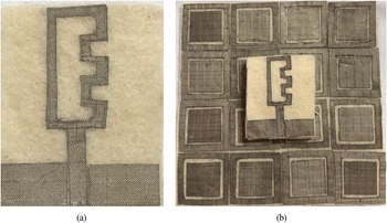
The fabrication process of the antenna was implemented using manual cutting tools. The fabric (shield) is cut to shape the monopole radiator and the ground plane. It is then affixed on the felt substrate by using heating. To prevent physical overlap/contact between the feed line and two rectangular grounds, a 0.2 mm gap was made between them. An SMA is connected to the feed line by using silver epoxy as soldering material. Figure 3(a) demonstrates the top view and Fig. 3(b) demonstrates the side view configurations of the proposed integrated antenna, respectively. Also, the proposed fabrication prototypes are portrayed in Figs 4(a) and 4(b).
Configuration of the E-shaped antenna: (a) top view of integrated design, and (b) side view of the integrated design; where L = 98.65 mm, W = 98.65 mm, h = 1.5 mm, d = 3 mm, H = 3 mm, Ws = 30, Ls = 37, Mo = 25 mm.

Prototype fabrication of the (a) E-shaped antenna, (b) E-shaped antenna integrated with a 4 × 4 AMC array.

Verification E-shaped antenna performance in free space
The E shape dual-band antenna is connected to a 50 Ω SMA connector [Reference Hamouda, Wojkiewicz, Pud, Kone, Bergheul and Lasri11], and it was created to work at 2.4 and 5.8 GHz frequencies. The following theoretical equations can be used to calculate the length of the E shape antenna design. The substrate's effective dielectric constant ɛeff is determined by (1):

By substituting the value of felt textile substrate dimensions ɛr = 1.2, h = 1.5 mm, and feed line width Wf = 3.4 mm into equation (1), to gives ɛeff = 1.139. Meanwhile, the first f 1 and second f 2 frequency band can be expressed in (2):

The speed of light is denoted by C, where λ 1 and λ 2 are the guide wavelengths for f 1 and f 2 resonant frequencies, respectively [Reference Pozar32]. The length l of the proposed E shape antenna for dual-frequency band f 1 = 2.4 GHz and f 2 = 5.8 GHz are related to λ 1 ≈ l and λ 2 ≈ 0.5l. However, the current path length of the E shape radiator is roughly equal to (3);

The optimal dimensions of the proposed E antenna are reported in the caption of Fig. 2.
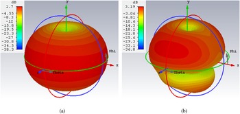
Figure 5 presents the reflection coefficient result of E-shaped antenna in free space with the measurement result on the VNA display screen; where the simulated is plotted by solid black and the measured is plotted by dotted red. A high agreement between both results is accomplished. Just a little shift is introduced in the measured curve this is due to the manual fabrication and the high flexibility of the substrate. The S11 of the antenna is below −10 dB within frequency bands from 2.22 to 2.68 GHz and from 5.45 to 6.13 GHz in the simulated result. While the measured results achieve a frequency band from 2.22 to 2.73 GHz and from 5.21 to 6.2 GHz respectively. The simulated 3-D gain pattern results at 2.4 and 5.8 GHz for monopole antenna are shown in Figs 6(a) and 6(b). The antenna has realized a gain of 1.7 and 3.19 dB with a total efficiency of −0.5413 and −0.9719 dB.
Reflection coefficient result of E-shaped antenna in free space, with a measured result on the VNA display screen.

Simulated 3D gain radiation pattern of the free space E-shape antenna (a) 2.4 GHz, and (b) 5.8 GHz.

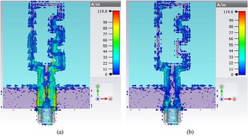
The current distributions of the E-shaped antenna are illustrated in Figs 7(a) and 7(b) at 2.4 and 5.8 GHz, respectively, at 0° phase obtained by using CST. The current distribution is presented in Fig. 7(a) has a current density with a high level in lines whose makes the resonance frequency at 2.4 GHz with a maximum current of 119.824 A/m. Figure 7(b) presents the current lines which make the resonance at 5.8 GHz at a maximum current of 114.633 A/m. It can be claimed that the antenna can be divided into two-part radiator; one part radiates for f 1 mode and the other for the f 2 mode, as shown in Figs 7(a) and 7(b). The feed line Lf has a common effect on both resonance frequencies.
Current surface distribution of the free space E-shape antenna at (a) 2.4 GHz, and (b) 5.8 GHz.

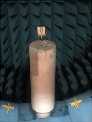
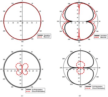
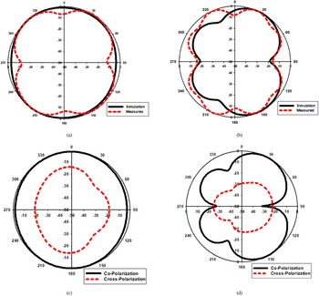
The measuring setup of the antenna inside the anechoic chamber is shown in Fig. 8, whereas Figs 9(a), 9(b), 10(a) and 10(b) show the normalized E-plane (X–Z plane) and H-plane (Y–Z plane) gains in free space (simulated result (solid black) and measured result (dotted red)), at 2.4 and 5.8 GHz respectively. The simulated and measured results are matched. However, certain discrepancies in the H-plane can be attributed to the constructed model's flexibility and soldering effect. While the co-and cross-polarized radiation patterns at 2.4 and 5.8 GHz for E-shape antenna without AMC are shown in Figs 9(c), 9(d), 10(c) and 10(d) respectively. As shown in these figures, a significant difference between co-polarization and cross-polarization results is achieved.
Setup for measuring the radiation pattern of the E antenna.

Simulated/measured normalized gain pattern of E-shaped antenna in free space at 2.4 GHz for (a) at φ = 0°, (b) at φ = 90°, (c) co-cross-polarization at φ = 0°, (c) co-cross-polarization at φ = 90.

Simulated/measured normalized gain radiation pattern of E-shaped antenna in free space at 5.8 GHz for (a) at φ = 0°, (b) at φ = 90°, (c) co-cross polarization at φ = 0°, (c) co-cross polarization at φ = 90°.

Verification of the E-monopole antenna on the human body
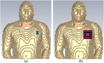
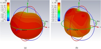
On the human body, the analysis is necessary because these devices operate very near to the body and hence loading effects might change the radiation properties and impedance matching of the antenna [Reference Abbasi, Nikolaou, Antoniades, Nikolić Stevanović and Vryonides33]. A real human has been used in several examples of on-body transmission study measurements. In [Reference Saied, Chandran and Arslan3, Reference Mendes and Peixeiro34, Reference Hamouda, Wojkiewicz, Pud, Kone, Bergheul and Lasri11], each of the analytical, numerical, phantom [Reference Simorangkir, Yang, Matekovits and Esselle8] or experimental, where the performance of several traditional antennas is assessed using real-life human measurements. The simulations are performed at the desired frequency. Therefore, the antenna prototype is placed on a human's chest, as present in Fig. 11(a). The S11 of simulation and measured are plotted versus frequency as present in Fig. 12, which includes the result on the VNA display screen. The antenna is added close to the human body at a distance of 2 mm and has a little effect on the matching and resonance. However, the antenna is still covering the required frequency band for WMBAN and the Wireless band. This proves the effectiveness of the proposed E-shaped antenna close to the lossy human body. As presented in Fig. 13, the radiated pattern of the monopole antenna is scarcely modified as a result of human chest interaction. Also, the gain of the antenna is decreased to 0.284 dB and 2.94 at 2.4 and 5.8 GHz, respectively.
Numerical human model (HUGO) in CST (a) E-shaped antenna, (b) E-shaped antenna integrated AMC.

Simulated/measured reflection coefficient result of E-shaped antenna without AMC on chest, with a measured result on the VNA display screen.

Simulated 3D gain radiation pattern of the E-shaped antenna on the phantom body at (a) 2.4 GHz, and (b) 5.8 GHz.

Dual-band AMC design
To enhance the antenna's performance in wearable applications and produce a low profile, high gain with unidirectional properties, and low SAR, the AMC structure can be utilized to work as a reflector. The AMC structure is essentially required as a reflector surface [Reference Mouhouche, Azrar, Dehmas and Djafri21] which makes a 0° reflection phase to an incident wave in a specifically required frequency band.
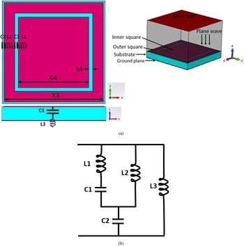
The geometry of the AMC unit cell with all dimensions is illustrated in Fig. 14(a). The AMC has an outer ring with an inner patch to produce the desired two frequency bands. The overall dimensions of the AMC unit cell are equal to 25 mm × 25 mm. The AMC unit cell is printed on the Felt substrate same as which used for the E antenna but with a thickness of 3 mm. The shieldIt superconductive layer is used as conductive material on the top and the bottom of the substrate.
(a) AMC unit cell layout with, X4 = 17.16.mm, X3 = 24.16 mm, M = 0.92 mm, (b) equivalent circuit model of AMC unit cell with, L1 = 1.12 nH, L2 = 1.67 nH, L3 = 0.737 nH, C1 = 0.56 pF, C2 = 1.47 pF.

To achieve a dual resonance frequency band, an outer square ring and inner square patch are added, where, the dimensions of the two squares are not the same, also the capacitances values are different.
The circuit model of the AMC unit cell is shown in Fig. 14(b) [Reference Pei, Leach, Lim, Wang, Song, Wang, Zhang, Jiang and Huang35]. By referring to the transmission line theory; the metal has inductance and the gap has capacitance. The inner square patch has a series inductance value L1 and C1 is caused due to the gap M between the inner square patch and the outer ring. The outer square ring has an inductance L2, and the capacitance C2 is created by the outer gap between the cell and others (inter-element). And the ground layer can model it as inductance L3, While the small capacitance C3 is caused by the substrate layer which is between the ground and upper patch, C3 can neglect it; due to it is small and common with all units. Meanwhile, the values of this inductance and capacitance are L1 = 1.12 nH, L2 = 1.67 nH, L3 = 0.737 nH, C1 = 0.56 pF, and C2 = 1.47 pF. By simulating this equivalent circuit with substitute these values of components in the advanced design system (ADS) program we get a high agreement between the reflection phase results of Electromagnetic full-wave simulation of AMC and circuit model simulation of AMC as shown in Fig. 15. However, the operation of the AMC is within the bandwidth extend between (−90° to +90°) and with 0o phase at 2.4 and 5.8 GHz respectively and these bands matched well with the circuit simulation. The phase difference between the EM/circuit simulator in the frequency band 7–8 GHz may be claimed as the accuracy of the EM solver was set to be high at a maximum frequency of 5.8 GHz to ensure good modeling. Another reason is the parasitic effect of distributed elements that represents the lumped elements in Fig. 14. These two reasons are enough to affect the phase difference given the phase is very sensitive.
Circuit/electromagnetic full-wave simulation of AMC.

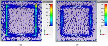
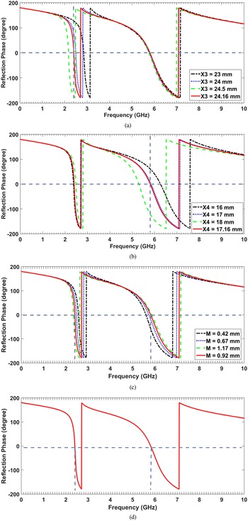
The inner patch has a resonant frequency of around 5.8 GHz, and the outer ring has a resonant frequency of reaching 2.4 GHz. The surface current follows the path of highest concentration on the outer square for 2.4 GHz, where the strong concentration is at the middle of the inner patch at 5.8 GHz, as shown in the blue cone in Figs 16(a) and 16(b). The reflection phase results of Electromagnetic full-wave simulation of the AMC unit cell design at varied values of X3, X4, and M are shown in Fig. 17. It has appeared that; when the length X3 is increased, the lower-band resonant frequency is decreased, while the upper-band resonant frequency is being constant as seen in Fig. 17(a), and when X4 is increased, the resonance frequency in the upper band is reduced as shown in Fig. 17(b). As well as, the gap between the outer and inner square can affect both lower and upper resonant frequency bands as present in Fig. 17(c). This means just by modifying the values of X3, X4, and M; the AMC's resonance frequency can be adjusted. Figure 14(a) shows the ideal design characteristics of the AMC unit cell at 2.4 and 5.8 GHz frequencies, and its reflector phase is presented in Fig. 17(d).
Simulated current surface distribution of AMC unit at (a) 2.4 GHz, (b) 5.8 GHz.

Dual-band AMC reflection phases for different values of (a) X3, (b) X4, (c) M, and (d) reflection phase of the proposed dimension.

E-shaped antenna integrated with AMC performance
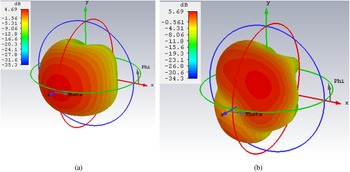
In this work, several AMC array sizes integrated with E-shaped antenna are tested to achieve the desired performance. The 4 × 4 array has achieved the optimum results. For an on-body link; AMC makes the radiation of the antenna perpendicular to the human body. However, without AMC, the radiation pattern of the monopole antenna is omnidirectional which produces a high SAR level that affects the human body. Also, instead of using another antenna to send the data to the doctor in the hospital; this high gain antenna can achieve this task without affecting the human body by reducing the SAR level by 95%. So, this antenna can be used in both communications. The 4 × 4 array has achieved the optimum results with a gain level equal to 4.69 and 5.69 dB at the desired frequency bands.
One of the main functions of the integrated AMC array is to reduce the back radiation by reflecting electromagnetic waves in some specific frequency bands, which is led to decrease the SAR values when loaded with the human body at both 1 and 10 g as present in Figs 21 and 22 where these values listen in Table 1.
Values of SAR with and without integrated AMC.

From the results shown in Figs 21, 22, and Table 1. We can conclude that; the suggested antenna has a SAR level lower than the American standard limit which is 1.6 W/kg averaged over 1 g of tissue, and the European standard limit which is 2 W/kg averaged over 10 g of tissue. However, the antenna was suggested to be operated in the biomedical application which needed to wearing the antenna for a long and continuous period, for that it has to be lower, and the lower the better, than those limits to ensure human body safeness; especially it is close to the heart to no effect on the electricity of the heart.
Another important function of the integrated AMC array is to enhance the gain [Reference Mouhouche, Azrar, Dehmas and Djafri21]; as shown in Table 2. below which is a comparison between the proposed antenna design with and without integrated AMC on body cases in terms of simulated realized gain and total efficiency. Also, the AMC converts the radiation pattern from an omnidirectional form to a directional radiation pattern.
Values of gain and total efficiency of an antenna with and without integrated AMC.

Verification of E monopole antenna loaded with AMC reflector in free space
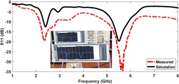
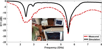
An array of 4 × 4 AMC, which was shown in Fig. 3, is designed to serve as a reflector for an antenna. The AMC was arranged in a way that gets the reflection phase of the array to fall in the required band. The gap between the elements is fixed at the optimal value of 0.42 mm obtained in the last section. This gives an overall array dimension of 98.65 × 98.65 mm2. Figure 18 presents the S11 simulated and measured results of the E-shaped antenna integrated with a 4 × 4 AMC array in free space, which includes the measurement result on the VNA display screen. Where the result shows well agreement between simulated and measured with only some shifts appear; that is due to the manual fabrication tolerance or may be caused by the external effects during the measurements. A monopole antenna is designed by incorporating the AMC 4 × 4 array as a reflector. The AMC array is placed at a distance of 3 mm, under the proposed E-shaped antenna. A 3 mm thick foam layer is used between them. The E-shaped antenna with AMC surfaces achieves directional radiation pattern, antenna gain enhancement, and bandwidth improvement to increase the system performance.
Simulated/measured reflection coefficient result of E-shaped antenna integrated with AMC in free space, with the measured result on VNA display screen.

The S11 of simulation and measurement of E-shaped antenna integrated with AMC in free space are plotted versus frequency as present in Fig. 18, which includes the result on the VNA display screen. Where the simulated gains of an E-shaped antenna integrated with AMC in free space at the desired two frequency bands are depicted in Figs 19(a) and 19(b). The gain increased from 1.7 to 3.19 dB (without AMC) to 4.69 and 5.69 dB (with AMC), respectively.
Simulated 3D gain radiation pattern of the E monopole antenna integrated with AMC on free space (a) 2.4 GHz, and (b) 5.8 GHz.

Verification of the E-shaped antenna with AMC reflector on the human body
Due to the suggested E-shaped antenna integrated with the AMC array would be worn, the effectiveness of the human body on the performance of integrated design was investigated through modeling and experiment. The phantom model on the CST program was used for simulation and the real human body for measurement. The design was tested by placing it at a space of 2 mm from the chest, by assuming the human clothes have 2 mm thickness. The simulations are run at the desired two frequency bands, and a prototyped antenna with integrated AMC is mounted on a human's chest, as shown in Fig. 11(b). The S11 simulation and measured results of the E-shaped antenna integrated with AMC on the human body (chest) are present in Fig. 20 with the measurement result as on the VNA display screen. A little decrease in the matching was occur; that's due to the manual fabrication and external equipment. Also, when the antennas operate close to the body, the matching and resonant frequency can be affected [Reference Yan, Soh and Vandenbosch36].
Simulated/measured reflection coefficient result of integrated E-shaped antenna with AMC on the human body, with a measured result on VNA display screen.

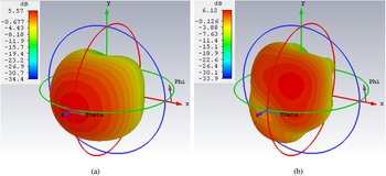
Figure 21(a) and 21(b) show the simulated gains at two frequency bands, which are equal to 5.57 and 6.12 dB, respectively.
Simulated 3D gain radiation pattern the phantom with 4 × 4 AMC at (a) 2.4 GHz, and (b) 5.8 GHz.

SAR analysis
The amount of radiation energy that is absorbed by the human body when it is exposed to a radiofrequency electromagnetic field can be defied by specific absorption rate (SAR) which has a unit of watts per kilogram (W/kg), where it is the amount of energy absorbed by the human body per mass of tissue and is averaged over a small sample volume (typically 1 g or 10 g of tissue). The value of SAR can be evaluated by (4).

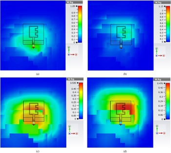
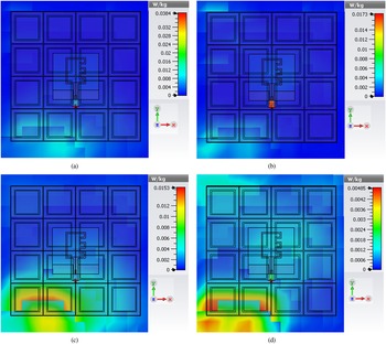
The electric field (V/m), the tissue's conductivity (S/m), and tissue's mass density (kg/m3) are denoted by E, σ, and ρ respectively. The SAR readings must not exceed the absorption rate of 1.6 W/kg averaged over 1 g of human body tissue [37] and 2 W/kg absorbed per 10 g of human body tissue [Reference Afridi, Ullah, Khan, Ahmed, Khalil and Tarar38]. The voxel data set has been segmented and classified into 40 distinct types of tissues and is available at 8 × 8 × 8 mm mesh size. The antenna is placed in front of the human model's chest. Rather than modeling the entire numerical model, which requires a big computer memory size and a long time, an appropriately sized area of the chest is picked to save simulation time. In addition, the number of mesh cells has been lowered to 38 162 688 mesh cells, resulting in a significant reduction in simulation time. The SAR analysis of AMC integrated antenna and antenna without AMC with a space of 2 mm above the human chest are investigated. Meanwhile, the antenna design and distance have significant effectiveness on the SAR value. The input power of 0.1 W was chosen because in general; the devices operate at this power level in the WMBAN band. The simulated SAR of the antenna was done at both 1 and 10 g averaging mass, at both 2.4 and 5.8 GHz with and without AMC. The suggested antenna design without AMC achieved SAR values 1.09 and 0.535 W/kg at 1 and 10 g at 2.4 GHz respectively as shown in Figs 22(a) and 22(c). While it achieved values equal 1.13 and 0.476 W/kg at 1 and 10 g at 5.8 GHz as shown in Figs 22(b) and 22(d). However, in both bands, the antenna is proved their resilient against the impact of human body loading with a lower effect on the body and a low SAR which is below the allowed SAR levels by the FCC. However, for more safety, the levels should be reduced lower than these values. The integrated E-shaped antenna with AMC has a SAR value of 0.0384 and 0.0153 W/kg at 1 and 10 g respectively for 2.4 GHz as shown in Fig. 23(a) and 23(c). While it achieved values equal 0.0173 and 0.00485 W/kg at 1, and 10 g for 5.8 GHz as present in Figs 23(b) and 23(d). As a result, the suggested antenna design with AMC achieved a significant reduction in SAR and high antenna gain.
Simulated SAR of the E-shaped antenna at, (a) 2.4 GHz 1 g, (b) 5.8 GHz 1 g, (c) 2.4 GHz 10 g, (d) 5.8 GHz 10 g.

Simulated SAR of the proposed integrated E-shaped antenna at, (a) 2.4 GHz 1 g, (b) 5.8 GHz 1 g, (c) 2.4 GHz 10 g, (d) 5.8 GHz 10 g.

Table 3 shows the comparison between our proposed design and other wearable antenna design in the literature, this comparison proves that the proposed design met good specifications for wearable antenna as low profile and flexibility and the compact size and space between antenna and AMC. Also, our proposed design achieved a very low SAR value.
Comparison between different biomedical wearable antenna design.

Conclusion
The E-shaped dual-band monopole antenna designed from flexible textile and has a low profile has been proposed in this work. The proposed E-shaped antenna has been integrated with dual-band textile AMC operating at 2.4 and 5.8 GHz for health monitoring applications. In terms of all the results presented, the proposed E-monopole antenna with and without integrated AMC close to the human body has been met the American and European SAR standards.
 Farah R. Kareem was born in 1992. She received a B.Sc. in electrical engineering from the Electronic and Communication Engineering Department, MSA University, Egypt in 2014 and M.Sc. degree in electrical engineering from the Electronic and Communication Engineering Department, Arab Academy for Science, Technology and Maritime Transport, Cairo, Egypt in 2018. And now studying Ph.D. in electrical engineering from the Electronic and Communication Engineering Department, Minia University, Elminia, Egypt since 2020. She is now a lecturer assistant in the Electrical Engineering Department in the Faculty of Engineering MSA University.
 Mohamed El Atrash received the B.Sc. (with honors) in electrical engineering from the Electrical Systems Engineering Department, October University for Modern Sciences and Arts (MSA), Cairo, Egypt, in 2011. He also received the M.Sc. degree (with distinction) in wireless mobile communications systems engineering from the University of Greenwich (UoG), United Kingdom, in 2014. In 2020, he successfully completed his Ph.D. degree in electrical engineering at Ain Shams University, Cairo, Egypt. His research interests include flexible wearable antennas, high gain, thin, low-profile antennas, and EBG/AMC design. Out of his research, he published articles in the IEEE Transactions on Antennas & Propagation, IET Microwaves, Antennas & Propagation, International Journal of Microwave and Wireless Technologies, and IEEE Access, as well as, a number of conference papers. He is a reviewer in the IET Microwaves, Antennas & Propagation, since 2019, where he has reviewed more than 15 journals. He also reviewed Microwave and Optical Technology Letters, AEUE-International Journal of Electronics and Communications, and International Journal of RF and Microwave Computer-Aided Engineering.
 Ahmed A. Ibrahim was born in 1986. He received the B.Sc. degree, and M.Sc., Ph.D. in electrical engineering from the Electronic and Communication Engineering Department, Minia University, Elminia, Egypt in 2007, 2011 and 2014 respectively. He is now an associate professor in the Electrical Engineering Department in The Faculty of Engineering at Minia University. He has been a visiting professor at University Pierre and Marie Curie, Sorbonne University, Paris VI, France for 7 months and Otto-von-Guericke-Universität Magdeburg-Germany for 6 months. He has published more than 70 peer-reviewed journals and conference papers. His research has focused on miniaturized multiband antennas/wideband, microwave/millimeter components, DRA metamaterial antenna, graphene antenna and microwave filters. Also, his research includes MIMO antennas and energy harvesting systems. Dr. Ahmed A Ibrahim is a senior member of the IEEE and a senior member in URSI also a member in the national committee of radio science in Egypt. He is currently a reviewer in, IEEE Antennas and Wireless Propagation Letters, IEEE Microwave Wireless Components, IEEE access, IET Microwave, Antenna and Propagation, IET Electronics Letters, MOTL, Analog Integrated Circuits and Signal Processing and many other journals and conferences.
 Mahmoud A. Abdalla was born in 1973. He received a B.Sc. degree, in electrical engineering from the Electrical Engineering Department, Military Technical College, Cairo, Egypt in 1995. He was awarded the M.Sc. degree, in electrical engineering from Military Technical College in 2000, and the Ph.D. degree from Microwave and Communication Group, School of Electrical Engineering, Manchester University, UK, in 2009. He has been with Military Technical College since 1996 where he is now a professor, the head of the Department Council Committee and also the electromagnetic waves/microwave group in the Electronic Engineering Department. Also, he has been a visiting professor in the Department of Computer and Electrical Engineering, University of Waterloo, Canada since 2017. Prof. Abdalla is currently a senior member of the IEEE since 2015, URSI since 2020 and the European Microwave Association EuMA since 2011. He is a recognized international authority in the society of electromagnetics. He has published more than 200 peer-reviewed journal and conference papers. His research is focusing on miniaturized multiband antennas/wideband microwave/millimeter components and antennas with great attention is to employ metamaterial/EBG, structures, MIMO antennas, energy harvesting systems, smart antennas, frequency selective surfaces, radar absorber and electromagnetic launchers. He is currently an editor and a reviewer in many electromagnetic journals such as IEEE Transactions on Antenna and Propagation, IEEE Antennas and Wireless Propagation Letters, IEEE Transactions in Microwave Theory & Techniques, IEEE Microwave Wireless Components Letters, IEEE Transactions in Magnetics, IET Microwaves, Antenna and Propagation, IET Electronics Letters, IET Communications, Microwave and Optical Technology Letetrs, International Journal of Microwave and Wireless Technologies, Scentific Reports, AEU International Journal of Communication and Electronics, Personal Wireless Communication and others. Prof. Abdalla served in the technical committee of many conferences in the areas of electromagnetic/electronic and communication. Prof. Abdalla was the recipient of Egyptian encouragement state prize award for engineering sciences in 2014. In 2019, he was the recipient of Egyptian El-sherouq innovation award in electronic engineering. He was awarded the top 1% Publon worldwide reviewer award for 2018 and 2019. In 2020, he was named in the top 2% of scientists in “A standardized citation metrics author database annotated for scientific field”/“Updated science-wide author databases of standardized citation indicators”.