


I. INTRODUCTION
The direct-conversion radio architecture, which is based on complex in-phase and quadrature (I/Q) up- and downconversions, is the current choice in building low-cost yet flexible and efficient radio transceivers [Reference Mak, Seng-Pan and Martins1]. There are, however, several practical implementation-related problems still ahead before the direct-conversion principle can be successfully deployed to process more complex wideband waveforms of future wireless systems [Reference Fettweis, Löhning, Petrovic, Windisch, Zillmann and Rave2]. These problems are stemming from imperfections and non-idealities of the used radio frequency (RF) and baseband electronics, such as I/Q mismatch, oscillator phase noise, signal leakages in the local oscillator (LO) resulting in DC offsets and even-order nonlinear distortion, and power amplifier (PA) nonlinearities. The effects of these impairments are becoming more pronounced as higher-order modulated waveforms and/or more wideband multi-channel signals are used. In multiple-input multiple–output systems the problems are expected to be even more severe, since each antenna has its own radio transceiver, and thus its own independent impairments [Reference Zou, Valkama and Renfors3]. Furthermore, the extremely wide bandwidths and signal dynamics expected to be supported by future cognitive radio terminals necessitate adaptive means to cope with circuit impairments. Therefore, high-performance adaptive digital calibration and signal enhancement methods, suitable for a wide range of wideband waveforms, will be needed in future wireless transceivers [Reference Fettweis, Löhning, Petrovic, Windisch, Zillmann and Rave2].
The PA is one of the key components of a transmitter. The PA is responsible for amplifying the transmitted signal such that it arrives at the receiver with sufficient power level for successful detection. Maximizing the power efficiency of the PA is an important issue, especially at the terminal side, in order to maximize battery life and minimize generated heat. For maximum efficiency, the PA needs to be operated in the nonlinear region, as close to saturation as possible. With modern signal waveforms with high peak-to-average power ratio (PAPR), plenty of nonlinear distortion, both harmonic and intermodulation distortion, will be created [Reference Fettweis, Löhning, Petrovic, Windisch, Zillmann and Rave2, Reference Katz4, Reference Kim5]. In the frequency domain this nonlinear distortion is seen as spectral regrowth, wherein a great deal of power can be leaked onto the adjacent channels. Many types of PA linearizers – devices or techniques that try to make the PA response linear – have been proposed and used in the past (see [Reference Katz4] for a review). From performance and flexibility points of view, adaptive digital predistortion is currently seen as the most promising linearization technique [Reference Kim5]. In this article, when speaking of predistortion (PD), we mean adaptive digital PD.
Relative amplitude and phase mismatches between the in-phase and quadrature signal branches of direct-conversion radios cause mirror-frequency interference (MFI) [Reference Fettweis, Löhning, Petrovic, Windisch, Zillmann and Rave2]. In transmitters, depending on the spectral content of the low-frequency I and Q signals (baseband or low-IF), MFI results in self-interference or adjacent channel interference. In addition to this problem, I/Q imbalance and LO leakage are known to weaken the performance of adaptive PA predistorters [Reference Cavers6, Reference Cavers7]. Under I/Q imbalance and/or LO leakage, the PA predistorter coefficient estimates become biased and PD can, in some cases, even worsen the spectral regrowth.
Some authors have considered these implementation problems together previously. The techniques in [Reference Cavers7–Reference Anttila, Valkama and Renfors9] focus on I/Q modulator/demodulator errors only, not assuming any specific PA predistorter. In [Reference Huang and Caron10], a simple polynomial PA predistorter is added to complement the modulator predistorter. Unfortunately, due to the separate processing of the PA and modulator impairments, refs. [Reference Cavers7–Reference Huang and Caron10] require considerable extra RF hardware compared to pure PA PD in the form of either an RF switch or a second feedback loop. The methods in [Reference Kim, Jeong and Lee11, Reference Hilborn, Stapleton and Cavers12] are truly joint methods, i.e., they estimate all the impairments jointly, without the need for extra RF hardware. However, they only consider frequency-independent impairments. In [Reference Cao, Tehrani, Fager, Eriksson and Zirath13], a Volterra-based predistorter was developed for nonlinear I/Q imbalance, but the sources of nonlinearity were in the baseband I/Q components, and the PA was not included in the developments. Thus currently, there is no technique available for estimating and compensating frequency-dependent PA and modulator impairments jointly. Altogether handling of frequency-dependent RF impairments is seen critical for the emerging wireless systems, like IMT-Advanced, in which radio bandwidths in the order of 10–100 MHz will be deployed.
This article is an extension of [Reference Anttila, Händel and Valkama14], where the joint predistorter structure for frequency-dependent PA and I/Q modulator calibration has been initially introduced by the authors. There, a conventional block-based least-squares (LS) training approach was used, utilizing the indirect learning architecture (ILA). Now, we propose a recursive implementation of the predistorter. Moreover, we introduce a modified and more efficient learning strategy, where the predistorter is updated more frequently compared to traditional indirect learning with block-based LS estimation. The proposed approach will be able to better follow time-varying changes in the characteristics of the front-end, as well as be more amenable to practical transmitter digital front-end implementations using e.g. field-programmable gate arrays (FPGA). The proposed technique is the first technique that considers all the major analog impairments of a wideband direct-conversion radio transmitter in a joint manner, enabling one-step estimation of the predistorter parameters without any extra RF hardware. Simulation and measurement analyses show superior performance compared with state-of-the art. The proposed technique can find applications especially in cellular base-stations, broadcast transmitters, and other high-performance RF signal generators.
The article is organized as follows. Section II introduces the novel predistorter structure for PA and modulator impairments, especially tailored for frequency-dependent impairment calibration and efficient parameter identification. Then, in Section III, an efficient recursive LS-based parameter estimation technique for calculating the predistorter coefficients is proposed, utilizing the ILA. Experimental results are presented in Section IV, and Section V concludes the article.
Notation: Vectors are in bold lower-case and matrices in bold upper-case. Complex conjugation, matrix transpose, and conjugate transpose are denoted by (·)*, (·)T and (·)H, respectively. The statistical expectation operator is E[·].
II. JOINT PA AND I/Q MODULATOR PD
A general I/Q modulator-based transmitter structure, including the digital predistorter in the serial configuration (as in [Reference Ding, Ma, Morgan, Zierdt and Zhou8], for example), is shown in Fig. 1. This structure compensates for the impairments in the reverse order that they appear, and is used as the starting point here. The PA predistorter is a parallel Hammerstein (PH) or memory polynomial predistorter with the static nonlinearities given by the polynomials

with x n = x n,I + jx n,Q denoting the baseband I/Q signal, P the polynomial order, I P the set of used polynomial orders, and u k,p the polynomial weights [Reference Ding15, Reference Isaksson, Wisell and Rönnow16]. If all polynomial orders up to P are used in (1), I P = {1, 2, 3, … , P}, and if only odd orders are included, I P = {1, 3, 5, … , P}. The subset of I P in which orders only up to p are retained, is denoted by I P;p. The filters H p(z), in turn, are usually finite impulse response filters for implementation and parameter estimation simplicity. The PH model has been generally shown to be a versatile tool for inverse as well as direct modeling of PAs [Reference Isaksson, Wisell and Rönnow16]. One may also note that direct and inverse PA models have similar properties [Reference Isaksson and Rönnow17].
General I/Q modulator-based transmitter structure including the adaptive digital predistorter in serial configuration [Reference Anttila, Händel and Valkama14].

The polynomial in (1) is general, including both even and odd polynomial orders, and enabling the use of either conventional polynomials (by setting u k,p = 0, k ≠ p) or some type of orthogonal polynomials. In this article, the statistically orthogonal polynomials (meaning that for p ≠ q, E[ψp(x n)*ψq(x n)] = 0) for complex Gaussian signals from [Reference Raich and Zhou18] are adopted. Other polynomials, orthogonal or not, can be used as well, but their numerical properties may be different. The reader is referred to [Reference Raich and Zhou18] for a discussion of the possible numerical difficulties encountered in PD parameter estimation.
The I/Q predistorter in the serial PD is of the general two-filter type (see, e.g., [Reference Ding, Ma, Morgan, Zierdt and Zhou8, Reference Anttila, Valkama and Renfors9]), where one filter, G 1(z), is filtering the original or non-conjugate signal, and the other filter, G 2(z), is filtering the conjugated signal. The actual baseband I/Q imbalance model has a similar, so-called widely linear, form, with filters H 1,TX(z) and H 2,TX(z) filtering the non-conjugate and conjugate signals. These I/Q imbalance filters can, without loss of generality, be expressed as H 1,TX(z) = (1 + g exp(jϕ)H(z))/2 and H 2,TX(z) = (1 − g exp(jϕ)H(z))/2, where g, ϕ, H(z) denote the amplitude, phase, and impulse response mismatch of the transmitter front-end, respectively [Reference Anttila, Valkama and Renfors9]. For complete MFI removal, the compensator filters are related to the imbalance filters formally as G 1(z) = kH* 1,TX(z*) and G 2(z) = −k*H 2,TX(z), where k is an arbitrary (non-zero) constant.
The serial PD structure depicted in Fig. 1 is conceptually feasible but in practice problematic from the parameter estimation point of view. The filters of the PA PD and I/Q PD are in cascade, making their joint estimation difficult. With the serial structure, one has to train the predistorters separately, requiring additional RF hardware compared to pure PA PD. In [Reference Anttila, Händel and Valkama14], we proposed a modified PD structure which is completely parallel, enabling one-step estimation of all PD parameters using linear LS, and without any extra hardware.
The joint PA and modulator predistorter structure, proposed in [Reference Anttila, Händel and Valkama14], is shown in Fig. 2. The filters in Fig. 2 are formally given as F p(z) = H p*(z*)G 2(z) and  , for p ∈ I P. Thus, the predistorter is a parallel connection of two PH nonlinearities, given as

and

Parallel widely linear conjugate predistorter structure for the joint PD of frequency-dependent PA and I/Q modulator impairments (from [Reference Anttila, Händel and Valkama14]).

Here, f p,n and  are the (complex-valued) impulse responses of F p(z) and
 , respectively, I Q is the set of used polynomial orders for the conjugate PD (defined similarly as I P), and
 denotes convolution. Notice that in (2b) the polynomial order is now changed to Q, since in general the orders in (2a) and (2b) need not be the same. Finally, taking into account the LO leakage compensator c′, we can write the output of the complete predistorter as

The LO leakage compensator c′ in the parallel structure is a transformed version of the original (serial) compensator c, as it is moved to the other side of the I/Q imbalance compensator when derivating the final PD structure.
Notice that if Q = P, the final predistorter structure in Fig. 2 is equivalent to the original serial structure in Fig. 1. However, in the general case (with Q ≠ P), the derived structure gives indeed additional degrees of freedom in the predistorter design, compared to the serial structure, being able to have different processing orders (polynomial orders and amount of memory) for the direct and conjugate signal terms.
The dimensionality of the parallel PD is, in terms of complex-valued parameters, roughly 1.5- to 2-fold compared to the serial PD [Reference Anttila, Händel and Valkama14]. This implies higher computational requirements in both estimation and actual PD stages, as discussed in detail in [Reference Anttila, Händel and Valkama14]. The number of floating point operations in the estimation stage is about four times greater with the parallel structure. In the PD stage, the aforementioned 1.5- to 2-fold increase in complex-valued multiplications compared to the serial structure is seen. However, the serial structure is not identifiable, unless separate training of the two PDs, and the necessary additional hardware, are employed. In contrast, the proposed parallel structure is guaranteed to be identifiable (under certain non-restrictive assumptions on the PA and the PA input signal), due to the linearity with respect to its parameters, without additional hardware.
III. PREDISTORTER PARAMETER ESTIMATION
A) Indirect learning
In the parameter estimation stage we utilize the ILA, which enables the estimation of the predistorter coefficients directly, without the need for finding and inverting a PA model, and by using linear LS methods. The idea behind the ILA is to find the post-inverse of the PA nonlinear function and then, assuming that it equals the pre-inverse, use it as the predistorter. Schetzen [Reference Schetzen19] showed that for an invertible Volterra nonlinearity the pth-order pre-inverse is equal to the post-inverse, thus giving a formal justification to the ILA principle. Further discussion and details on indirect learning can be found, e.g., in [Reference Ding, Ma, Morgan, Zierdt and Zhou8, Reference Raich and Zhou18, Reference Eun and Powers20, Reference Morgan21] and the references therein. The principal operation of the ILA is illustrated in Fig. 3. Here, H(·) denotes the PA nonlinear function, and  is the estimate of the post-inverse of H(·). Ideally,
 , with G denoting the intended (amplitude) gain of the amplifier.
The ILA operating principle.

In this article, we define an ILA iteration as a single cycle of the following operations:
1) transmitting a predistorted signal of length N (in the first ILA iteration the predistorter is turned off),
2) measuring the signal in the feedback loop and identifying the post-inverse of the PA, and
3) plugging the post-inverse parameter estimates into the predistorter.
The postdistorter coefficients in the identification step 2) are found as a solution to a selected optimization criterion, such as minimizing the LS error or mean-square error between postdistorter output and the reference signal.
An interesting feature of the ILA is, that several such ILA iterations may be needed for the predistorter to fully converge, as noted for example in [Reference Raich and Zhou18, Reference Morgan21]. This phenomenon is due to the dynamic and nonlinear nature of the estimation problem: certain properties (namely bandwidth and PAPR) of the predistorted signal change upon each PD update, until the PD has completely converged [Reference Anttila, Händel and Valkama14]. These changes are most notable after the first ILA iteration, when the first estimated parameters are plugged into the PD.
B) Block LS estimation
With reference to Fig. 3, we denote the postdistorter input signal (the complex envelope of the scaled PA output) by s n, the postdistorter output signal by ẑ n, and the training signal length by N. Assuming finite time spans for the filters f p,n and  , denoted, respectively, by L p and
 , we can write the postdistorter output signal (3) in vector–matrix notation as

Above, the filter impulse response vectors are given as


and the filter input vectors are obtained from (1) as


Notice that f1 and  are the linear filters of the predistorter, with respective lengths L 1 and
 , whereas fp and
 , p > 1 are the polynomial filters.
Collecting a block of N samples of the observed signal s n, we can write the output vectors of the pth non-conjugate and qth conjugate predistorter branches as


Here Ψp is the non-conjugate polynomial basis matrix of order p, given as
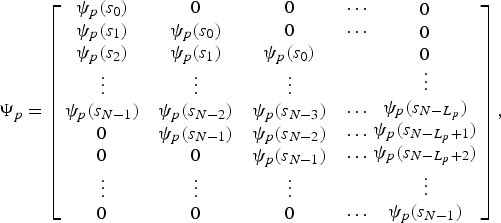
and  is the conjugate polynomial basis matrix of order q, constructed in a similar manner. The matrix Ψp has dimensions (N + L p − 1) × L p, and similarly
 has dimensions
 .
Then, we add zero rows to the bottom of all Ψp and  to make them of equal height. By collecting all the polynomial basis matrices into a single block matrix, and appending it with a vector of all-ones 1 to account for the LO leakage compensator, we obtain the complete data matrix

Finally, stacking the filter impulse responses of (5a) and (5b) and the LO leakage compensator coefficient into a single vector as

we can write the complete postdistorter output vector as

Using (5)–(11), and denoting the corresponding reference signal vector by z , the LS estimation problem is constructed as finding that parameter vector
 which minimizes the cost function J(f) = ‖z − ẑ‖Reference Fettweis, Löhning, Petrovic, Windisch, Zillmann and Rave2, yielding the well-known LS solution [Reference Haykin22]

In practical implementations, numerical methods like singular value decomposition can be used to implement the pseudo-inverse (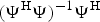 ) calculations in (12).
C) Recursive LS solution
The block solution described above may not be the best choice for learning time-varying parameters, such as the proposed predistorter. Time-dependent impairment characteristics may in practice results, e.g., from temperature changes in the operation environment or device aging. Furthermore, practical FPGA implementations are not well equipped to handle large block LS solutions, especially in terms of matrix inverse or pseudo-inverse calculations, but are more at home with recursive real-time learning algorithms. Thus, the recursive LS (RLS) algorithm is a natural choice for the estimation stage here.
We now follow the notations in Fig. 3 as well as in the above batch solution, and denote the iteration index inside the RLS iteration by i,i = 1, 2, …,N. A single update cycle of the recursive learning rule can then be formulated as

Here v(i) = Ψ(i,:) denotes the ith row of the previous data matrix Ψ in (9), f(i) denotes the pre-distortion parameter vector estimate at iteration i, d(i) = z i−1 denotes the reference signal value at iteration i, and finally λ is the internal memory or averaging parameter of the recursion. For general discussions on recursive learning rules, refer e.g. to [Reference Haykin22].
Here, when combining the indirect learning principle and the recursive LS learning rule, there are basically several different possibilities how to map the parameters between the post-inverse modeling and the actual PD stage. One feasible approach, as was proposed in the first ever paper to consider the ILA in PA PD identification [Reference Eun and Powers20], is to estimate and update the predistorter continually, at each RLS iteration. However, this approach has some drawbacks. The inevitable delay in updating the PD (resulting from the delay between transmitting the data samples and receiving them in the feedback loop, including all digital and analog delays) will lead to slower convergence of the algorithm, and can, in principle, even cause instability. The slower convergence will be illustrated in a simulation example in Section IV. Another practical difficulty is, that a prototype setup for a real-time updating algorithm is difficult to construct.
We propose a block-adaptive approach for learning as follows. First, start with pre-distortion set off (f(0) = 0) and apply the recursive learning approach over a time window of N samples. After this, the learned pre-distortion parameters  are deployed to actually pre-distort the transmit (reference) data and a new period (new ILA iteration) with recursive learning is deployed. At each ILA iteration, the parameter vector from the previous ILA iteration is used as the initial point in RLS learning. Furthermore, the matrix M(i), which is essentially the inverse of the input vector correlation matrix, can be either initialized with a suitable diagonal matrix at each ILA iteration, or retained between successive ILA iterations. Intuitively, it may be advantageous to reset M(i) between ILA iterations until the parameters have converged, i.e., for the first two to four ILA iterations, and after that to keep M(i) between ILA iterations. These steps effectively combine the indirect learning principle and recursive learning rules such that efficient parameter identification is obtained. This will be demonstrated in Section IV using both computer simulations as well as laboratory radio signal measurements.
D) Practical aspects
1) Measurement noise
So far, the feedback signal has been assumed noiseless. In practice, however, there is inevitable circuit and quantization noise in the feedback signal. Contrary to an ordinary LS problem where the noise would lie in the reference vector z, in the current inverse modeling problem the measurement noise lies in the data matrix Ψ. This kind of an estimation problem is called a data least-squares (DLS) problem [Reference DeGroat and Dowling23], or an errors-in-variables model [Reference Griliches and Ringstad24]. As is well known in the statistical literature and also shown in [Reference Anttila, Händel and Valkama14], applying LS estimation to a DLS problem will induce a bias to the parameter estimates. Fortunately, due to the transmitter internal processing, feedback noise levels are low, with signal-to-noise-ratios (SNR) in excess of 50 dB being quite easily obtainable in practice.
2) Memory effects
PAs typically suffer from two kinds of memory effects (MEs): short-term MEs and long-term MEs. The short-term MEs typically arise from the PA's input and output matching networks, and involve time constants in the order of the period of the carrier. Long-term MEs, on the other hand, are low-frequency phenomena, ranging in period from DC up to kHz or MHz range. They are mainly attributed to PA biasing networks and thermal effects. The proposed PD structure is able to handle short-term MEs, but in the current setup, is not equipped to deal with long-term MEs. This forms an interesting and important topic for further studies.
3) Synchronization
One of the main practical problems in implementing any adaptive predistorter is the requirement of very accurate time and frequency synchronization of the feedback signal. If both the upconverting and downconverting LO signals are derived from the same clock, as is the case usually, dedicated frequency synchronization is needless. Time synchronization, on the other hand, is more problematic, since the loop time delay can only be known nominally beforehand. Thus, an efficient algorithm, capable of providing timing accuracy within about 1% of the sample interval, is required. In the measurements conducted for this article, the discrete Fourier transform-based time-delay estimator outlined in [Reference Nentwig25] was used.
IV. Simulation and measurement examples
In the previous sections, we have introduced a novel predistorter structure for the joint compensation of PA and I/Q modulator impairments, and proposed recursive LS-based learning rule for parameter estimation utilizing the ILA. Next, we assess the performance of the proposed solution through extensive computer simulations and laboratory measurements, and compare it with state-of-the-art techniques. The reference techniques used in the simulations and measurements are the plain PH PD without I/Q mismatch compensation (see, e.g., [Reference Ding15]) and the memoryless joint PA/IQ PD from [Reference Kim, Jeong and Lee11]. These essentially represent state-of-the-art in the field. The chosen figure-of-merit is the adjacent channel power ratio (ACPR), defined as

with S(ω) denoting the power spectral density (PSD) of the transmit signal s n, and ωA and ωD the frequency band of the (worse) adjacent channel and the desired channel, respectively. Definition (14) assumes that the desired channel and adjacent channel have equal bandwidths. It is worth noting that there is a difference in adjacent channel content between the direct conversion and the low-IF transmitters; in direct conversion, the adjacent channel power consists only of spectral regrowth due to (remaining) PA nonlinearity, while in the low-IF case it also includes the MFI resulting from I/Q imbalance, and possibly also the tone due to LO leakage.
In the following simulations, two different PA models are employed. One is a Wiener system, meaning that there is a linear time-invariant filter followed by a static nonlinearity. The Wiener PA parameters are from [Reference Ding26], and have been reportedly extracted from a real class AB PA. The filter has transfer function (1 + 0.3z −2)/(1 − 0.2z −1), while the static nonlinearity is a fifth-order polynomial with complex-valued coefficients a 1 = 14.9740 + 0.0519j, a 3 = −23.0954 + 4.9680j, and a 5 = 21.3936 + 0.4305j. The other PA model is a Rapp solid-state amplifier model with smoothness factor p = 1.5 [Reference Rapp27].
The I/Q imbalance parameters are the same in all simulations, and are as follows: gain imbalance 5%, phase imbalance 5°, and impulse response mismatch h TX = [1, −0.035]T (for more details on the I/Q mismatch model, refer to [Reference Anttila, Valkama and Renfors9]). These imbalance values represent a realistic practical scenario from the radio electronics point of view.
A) Simulation example 1 – OFDM direct-conversion Tx
The example waveform used in the first simulation is an OFDM signal built according to the 3GPP long-term evolution (LTE) specifications' [28] 10 MHz mode, with 600 active subcarriers out of 1024, and with subcarrier spacing of 15 kHz. The signal is oversampled four times and low-pass filtered to attenuate the spectral sidelobes, before transmission. The PA model is the Wiener model described above. Due to the high PAPR of the OFDM waveform, the PA input power is backed off 5 dB from the PA's 1-dB compression point. As a practical example with feasible implementation complexity, the used PD consists of a ninth-order PD for the non-conjugate and a fifth-order PD for the conjugate signal. Both PDs are PH with branch filter lengths L p = 5, 5, 4, 4, 3 for p = 1, 3, 5, 7, 9, and L q = 5, 4, 3 for q = 1, 3, 5, respectively. The orthogonal polynomials from [Reference Raich and Zhou18] are utilized. Including also the LO leakage compensator, there are altogether 34 complex coefficients to estimate. At each ILA iteration, 500 RLS recursions are used for estimating the coefficients using the recursive learning rule formulated in (13).
Figure 4 shows the PSD of the PA output without PD, with the proposed PD structure, with the reference PD techniques, and with an ideal linear front-end, averaged over 100 realizations. The proposed PD is able to reduce the adjacent channel interference significantly, and clearly outperforms the state-of-the-art reference techniques. Figure 5 shows the evolution of the ACPR as a function of ILA iterations for the different algorithms. It can be seen, that the proposed PD essentially converges after about six ILA iterations, corresponding to 3000 samples of transmitted data.
Output spectra of the PA with ideal linear amplification, the Wiener PA model without PD and with the proposed joint PA and I/Q predistorter. Compared with the plain PH PD and the memoryless joint PA/IQ PD from [11]. OFDM signal with pulse shaping, and feedback SNR = 60 dB. A total of 500 samples were used for coefficient estimation at each ILA iteration.

Evolution of ACPRs over time with the proposed joint PA and I/Q predistorter, the plain PH PD, and the memoryless joint PA/IQ PD from [11]. OFDM signal with pulse shaping, Wiener PA model, IBO = 5 dB, and feedback SNR = 60 dB. A total of 500 samples were used for coefficient estimation at each ILA iteration.

The reference techniques fail to suppress the adjacent channel interference sufficiently. The PH PD does not take into account the I/Q imbalance, and is thus clearly biased. The joint PA and I/Q PD from [Reference Kim, Jeong and Lee11], on the other hand, does not account for MEs, explaining its poorer performance compared to the proposed PD.
B) Simulation example 2 – SC-FDMA (Low-IF) Tx
The second simulation example tests the proposed algorithms on the single-carrier frequency division multiple access (SC-FDMA) waveforms of LTE uplink 10 MHz mode [28]. The signal is occupying subcarriers +101 through to +300, thus having a bandwidth of about 3 MHz. The amplifier model is the Rapp solid-state amplifier model with smoothness parameter p = 1.5, while input back-off is 1 dB. The PD is ninth/fifth order with filter lengths L p = 4, 4, 4, 3, 3 and L q = 4, 3, 3, and it is again trained with 500 RLS recursions within each ILA iteration. Figure 6 shows the PSD of the PA output without and with PD, plotted after the 10th ILA iteration, averaged over 100 realizations. The operation of the I/Q imbalance and LO leakage compensators are now seen more clearly than in the previous example since they fall outside the main signal band. The proposed PD is able to push the spectral regrowth, mirror frequency interference, and LO leakage considerably down, in a way that practically no distortion is visible in the PSD. The evolution of the ACPR is shown in Fig. 7. Similarly to the previous simulation example, it takes roughly 6 ILA iterations (3000 samples) for the predistorter to converge. The starting point is more challenging than in the previous direct-conversion case, because the ACPR is now influenced also by the MFI and the LO leakage. In spite of this, the proposed method is able to push the ACPR to about 75 dB.
Output spectra of the PA with ideal linear amplification, the Rapp PA model (p = 1.5, IBO = 1 dB) without PD and with the proposed joint PA and I/Q predistorter. Compared with the plain PH PD and the memoryless joint PA/IQ PD from [11]. SC-FDMA 16-QAM signal with pulse shaping, and feedback SNR = 60 dB. A total of 500 samples were used for coefficient estimation at each ILA iteration.

Evolution of ACPR over time with the proposed joint PA and I/Q predistorter, the plain PH PD, and the memoryless joint PA/IQ PD from [11]. SC-FDMA signal with pulse shaping, Rapp PA model with p = 1.5, IBO = 1 dB, and feedback SNR = 60 dB. A total of 500 samples were used for coefficient estimation at each ILA iteration.

C) Comparison between block and recursive algorithms
Now, the different estimator variants of the proposed joint predistorter structure are compared: the block adaptive and sample adaptive RLS algorithms are compared with the block LS estimator from [Reference Anttila, Händel and Valkama14]. The signal is a 16-QAM single-carrier signal sitting at a low IF, oversampled 10 times and shaped with a square-root raised cosine filter with 22% roll-off. The PA model is the same Wiener model as was used in the earlier OFDM example in Section IV.A. Each estimator uses a total of 20 000 samples for learning. For the block LS estimator, four ILA iterations with 5000 samples in each are used for estimation. For the block adaptive RLS estimator, 40 ILA iterations with 500 samples in each are used. Figure 8 shows the ACPR as a function of sample index. The ACPR is evaluated in every 100th RLS iteration with a new signal whose length is 20 000 samples. The block LS estimator is the slowest to converge, whereas the block adaptive RLS is the fastest. The sample adaptive RLS algorithm with zero delay in PD updating is almost as fast as the block adaptive RLS. Having a delay of 1000 samples in updating the PD entails a clear slowing of the convergence. Thus, the block adaptive RLS estimator, as well as the sample adaptive RLS (if loop delay can be kept short), provide fast learning curves in the proposed PD structure.
Evolution of ACPR versus sample index with block LS, block adaptive RLS, and sample adaptive RLS estimators. 16-QAM low-IF signals. Wiener PA model with 2 dB input back-off. D denotes the loop delay in samples.

D) Measurement results
Finally, results of laboratory radio signal measurements are presented. Here, Rohde&Schwartz (R&S) SMJ vector signal generator (VSG) acts as the transmitter, the amplifier under test is the mini-circuits ZJL-3G wideband amplifier, and R&S FSG spectrum/signal analyzer, equipped with a digital IF receiver inside, is used as the feedback loop receiver. Modulator I/Q imbalance (5% gain, five deg phase, frequency-independent) and LO leakage are introduced to the signal inside the SMJ transmitter. All other processing is done off-line in Matlab on a PC. Currently, an online measurement demonstration is also under construction using FPGAs and USRP/GNU radio demonstration environment [29]. These results will be reported in a future publication.
The first measurement example consists of an OFDM signal with 600 active subcarriers (out of 1024), with a spacing of 15 kHz, thus corresponding to a fully loaded 3GPP LTE downlink signal in 10 MHz mode [28]. The signal is oversampled by 4, filtered, and predistorted before upconverting to 2.1 GHz carrier frequency for amplification and transmission. Predistorter is ninth/fifth order with filter lengths of L p = 5, 4, 3, 2, 2 and L q = 5, 3, 3, and it is trained with 1500 RLS recursions in each ILA iteration. Figure 9 shows the PSD of the PA output without PD, with the reference techniques, and with the proposed PD structure after the 10th iteration (10 ILA cycles), averaged over 10 independent measurements. Clear performance improvement over the uncompensated case and the reference techniques can be obtained with the proposed method. The new joint PA/IQ PD yields 15–20 dB improvement in ACPR compared to the “nonlinear front-end” case, and 10–15 dB better results than the reference PDs.
Spectra of measured amplifier output signals, averaged over 10 independent measurements. OFDM signals according to LTE downlink specifications, with 600 active subcarriers out of 1024, 15 kHz subcarrier spacing, and four times oversampling. PD orders are ninth/fifth.

In the second example, the signal is an SC-FDMA signal similar to simulation example 2, having altogether 250 active subcarriers out of 1024, and with a spacing of 15 kHz. The signal is oversampled by 2, filtered, and predistorted, and then upconverted to 2.1 GHz for amplification and transmission. Predistorter is again ninth/fifth order with filter lengths of L p = 5, 4, 3, 2, 2 and L q = 5, 3, 3. Figure 10 shows the measured amplifier output PSD without PD, with the reference techniques, and with the proposed PD, averaged over 10 measurement realizations. Significant performance improvement is evidenced also with measured SC-FDMA waveforms.
Spectra of measured PA output signals, averaged over 10 independent measurements. SC-FDMA signals according to LTE uplink specifications, with 250 active subcarriers out of 1024, 15 kHz subcarrier spacing, and two times oversampling. PD orders are ninth/fifth.

The signal in the third measurement example is a 16-QAM single-carrier signal with a symbol rate of 7.68 MHz, eight times oversampling, and root-raised cosine pulse shape with 22% excess bandwidth. Figure 11 shows a representative example of the input–output relationship of the nonlinear front-end and the linearized front-end. The RF front-end, consisting of the R&S SMJ VSG and the Mini-Circuits ZJL-3G amplifier, has clear MEs, evidenced by the spreading of the original nonlinear input–output plot. The block adaptive RLS is employed, and is updated for 10 ILA iterations with 1500 samples in each. The proposed method is able to reduce both nonlinear distortion and MEs considerably.
Normalized output magnitudes versus input magnitudes for the nonlinear and linearized RF front-end. 16-QAM single-carrier signal with symbol rate of 7.68 MHz, eight times oversampling, and root-raised cosine pulse shape with 22% roll-off.

V. Conclusions
A new joint PA and I/Q modulator predistorter were proposed, that is suitable for mitigating frequency-dependent impairments. This is seen important since both the I/Q modulator MFI as well as PA spectral re-growth contain frequency selectivity (memory) with wideband waveforms of the emerging radio systems. The developed PD is completely parallel, consisting of two PH predistorters plus LO leakage compensation. The PD is linear in the parameters, thus allowing easy estimation of PD parameters with linear LS techniques. For practical parameter estimation implementations, a recursive learning rule was also developed combining recursive LS and indirect learning principles. The simulation and measurement analyses show excellent linearization and calibration performance, clearly outperforming the current state-of-the-art. Future work includes building a real-time laboratory demonstrator with FPGAs, investigating other PD types as well as other learning methods, and conducting more elaborate measurements with practical PAs and waveforms.
 Lauri Anttila received the M.Sc. degree in electrical engineering (EE) from Tampere University of Technology (TUT), Tampere, Finland, in 2004. Currently, he is a researcher and postgraduate student with the Department of Communications Engineering at TUT, pursuing the doctoral degree. His main area of interest is in signal processing algorithms for flexible radio transceivers, with emphasis on RF impairment mitigation and synchronization.
 Peter Händel received his Ph.D. at Uppsala University in 1993. From 1987 to 1993, he was with Uppsala University. During 1993–1997, he was with Ericsson AB, Kista, Sweden. During 1996–1997, he was also with Tampere University of Technology, Finland. Since 1997, he has been with the Royal Institute of Technology, Stockholm, Sweden, where he is currently a Professor of signal processing. From 2000 to 2006, he was with the Swedish Defence Research Agency. He is currently guest professor at the University of Gävle, Sweden. He has served as an Editorial Board Member of the EURASIP Journal of Advances in Signal Processing, and an Editorial Advisory Board Member of Recent Patents on Electrical Engineering. He is a member of the Editorial Board of Hindawi's Research Letters in Signal Processing, and Journal of Electrical and Computer Engineering. He has served as Associate Editor of the IEEE Transactions on Signal Processing.
 Olli Mylläri was born in Kangasala, Finland, on March 3, 1983. He will receive the M.Sc. degree in computer science from Tampere University of Technology (TUT), Tampere, Finland in the beginning of 2010. Currently, he works as a research assistant with the Department of Communications Engineering, TUT. His general research interests include communications signal processing, signal processing algorithms for software defined flexible radios with focus on implementation aspects of communication signal processing algorithms.
 Mikko Valkama was born in Pirkkala, Finland, on November 27, 1975. He received the M.Sc. and Ph.D. degrees (both with honors) in electrical engineering (EE) from Tampere University of Technology (TUT), Finland, in 2000 and 2001, respectively. In 2002 he received the Best Ph.D. Thesis – award by the Finnish Academy of Science and Letters for his thesis entitled “Advanced I/Q signal processing for wideband receivers: Models and algorithms.” In 2003, he was working as a visiting researcher with the Communications Systems and Signal Processing Institute at SDSU, San Diego, CA. Currently, he is a Full Professor at the Department of Communications Engineering at TUT, Finland. He has been involved in organizing conferences, like the IEEE SPAWC'07 (Publications Chair) held in Helsinki, Finland. His general research interests include communications signal processing, estimation and detection techniques, signal processing algorithms for software defined flexible radios, digital transmission techniques such as different variants of multicarrier modulation methods and OFDM, and radio resource management for ad hoc and mobile networks.



