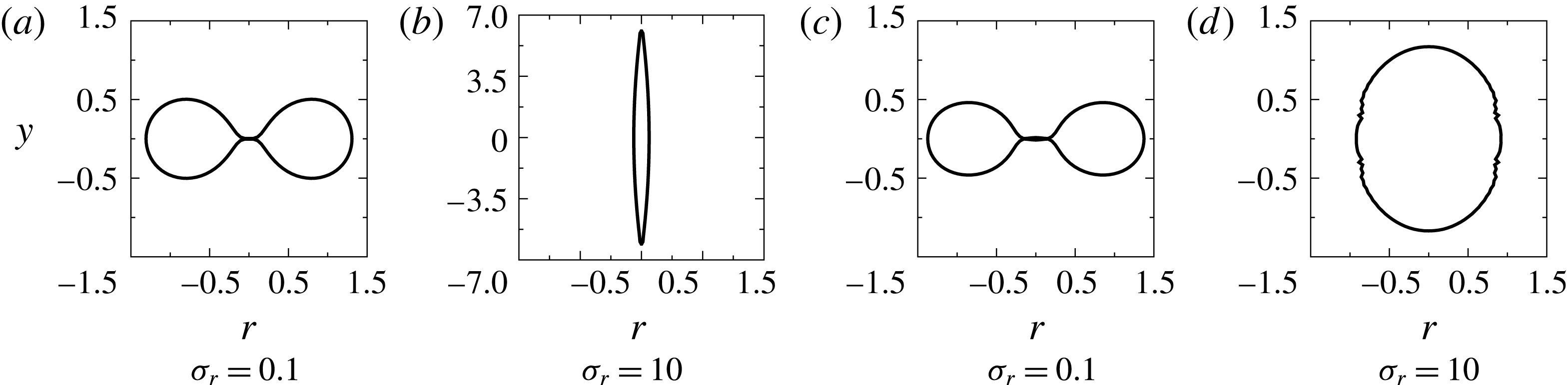
1 Introduction
An elastic capsule can be considered to be a drop of a liquid separated from another liquid by a very thin elastic membrane (Barthès-Biesel & Rallison Reference Barthès-Biesel and Rallison1981). The role of such an elastic interface is not only to prevent permeation of one fluid into another, thereby preventing mixing of contents, but also to maintain the integrity of the capsule. The membrane can enclose a complex functional fluid; for example, biological cells are capsules with membranes enclosing cell organelles embedded in a thick cytoplasm. These membranes are made up of amphiphilic molecules such as lipids which form bilayers, block copolymers which can form monolayers or cross-linked surface-active moieties (Kataoka, Harada & Nagasaki Reference Kataoka, Harada and Nagasaki2001; Karyappa, Deshmukh & Thaokar Reference Karyappa, Deshmukh and Thaokar2014b ). They are popular as encapsulating agents and are used as carriers for drugs, genes and other biotechnologically relevant materials (Kataoka et al. Reference Kataoka, Harada and Nagasaki2001).
Biologically important capsules, such as red blood cells or capsules used in technological applications, are subjected to large external forces, such as shear or electric forces, during their life span. These forces can cause significant deformation in the capsules, resulting in mechanical membrane stresses. From a mechanics point of view, the membrane of an elastic capsule can be considered as a two-dimensional interface, characterized by an elastic modulus, which undergoes in-plane deformation (strain) to generate in-plane elastic stresses (Barthès-Biesel & Rallison Reference Barthès-Biesel and Rallison1981), etc. These elastic stresses resist the applied forces such that a force balance and thereby a steady shape is attained. Different kinds of constitutive relationships relating in-plane finite-deformation, strain measures to in-plane stresses have been developed for a variety of membrane materials having technological or biological significance. Previously used elastic solid (Lighthill Reference Lighthill1968) and liquid droplet (Hyman & Skalak Reference Hyman and Skalak1972) models have now been replaced by thin viscoelastic membrane models with properties, such as elastic and viscous moduli of the membrane, taking account of the microscopic response corresponding to the microstructure of the capsule. Among several membrane constitutive laws, the Mooney–Rivlin law (Green & Adkins Reference Green and Adkins1970) for a strain-softening membrane and the Skalak law (Skalak et al. Reference Skalak, Tozeren, Zarda and Chien1973) for a strain-hardening membrane are popularly used especially in the computational analyses of elastic capsules (Chang & Olbricht Reference Chang and Olbricht1993; Gao et al. Reference Gao, Leporatti, Moya, Donath and Möhwald2001; Dubreuil, Elsner & Fery Reference Dubreuil, Elsner and Fery2003; Keller & Sottos Reference Keller and Sottos2006; Fery & Weinkamer Reference Fery and Weinkamer2007).
The deformation of elastic capsules subjected to weak forces (shear or electric) have been studied using asymptotic theories that assume an expansion parameter, which is typically the capillary number (a ratio of destabilizing force, typically shear or electric, to the stabilizing elastic force), and the deformation is assumed to be proportional to the capillary number (Barthès-Biesel Reference Barthès-Biesel1980, Reference Barthès-Biesel1991; Barthès-Biesel & Chhim Reference Barthès-Biesel and Chhim1981; Barthès-Biesel & Rallison Reference Barthès-Biesel and Rallison1981; Ha & Yang Reference Ha and Yang2000; Kessler, Finken & Seifert Reference Kessler, Finken and Seifert2009; Finken, Kessler & Seifert Reference Finken, Kessler and Seifert2011; Vlahovska et al. Reference Vlahovska, Young, Danker and Misbah2011; Thaokar Reference Thaokar2016). In most examples of practical relevance, though, the capillary number, and thereby the deformation, can be quite high. The nonlinear elastic response becomes relevant, and accurate description is possible only by a suitable numerical method.
In the last three decades, several computational studies addressing a variety of issues in large-deformation problems in elastic capsules have been reported. Zhou & Pozrikidis (Reference Zhou and Pozrikidis1995) studied the deformation of a capsule with an area incompressible membrane in simple shear flow using the boundary integral method. Such a membrane develops tension because of the imposed area incompressibility under applied shear flow. Later, several other investigations reported the study of the deformation of capsules and red blood cells in shear flow and looked at aspects such as deformation under small and moderate capillary numbers (proportional to the rate of shear) (Finken et al. Reference Finken, Kessler and Seifert2011), the effects of viscosity ratio on deformation as well as tumbling and tank treading (Rao, Zahalak & Sutera Reference Rao, Zahalak and Sutera1994; Pozrikidis Reference Pozrikidis1995, Reference Pozrikidis2001; Ramanujan & Pozrikidis Reference Ramanujan and Pozrikidis1998; Kessler, Finken & Seifert Reference Kessler, Finken and Seifert2008; Sui et al. Reference Sui, Low, Chew and Roy2008b ; Le Reference Le2010; Finken et al. Reference Finken, Kessler and Seifert2011; Vlahovska et al. Reference Vlahovska, Young, Danker and Misbah2011), the effects of the initial shape of the capsule as well as membrane constitutive laws on deformation and instability beyond a critical capillary number (Navot Reference Navot1998; Skotheim & Secomb Reference Skotheim and Secomb2007; Sui et al. Reference Sui, Chew, Roy and Low2007, Reference Sui, Chen, Chew, Roy and Low2010). The sensitivity of the capsule deformation to the membrane constitutive laws has also been investigated; for example, computational studies on the deformation of a capsule with strain-hardening and strain-softening membranes under linear shear flow (Barthès-Biesel Reference Barthès-Biesel1991; Lac et al. Reference Lac, Barthès-Biesel, Pelekasis and Tsamopoulos2004; Lac & Barthès-Biesel Reference Lac and Barthès-Biesel2005; Sui et al. Reference Sui, Chew, Roy and Low2008a ) indicate that membrane resistance in a strain-hardening capsule (obeying the Skalak law) may prevent its burst. Also, experimental, theoretical and numerical analyses have been reported on the deformation of an elastic capsule in extensional flow to determine the membrane constitutive law, as well as to estimate the elastic properties of the capsule (Chang & Olbricht Reference Chang and Olbricht1993; Diaz, Pelekasis & Barthès-Biesel Reference Diaz, Pelekasis and Barthès-Biesel2000; Pozrikidis Reference Pozrikidis2001; de Loubens et al. Reference de Loubens, Deschamps, Boedec and Leonetti2015).
In the large-deformation limit, the numerical analysis of elastic interfaces interacting with fluids leads to a coupled solid–fluid interaction problem, which is known to present formidable numerical challenges. For instance, elastic instabilities (Finken & Seifert Reference Finken and Seifert2006; Dodson & Dimitrakopoulos Reference Dodson and Dimitrakopoulos2009) are commonly encountered in their numerical solution, thereby severely limiting analysis of large-deformation problems. A membrane that offers resistance to bending can suppress these numerical elastic instabilities (Kwak & Pozrikidis Reference Kwak and Pozrikidis2001; Pozrikidis Reference Pozrikidis2001; Sui et al. Reference Sui, Chew, Roy and Low2007; Dupont et al. Reference Dupont, Salsac, Barthès-Biesel, Vidrascu and Tallec2015). Several computational studies on the dynamics of elastic capsules ignore the bending resistance (Pozrikidis Reference Pozrikidis1995; Zhou & Pozrikidis Reference Zhou and Pozrikidis1995; Lac et al. Reference Lac, Barthès-Biesel, Pelekasis and Tsamopoulos2004), primarily due to the numerical challenges posed by the higher-order derivatives of the position vector in the calculation of the bending force. Thus, although highly relevant, a good numerical model for addressing large-deformation problems remains a challenge.
The present work addresses the large deformation of capsules induced by strong uniform DC electric fields. The response of capsules to electric fields is important in biomedical applications, such as electroporation (Crowley Reference Crowley1973; Tieleman Reference Tieleman2004), electrofusion (Neumann, Sowers & Jordan Reference Neumann, Sowers and Jordan1989) and cell separation and manipulation (Pethig Reference Pethig1996; Kang et al. Reference Kang, Li, Kalams and Eid2008). Moreover, the response of spherical globules such as drops, vesicles and capsules to the electric field can be used to understand the interfacial properties as well as novel aspects of electrohydrodynamics (Thaokar & Deshmukh Reference Thaokar and Deshmukh2010; Yamamoto et al. Reference Yamamoto, Aranda-Espinoza, Dimova and Lipowsky2010; Deshmukh & Thaokar Reference Deshmukh and Thaokar2012, Reference Deshmukh and Thaokar2013; Karyappa, Deshmukh & Thaokar Reference Karyappa, Deshmukh and Thaokar2014a ; Karyappa et al. Reference Karyappa, Deshmukh and Thaokar2014b ; Das, Mayya & Thaokar Reference Das, Mayya and Thaokar2015; McConnell, Vlahovska & Miksis Reference McConnell, Vlahovska and Miksis2015b ; Ouriemi & Vlahovska Reference Ouriemi and Vlahovska2015; Thaokar Reference Thaokar2016). A uniform field also implies axisymmetry in most cases, thereby allowing easy-to-analyse experiments, elegant analytical theory and simplified numerical models, such as the boundary element method (BEM).
Relatively few studies have been reported on the deformation of elastic capsules under DC (Ha & Yang Reference Ha and Yang2000) and AC (Thaokar Reference Thaokar2016) electric fields, both restricted to small-deformation limit. Experiments, small-deformation theory and boundary integral calculations of a capsule, with a conducting membrane, enclosing a conducting fluid and suspended in a dielectric external fluid medium, showed that its deformation could be quite different from that of drops. Moreover, it can be used to estimate linear and nonlinear elastic properties of a capsule (Karyappa et al. Reference Karyappa, Deshmukh and Thaokar2014b ).
Experimental investigations on the deformation of a vesicle in a strong electric field (Riske & Dimova Reference Riske and Dimova2006; Dimova et al. Reference Dimova, Riske, Aranda, Bezlyepkina, Knorr and Lipowsky2007, Reference Dimova, Bezlyepkina, Jordo, Knorr, Riske, Staykova, Vlahovska, Yamamoto, Yang and Lipowsky2009; Yamamoto et al. Reference Yamamoto, Aranda-Espinoza, Dimova and Lipowsky2010) and shear flow (Farutin & Misbah Reference Farutin and Misbah2012) showed squaring of a vesicle with high values of tension at the corners. This was also reaffirmed and explained by a few two-dimensional (McConnell, Miksis & Vlahovska Reference McConnell, Miksis and Vlahovska2013, Reference McConnell, Miksis and Vlahovska2015a ; McConnell et al. Reference McConnell, Vlahovska and Miksis2015b ; Hu et al. Reference Hu, Lai, Seol and Young2016) and three-dimensional (Kolahdouz & Salac Reference Kolahdouz and Salac2015a ,Reference Kolahdouz and Salac b ; Veerapaneni Reference Veerapaneni2016) computational analyses. Vesicles and capsules are inherently different on at least a few counts: vesicles are area-preserving, which means that a spherical vesicle cannot undergo deformation. Thus a vesicle can deform only if it has an excess area, and it resists deformation via bending forces as well as the uniform and non-uniform tensions generated to conserve the area. Capsules, on the other hand, can resist deformation by elastic forces which arise as a deviation from a reference, unstressed shape, which can also be a sphere.
In this work we consider a capsule with a membrane that exhibits a Skalak or neo-Hookean (a special case of Mooney–Rivlin model) membrane constitutive law along with the capacitor model for the electric field to study the dynamics of capsule deformation under a strong DC electric field. We ask the following questions: What is the response of a capsule characterized by a capacitance and conductance to externally applied uniform DC fields? (We address this using analytical theory and boundary integral calculations.) What is the effect of these electrical properties of a membrane as well as the competition between the various time scales in the problem, such as membrane charging time, Maxwell–Wagner relaxation time, membrane deformation time and hydrodynamic relaxation time, on the deformation? Is there a possibility of squaring and other large-deformation modes in elastic capsules, akin to that reported in vesicles and the necessary conditions thereof? And what are the possible breakup modes and their dependence on the type of membrane models?
2 Problem description
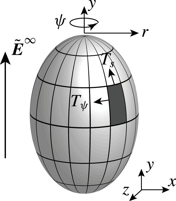
The schematic representation of a deformed elastic capsule in a uniform DC electric field is shown in figure 1. The electric field is applied parallel to the
 $y$
-axis, which is the axis of symmetry of the capsule. This field is defined by
 $\tilde{\boldsymbol{E}}^{\infty }=\tilde{E}_{0}\boldsymbol{e}_{y}$
, where
 $\tilde{E}_{0}$
is the strength of the electric field and thus acts in the positive
 $y$
-direction. In this article, all the notation with a tilde (
 $\tilde{~}$
) represents dimensional quantities, whereas that without a tilde represents their non-dimensional counterpart.
Schematic representation of a capsule in a uniform electric field.

The position vector, as measured from the origin, is given by
 $\tilde{\boldsymbol{x}}=\tilde{x}\boldsymbol{e}_{\boldsymbol{x}}+{\tilde{y}}\boldsymbol{e}_{\boldsymbol{y}}+\tilde{z}\boldsymbol{e}_{\boldsymbol{z}}$
, where
 $\boldsymbol{e}_{\boldsymbol{x}},~\boldsymbol{e}_{\boldsymbol{y}}$
and
 $\boldsymbol{e}_{\boldsymbol{z}}$
are the unit vectors in the
 $x$
-,
 $y$
- and
 $z$
-directions, respectively. The axis of symmetry of the capsule is assumed to coincide with the
 $y$
-axis, such that its centroid is at the origin. In the axisymmetric configuration (cylindrical coordinates),
 $y$
is the axis of the cylindrical coordinate system, whereas
 $\unicode[STIX]{x1D713}$
is the azimuthal angle. The radial coordinate
 $r=\sqrt{x^{2}+z^{2}}$
. A spherical coordinate system is used in the analytical theory (presented in appendix A), with
 $r=\sqrt{x^{2}+y^{2}+z^{2}}$
and azimuthal and polar angles
 $\unicode[STIX]{x1D713}$
and
 $\unicode[STIX]{x1D703}$
, respectively, where
 $\unicode[STIX]{x1D703}$
is measured from the
 $y$
-axis in the clockwise direction. Vectors
 $\boldsymbol{n}$
and
 $\boldsymbol{t}$
are the outward unit normal and clockwise unit tangent to the surface of the capsule, respectively. The dielectric constant and electrical conductivity of the internal fluid medium are
 $\unicode[STIX]{x1D716}_{i}$
and
 $\unicode[STIX]{x1D70E}_{i}$
, respectively, whereas the external medium has dielectric constant and electrical conductivity given by
 $\unicode[STIX]{x1D716}_{e}$
and
 $\unicode[STIX]{x1D70E}_{e}$
, respectively. Subscripts
 $i$
and
 $e$
stand for the internal and external fluid media of the capsule, respectively. The ratios of the electrical properties of the two media are defined as
 $\unicode[STIX]{x1D70E}_{r}=\unicode[STIX]{x1D70E}_{i}/\unicode[STIX]{x1D70E}_{e}$
and
 $\unicode[STIX]{x1D716}_{r}=\unicode[STIX]{x1D716}_{i}/\unicode[STIX]{x1D716}_{e}$
. Both the external and internal fluids are Newtonian, and the viscosities of the external and internal fluids are denoted by
 $\unicode[STIX]{x1D707}$
and
 $\unicode[STIX]{x1D706}\unicode[STIX]{x1D707}$
, respectively, where
 $\unicode[STIX]{x1D706}$
is the viscosity ratio. The mechanical properties of the membrane are elasticity
 $E_{s}$
and bending modulus
 $\unicode[STIX]{x1D705}_{b}$
. The electrical properties are capacitance
 $C_{m}=\unicode[STIX]{x1D716}_{m}\unicode[STIX]{x1D716}_{0}/d_{m}$
and conductance
 $G_{m}=\unicode[STIX]{x1D70E}_{m}/d_{m}$
, where
 $\unicode[STIX]{x1D716}_{m}$
,
 $\unicode[STIX]{x1D70E}_{m}$
and
 $d_{m}$
are membrane dielectric constant, conductivity and thickness, respectively, and
 $\unicode[STIX]{x1D716}_{0}$
is the permittivity of free space. The membrane is considered to be purely elastic, and viscous resistance is neglected. The time is scaled by the charge relaxation time of the outer fluid,
 $\tilde{t}_{e}=\unicode[STIX]{x1D716}_{e}\unicode[STIX]{x1D716}_{0}/\unicode[STIX]{x1D70E}_{e}$
, and the velocity is scaled by
 $E_{s}/\unicode[STIX]{x1D707}_{e}$
. The electric field
 $(\tilde{\boldsymbol{E}})$
, potential
 $(\tilde{\unicode[STIX]{x1D719}})$
and stress are scaled by
 $E_{0}$
,
 $E_{0}a$
and
 $E_{s}/a$
, where
 $a$
is the radius of the capsule and the scaling for the length. Other associated time scales in this problem are the hydrodynamic response time
 $\tilde{t}_{H}=\unicode[STIX]{x1D707}_{e}a/E_{s}$
, the Maxwell–Wagner charge relaxation time
 $\tilde{t}_{MW}=\unicode[STIX]{x1D716}_{0}(\unicode[STIX]{x1D716}_{i}+2\unicode[STIX]{x1D716}_{e})/(\unicode[STIX]{x1D70E}_{i}+2\unicode[STIX]{x1D70E}_{e})$
and the membrane charging time
 $\tilde{t}_{cap}=aC_{m}(1/\unicode[STIX]{x1D70E}_{i}+1/2\unicode[STIX]{x1D70E}_{e})$
(Grosse & Schwan Reference Grosse and Schwan1992; Dimova et al.
Reference Dimova, Bezlyepkina, Jordo, Knorr, Riske, Staykova, Vlahovska, Yamamoto, Yang and Lipowsky2009). The non-dimensional counterparts of all these time scales are
 $t_{e}=1$
,
 $t_{H}=\tilde{t}_{H}/\tilde{t}_{e}$
,
 $t_{MW}=\tilde{t}_{MW}/\tilde{t}_{e}=(2+\unicode[STIX]{x1D716}_{r})/(2+\unicode[STIX]{x1D70E}_{r})$
and
 $t_{cap}=\tilde{t}_{cap}/\tilde{t}_{e}={\hat{C}}_{m}(1/2+1/\unicode[STIX]{x1D70E}_{r})$
, where
 ${\hat{C}}_{m}=aC_{m}/\unicode[STIX]{x1D716}_{e}\unicode[STIX]{x1D716}_{0}$
is the non-dimensional membrane capacitance.
A balance between the Maxwell stresses caused by the electric field, the elastic forces and the hydrodynamic forces results in the evolution of a capsule into a new shape. It is of interest to establish a quantitative relationship between the deformation, elasticity and the strength of the electric field. In this analysis, the magnitude of the destabilizing electric force relative to the stabilizing elastic force is expressed in a single non-dimensional quantity, which is called the capillary number,
 $Ca=a\unicode[STIX]{x1D716}_{e}\unicode[STIX]{x1D716}_{0}E_{0}^{2}/E_{s}$
. Capsule deformation is analysed by considering neo-Hookean and Skalak types of membranes representing strain-softening and strain-hardening membranes, respectively. For modelling the electric response of the capsule to the applied electric field, a capacitive membrane model is used which incorporates the capacitance and conductance of the membrane, as well as the contrast in conductivity and dielectric constant of the internal and external fluid media. For simplicity of computations, the interface is considered to be impermeable, thereby preventing osmotic flows across the membrane. Since the elastic forces at large deformations are known to result in the formation of sharp edges and high curvatures, bending forces are included along with the elastic forces. Moreover, the inclusion of resistance to bending also allows removal of spurious elastic instabilities known to occur in elastic interfaces.
In this analysis, the Taylor deformation parameter is used as the measure of deformation (degree of deformation), given by
 $$\begin{eqnarray}DD=\frac{L-B}{L+B},\end{eqnarray}$$
where
 $L$
is the diameter of the capsule along the rotational axis of symmetry and
 $B$
is the equatorial diameter (Taylor Reference Taylor1934).
3 Problem formulation
The deformation of an elastic capsule in a uniform electric field is assumed to remain axisymmetric, with the axis parallel to the electric field lines. Therefore, to study the electrohydrodynamics of capsule deformation, the axisymmetric boundary integral method is considered. The electric, elastic and hydrodynamic forces, as well as the bending resistance of the membrane, are in equilibrium at the interface for an inertialess membrane, and these are discussed next.
3.1 Electrostatics
The electric potentials inside and outside of the capsule satisfy the Laplace equation
 $\unicode[STIX]{x1D6FB}^{2}\unicode[STIX]{x1D719}_{i,e}=0$
. Therefore the electric potential can be obtained as an integral equation by using Green’s theorem for the solution of the Laplace equation, to yield
 $$\begin{eqnarray}\displaystyle \frac{1}{2}\unicode[STIX]{x1D719}_{i}(\boldsymbol{x}_{0}) & = & \displaystyle \int _{s}[G^{E}(\boldsymbol{x},\boldsymbol{x}_{0})\unicode[STIX]{x1D735}\unicode[STIX]{x1D719}_{i}(\boldsymbol{x})\boldsymbol{\cdot }\boldsymbol{n}(\boldsymbol{x})-\unicode[STIX]{x1D719}_{i}(\boldsymbol{x})\boldsymbol{n}(\boldsymbol{x})\boldsymbol{\cdot }\unicode[STIX]{x1D735}G^{E}(\boldsymbol{x},\boldsymbol{x}_{0})]\,\text{d}s(\boldsymbol{x}),\end{eqnarray}$$
 $$\begin{eqnarray}\displaystyle \frac{1}{2}\unicode[STIX]{x1D719}_{e}(\boldsymbol{x}_{0}) & = & \displaystyle \unicode[STIX]{x1D719}^{\infty }(\boldsymbol{x}_{0})\nonumber\\ \displaystyle & & \displaystyle -\int _{s}[G^{E}(\boldsymbol{x},\boldsymbol{x}_{0})\unicode[STIX]{x1D735}\unicode[STIX]{x1D719}_{e}(\boldsymbol{x})\boldsymbol{\cdot }\boldsymbol{n}(\boldsymbol{x})-\unicode[STIX]{x1D719}_{e}(\boldsymbol{x})\boldsymbol{n}(\boldsymbol{x})\boldsymbol{\cdot }\unicode[STIX]{x1D735}G^{E}(\boldsymbol{x},\boldsymbol{x}_{0})]\,\text{d}s(\boldsymbol{x}),\end{eqnarray}$$
 $G^{E}(\boldsymbol{x},\boldsymbol{x}_{0})=1/(4\unicode[STIX]{x03C0}|\hat{\boldsymbol{x}}|)$
is the Green function for the Laplace equation,
 $\unicode[STIX]{x1D719}^{\infty }=-y$
is the applied potential (
 $\tilde{\unicode[STIX]{x1D719}}^{\infty }=-E_{o}{\tilde{y}}$
) and
 $\hat{\boldsymbol{x}}=\boldsymbol{x}-\boldsymbol{x}_{0}$
(McConnell et al.
Reference McConnell, Miksis and Vlahovska2013, Reference McConnell, Miksis and Vlahovska2015a
,Reference McConnell, Vlahovska and Miksis
b
).
The transmembrane potential, defined as the discontinuity in electrical potential across the interface, is given by
 $$\begin{eqnarray}\unicode[STIX]{x1D719}_{m}=\unicode[STIX]{x1D719}_{i}-\unicode[STIX]{x1D719}_{e},\end{eqnarray}$$
and it can be calculated from the electrical current continuity (a sum of displacement and ohmic currents) in the direction normal to the plane of the membrane (DeBruin & Krassowska Reference DeBruin and Krassowska1999),
 $$\begin{eqnarray}\unicode[STIX]{x1D70E}_{r}E_{n,i}+\unicode[STIX]{x1D716}_{r}\frac{\text{d}E_{n,i}}{\text{d}t}=E_{n,e}+\frac{\text{d}E_{n,e}}{\text{d}t}={\hat{C}}_{m}\frac{\text{d}\unicode[STIX]{x1D719}_{m}}{\text{d}t}+{\hat{G}}_{m}\unicode[STIX]{x1D719}_{m},\end{eqnarray}$$
where
 $E_{n,i}$
and
 $E_{n,e}$
are normal electric fields inside and outside of the membrane and
 ${\hat{G}}_{m}=aG_{m}/\unicode[STIX]{x1D70E}_{e}$
is the non-dimensional membrane conductance. Solving (3.1) along with (3.2) and (3.3), the tangential (derivative of potential with respect to the arclength) and normal electric fields can be calculated (termed the boundary integral method with capacitor model, BEM-CM).
The discontinuity of the electric traction across the interface is given by
 $\boldsymbol{f}^{E}=(\tilde{\unicode[STIX]{x1D749}}_{e}^{E}-\tilde{\unicode[STIX]{x1D749}}_{i}^{E})\boldsymbol{\cdot }\boldsymbol{n}=\tilde{\unicode[STIX]{x1D70F}}_{n}^{E}\boldsymbol{n}+\tilde{\unicode[STIX]{x1D70F}}_{t}^{E}\boldsymbol{t}$
, where the dimensional Maxwell electric stress
 $\tilde{\unicode[STIX]{x1D749}}^{E}=\unicode[STIX]{x1D716}\unicode[STIX]{x1D716}_{0}(\tilde{\boldsymbol{E}}\tilde{\boldsymbol{E}}-(\tilde{E}^{2}\unicode[STIX]{x1D644})/2)$
, considering
 $\unicode[STIX]{x1D644}$
as the identity tensor and
 $\unicode[STIX]{x1D716}$
as the dielectric constant of the fluid. The normal and tangential components of the electric stress tensor can be expressed in non-dimensional form as
 $$\begin{eqnarray}\displaystyle \unicode[STIX]{x1D70F}_{n}^{E} & = & \displaystyle {\textstyle \frac{1}{2}}Ca[(E_{n,e}^{2}-E_{t,e}^{2})-\unicode[STIX]{x1D716}_{r}(E_{n,i}^{2}-E_{t,i}^{2})],\end{eqnarray}$$
 $$\begin{eqnarray}\displaystyle \unicode[STIX]{x1D70F}_{t}^{E} & = & \displaystyle Ca(E_{n,e}E_{t,e}-\unicode[STIX]{x1D716}_{r}E_{n,i}E_{t,i}).\end{eqnarray}$$
3.2 Membrane laws and elastic stress
For an isotropic and area-dilating membrane, elastic tensions can be calculated using the Mooney–Rivlin model (Green & Adkins Reference Green and Adkins1970). According to the Mooney–Rivlin law, the membrane tension in the principal direction
 $i$
can be expressed as
 $$\begin{eqnarray}\tilde{T}_{i}^{MR}=\frac{\tilde{G}_{MR}}{\unicode[STIX]{x1D706}_{i}\unicode[STIX]{x1D706}_{j}}\left(\unicode[STIX]{x1D706}_{i}^{2}-\frac{1}{\unicode[STIX]{x1D706}_{i}^{2}\unicode[STIX]{x1D706}_{j}^{2}}\right)[\unicode[STIX]{x1D6FC}+\unicode[STIX]{x1D706}_{j}^{2}(1-\unicode[STIX]{x1D6FC})],\end{eqnarray}$$
where
 $G^{MR}$
and
 $\unicode[STIX]{x1D6FC}$
are the surface elastic modulus and a measure of the nonlinearity of the Mooney–Rivlin law, respectively, and
 $\unicode[STIX]{x1D706}_{i,j}$
are stretch ratios in principal directions
 $i$
and
 $j$
. The membrane nonlinearity parameter
 $\unicode[STIX]{x1D6FC}$
varies in the range of
 $[0,1]$
; the special case corresponding to
 $\unicode[STIX]{x1D6FC}=1$
is termed the neo-Hookean law, and it is used in this work (Barthès-Biesel, Diaz & Dhenin Reference Barthès-Biesel, Diaz and Dhenin2002).
The relation between the non-dimensional membrane elastic tensions and the stretch ratios for a strain-hardening membrane in the principal direction
 $i$
is given by Skalak et al. (Reference Skalak, Tozeren, Zarda and Chien1973) as
 $$\begin{eqnarray}\tilde{T}_{i}^{SK}=\frac{\tilde{G}^{SK}}{\unicode[STIX]{x1D706}_{i}\unicode[STIX]{x1D706}_{j}}[\unicode[STIX]{x1D706}_{i}^{2}(\unicode[STIX]{x1D706}_{i}^{2}-1)+C(\unicode[STIX]{x1D706}_{i}\unicode[STIX]{x1D706}_{j})^{2}\{(\unicode[STIX]{x1D706}_{i}\unicode[STIX]{x1D706}_{j})^{2}-1\}],\end{eqnarray}$$
where the first term on the right-hand side accounts for the shear deformation associated with the modulus
 $G^{SK}$
and the second term accounts for the area dilatation with modulus
 $CG^{SK}$
. The area dilatation parameter
 $C$
controls the extent of change in the area; the higher the value of
 $C$
, the lower is the membrane dilatation. In this work, a small value of
 $C=1$
is chosen to allow the membrane to change its area during deformation. Membrane tension in the principal direction
 $j$
can be expressed by interchanging indices in the corresponding constitutive relations (3.5) and (3.6). In our consideration,
 $i$
is the meridional and
 $j$
is the azimuthal principal directions, and the corresponding tensions are considered as
 $T_{s}$
and
 $T_{\unicode[STIX]{x1D713}}$
. In the small-deformation limit,
 $G^{MR}$
and
 $G^{SK}$
are related to the surface Young’s modulus
 $E_{s}$
(Barthès-Biesel et al.
Reference Barthès-Biesel, Diaz and Dhenin2002) as
 $E_{s}=3G^{MR}=2G^{SK}(1+2C)/(1+C)$
.
The combined contribution of the elastic tensions (force/length) obtained from the constitutive laws governs the membrane elastic traction (force/area), given by
 $\boldsymbol{f}^{el}=\unicode[STIX]{x1D70F}_{n}^{el}\boldsymbol{n}+\unicode[STIX]{x1D70F}_{t}^{el}\boldsymbol{t}$
, exerted at the interface. The elastic stress components can be obtained as
 $$\begin{eqnarray}\displaystyle \unicode[STIX]{x1D70F}_{n}^{el} & = & \displaystyle -(K_{s}T_{s}+K_{\unicode[STIX]{x1D713}}T_{\unicode[STIX]{x1D713}}),\end{eqnarray}$$
 $$\begin{eqnarray}\displaystyle \unicode[STIX]{x1D70F}_{t}^{el} & = & \displaystyle \frac{\text{d}T_{s}}{\text{d}s}+\frac{1}{r}\frac{\text{d}r}{\text{d}s}(T_{s}-T_{\unicode[STIX]{x1D713}}),\end{eqnarray}$$
 $K_{s}=|\text{d}\boldsymbol{t}/\text{d}s|$
and
 $K_{\unicode[STIX]{x1D713}}=n_{r}/r$
are principal curvatures of the meridional surface. Finally,
 $t_{y}=n_{r}=\text{d}y/\text{d}s$
and
 $t_{r}=-n_{y}=\text{d}r/\text{d}s$
are the
 $y$
and
 $r$
components of the unit normal and tangent vectors at the interface, respectively.
3.3 Resistance due to bending
Even though a thin elastic membrane has a very low resistance to bending deformation, it can have a significant contribution to the restoring forces, especially in regions of high curvature. The overall dimensionless bending force (force/area) is given by
 $$\begin{eqnarray}\boldsymbol{f}^{b}=\hat{\unicode[STIX]{x1D705}}_{b}[2\unicode[STIX]{x0394}_{s}H+4H(H^{2}-K_{G})]\boldsymbol{n},\end{eqnarray}$$
where
 $H=(K_{s}+K_{\unicode[STIX]{x1D713}})/2$
and
 $K_{G}=K_{s}K_{\unicode[STIX]{x1D713}}$
are the mean curvature and Gaussian curvature, respectively, the non-dimensional bending rigidity,
 $\hat{\unicode[STIX]{x1D705}}_{b}=\unicode[STIX]{x1D705}_{b}/a^{2}E_{s}$
, is the ratio of the bending force to the elastic force, and
 $\unicode[STIX]{x0394}_{s}H$
is the Laplace–Beltrami operator of the mean curvature in the cylindrical coordinate system, defined as
 $$\begin{eqnarray}\unicode[STIX]{x0394}_{s}H=\unicode[STIX]{x1D735}_{s}\boldsymbol{\cdot }(\unicode[STIX]{x1D735}_{s}H)=\frac{1}{r|\boldsymbol{X}_{s}|}\frac{\unicode[STIX]{x2202}}{\unicode[STIX]{x2202}s}\left(\frac{r}{|\boldsymbol{X}_{s}|}\frac{\unicode[STIX]{x2202}H}{\unicode[STIX]{x2202}s}\right),\end{eqnarray}$$
where
 $|\boldsymbol{X}_{s}|=\sqrt{(\unicode[STIX]{x2202}r/\unicode[STIX]{x2202}s)^{2}+(\unicode[STIX]{x2202}y/\unicode[STIX]{x2202}s)^{2}}$
(Hu, Kim & Lai Reference Hu, Kim and Lai2014). Higher-order derivatives of mean curvature with respect to arclength are calculated using the spectral method for better accuracy in estimating bending force (Trefethen Reference Trefethen1996).
3.4 Hydrodynamics
Typically, capsule sizes range from
 $0.1~\unicode[STIX]{x03BC}\text{m}$
to a few hundred micrometres, which means that the flow inside and outside the capsule can be considered to obey low-Reynolds-number hydrodynamics and therefore the Stokes equations suffice to describe the problem. Thus
 $$\begin{eqnarray}\unicode[STIX]{x1D735}\boldsymbol{\cdot }\boldsymbol{u}=0,\quad \unicode[STIX]{x1D735}\boldsymbol{\cdot }\unicode[STIX]{x1D749}^{H}=0,\end{eqnarray}$$
where the viscous stress for the internal fluid domain
 $V_{i}$
and external fluid domain
 $V_{e}$
are given by
 $$\begin{eqnarray}\displaystyle \unicode[STIX]{x1D749}^{H} & = & \displaystyle -P\unicode[STIX]{x1D644}+\unicode[STIX]{x1D706}(\unicode[STIX]{x1D735}\boldsymbol{u}+\unicode[STIX]{x1D735}\boldsymbol{u}^{\text{T}})\quad \text{at }V_{i},\end{eqnarray}$$
 $$\begin{eqnarray}\displaystyle \unicode[STIX]{x1D749}^{H} & = & \displaystyle -P\unicode[STIX]{x1D644}+(\unicode[STIX]{x1D735}\boldsymbol{u}+\unicode[STIX]{x1D735}\boldsymbol{u}^{\text{T}})\quad \text{at }V_{e},\end{eqnarray}$$
 $\unicode[STIX]{x1D749}^{H}$
is the hydrodynamic stress tensor, and
 $\boldsymbol{u}$
and
 $P$
are the velocity and pressure fields, respectively.
The solution to (3.10) results in the interfacial velocity being described in an integral form as
 $$\begin{eqnarray}\boldsymbol{u}(\boldsymbol{x}_{0})=-\frac{1}{1+\unicode[STIX]{x1D706}}\frac{1}{4\unicode[STIX]{x03C0}}\int _{s}\unicode[STIX]{x0394}\boldsymbol{f}(\boldsymbol{x})\boldsymbol{\cdot }\boldsymbol{G}(\boldsymbol{x},\boldsymbol{x}_{0})\,\text{d}s(\boldsymbol{x})+\frac{1}{4\unicode[STIX]{x03C0}}\frac{1-\unicode[STIX]{x1D706}}{1+\unicode[STIX]{x1D706}}\int _{s}\boldsymbol{u}(\boldsymbol{x})\boldsymbol{\cdot }\boldsymbol{Q}(\boldsymbol{x},\boldsymbol{x}_{0})\boldsymbol{\cdot }\boldsymbol{n}(\boldsymbol{x})\,\text{d}s(\boldsymbol{x}),\end{eqnarray}$$
where
 $\boldsymbol{G}(\boldsymbol{x},\boldsymbol{x}_{0})$
and
 $\boldsymbol{Q}(\boldsymbol{x},\boldsymbol{x}_{0})$
are Green’s functions for velocity (stokeslet) and stress (stresslet), respectively, and
 $\unicode[STIX]{x0394}\boldsymbol{f}$
is the unbalanced non-hydrodynamic traction acting on the interface (Rallison & Acrivos Reference Rallison and Acrivos1978). For an unbounded three-dimensional flow, the stokeslet and the stresslet are defined as
 $$\begin{eqnarray}\boldsymbol{G}(\boldsymbol{x},\boldsymbol{x}_{0})=\frac{\unicode[STIX]{x1D644}}{|\hat{\boldsymbol{x}}|}+\frac{\hat{\boldsymbol{x}}\hat{\boldsymbol{x}}}{|\hat{\boldsymbol{x}}|^{3}},\quad \boldsymbol{Q}(\boldsymbol{x},\boldsymbol{x}_{0})=-6\frac{\hat{\boldsymbol{x}}\hat{\boldsymbol{x}}\hat{\boldsymbol{x}}}{|\hat{\boldsymbol{x}}|^{5}}\quad \text{where }\hat{\boldsymbol{x}}=\boldsymbol{x}-\boldsymbol{x}_{0},\end{eqnarray}$$
where
 $\boldsymbol{x}_{0}$
and
 $\boldsymbol{x}$
are the source point and the observation point, respectively. The viscosities of both fluids are assumed to be the same, i.e.
 $\unicode[STIX]{x1D706}=1$
, whereby the double-layer potential, the second term on the right-hand side of (3.12), drops out. The boundary integral equation (3.12) is solved to obtain the interfacial velocity of a capsule in an applied uniform electric field (Pozrikidis Reference Pozrikidis1990; Deshmukh & Thaokar Reference Deshmukh and Thaokar2012, Reference Deshmukh and Thaokar2013; Karyappa et al.
Reference Karyappa, Deshmukh and Thaokar2014b
). The non-hydrodynamic tractions responsible for the deformation of the capsule, in this case, include the elastic traction, electric traction and traction due to the resistance to bending. The net non-hydrodynamic traction acting at the interface is given by
 $$\begin{eqnarray}\unicode[STIX]{x0394}\boldsymbol{f}=-(\,\boldsymbol{f}^{el}+\boldsymbol{f}^{b}+\boldsymbol{f}^{E}).\end{eqnarray}$$
Eventually, the deformed shape of the capsule,
 $\boldsymbol{x}(t)$
, can be calculated from the kinematic condition given by
 $$\begin{eqnarray}\boldsymbol{x}(t)=\boldsymbol{x}(t-1)+\frac{1}{t_{H}}\boldsymbol{u}\unicode[STIX]{x0394}t,\end{eqnarray}$$
where
 $\boldsymbol{x}(t-1)$
is the shape of the capsule at the previous time,
 $(t-1)$
, and
 $\unicode[STIX]{x0394}t$
is the time step used in boundary integral calculation.
4 Results
Results are presented for the analysis of the dynamics of axisymmetric deformation of an elastic capsule, placed in a uniform DC electric field. The membrane conductance
 ${\hat{G}}_{m}=0$
, capacitance
 ${\hat{C}}_{m}=50$
, ratio of dielectric constant
 $\unicode[STIX]{x1D716}_{r}=1$
and hydrodynamic response time
 $t_{H}=1$
, unless explicitly mentioned. Assuming a very small contribution of the resistance due to bending, a small value of dimensionless rigidity modulus
 $\hat{\unicode[STIX]{x1D705}}_{b}=0.001$
is considered, and the criticality of incorporating bending is clearly demonstrated in the supplementary material (§ B.1) available at https://doi.org/10.1017/jfm.2018.89. The axisymmetric boundary integral method is used to simulate the Stokes equations in which the azimuthal elliptic integrals are solved using analytical theory and integrations in the meridional plane are carried out numerically using 16-point Gaussian quadrature considering 60 collocation points over the arclength between poles (north–south).
A detailed convergence test on the change in volume
 $(\unicode[STIX]{x0394}v)$
, degree of deformation
 $(DD)$
and transmembrane potential
 $(\unicode[STIX]{x1D719}_{m})$
over the half arclength as a function of number of elements has been carried out, and the details are provided in the supplementary material (§ B.2). The analysis suggests that the selection of
 $60$
elements over the half arclength (north pole–south pole) as well as
 $\unicode[STIX]{x0394}t=0.01$
yield satisfactory results.
4.1 Validation of the numerical code
For validating the electrostatics in the BEM code, a simplified electrostatic model (SEM) is suggested (§ A.1.1) by assuming that the Maxwell–Wagner charge relaxation time is much smaller than the capacitor charging time, i.e.
 $t_{MW}<t_{cap}$
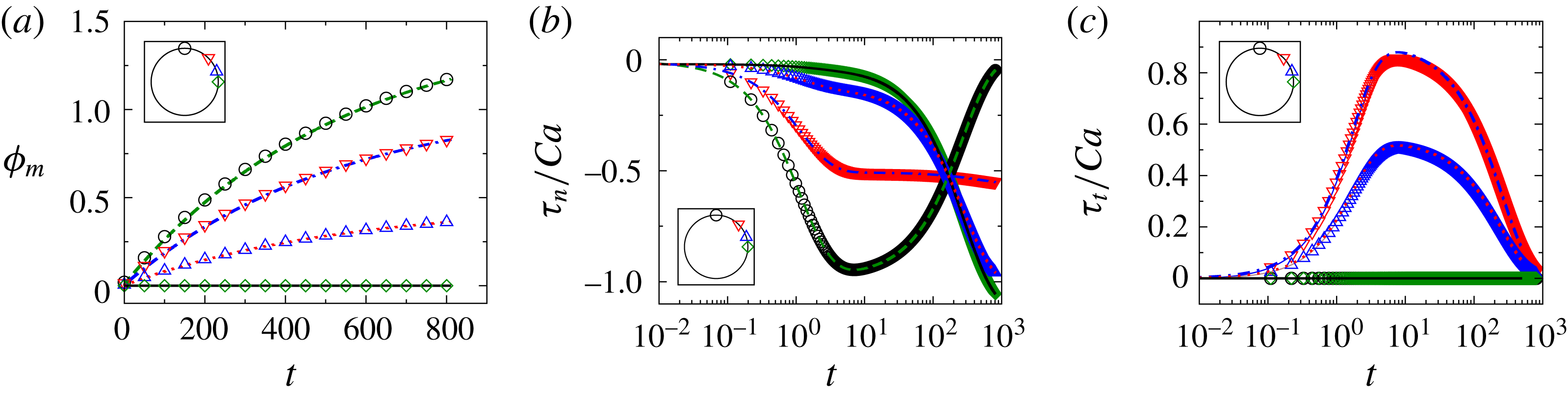
. In this limit, the analytical solution for the deformation of a capsule is obtained and compared with numerical computations (figure 22
a–c in § A.2.2). The variation of transmembrane potential obeys
 $\unicode[STIX]{x1D719}_{m}=(3/2)(1-\text{e}^{-t/t_{cap}})\cos \unicode[STIX]{x1D703}$
, which suggests that the charging time is proportional to capacitance and equal to
 $3{\hat{C}}_{m}/2$
for
 $\unicode[STIX]{x1D70E}_{r}=1$
(Grosse & Schwan Reference Grosse and Schwan1992; Schwalbe, Vlahovska & Miksis Reference Schwalbe, Vlahovska and Miksis2011). The membrane becomes fully charged at long times with equal and opposite non-dimensional charge densities on both sides of the membrane (equal to
 $3{\hat{C}}_{m}/2$
) such that the net charge is zero.
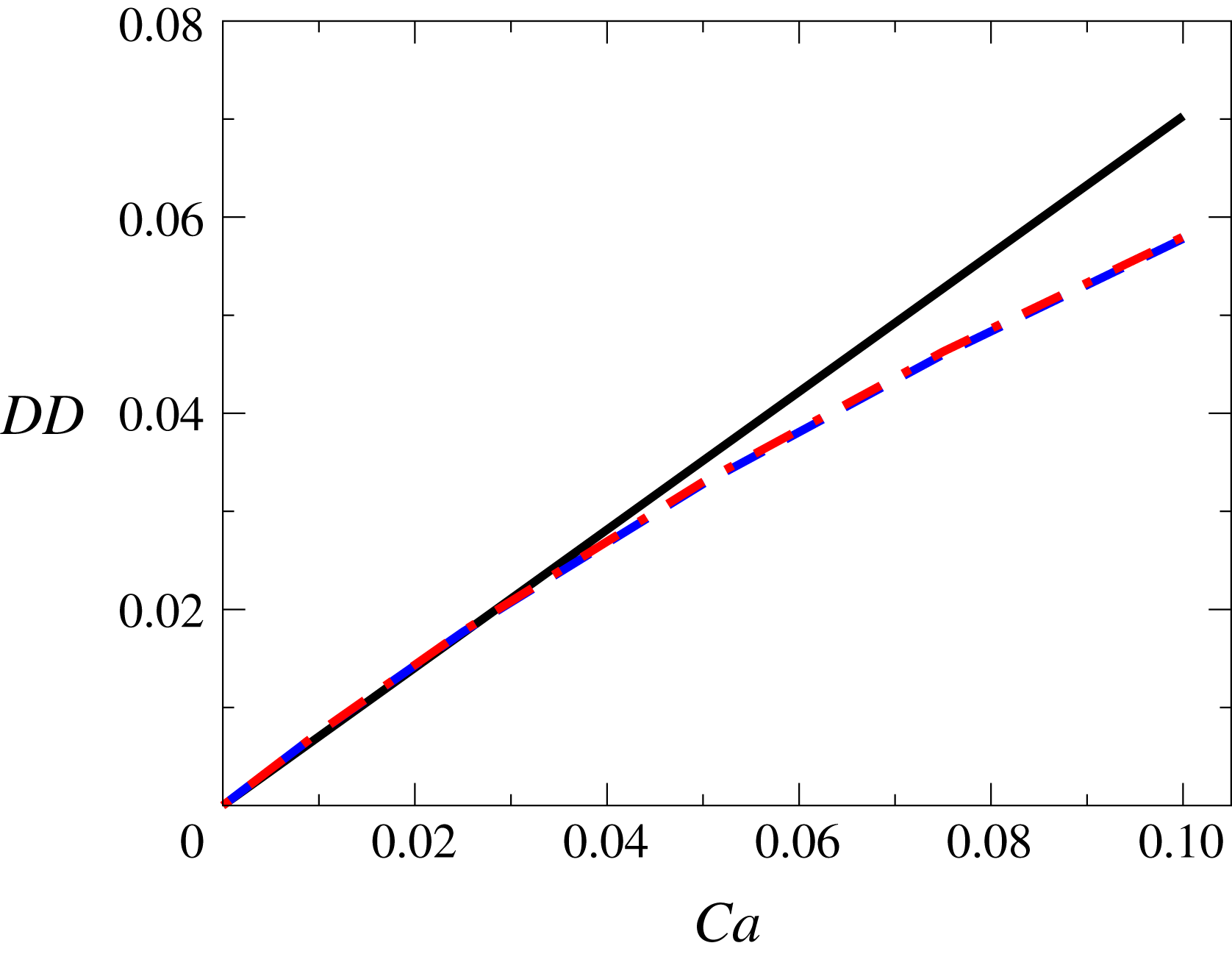
The deformation of an elastic capsule in an electric field can be analytically solved in the small-capillary-number limit. The steady-state deformation of a capsule obtained from the boundary integral method for a neo-Hookean membrane and a Skalak membrane are compared (figure 2) with the results obtained from simplified electrostatic theory (SEM) (§ A.1.1) considering
 ${\hat{C}}_{m}=50$
,
 ${\hat{G}}_{m}=0$
,
 $\unicode[STIX]{x1D716}_{r}=1$
and
 $\unicode[STIX]{x1D70E}_{r}=1$
(although it does not depend upon
 $\unicode[STIX]{x1D70E}_{r}$
, which is discussed in § 4.2.3). It can be observed that the deformations considering neo-Hookean and Skalak membrane laws are in good agreement with the analytical theory in the small-deformation limit and both kinds of membranes exhibit the same degree of deformation, which in turn is identical to that given by a Hookean membrane. A deviation is observed at higher capillary numbers because of corrections to both electrostatics, as well as elastic deformation.
Comparison of degree of deformation as a function of
 $Ca$
obtained from analytical theory (——), the boundary integral simulation considering the SEM with Skalak law (— ⋅ —) and the neo-Hookean law (– – –) considering
 ${\hat{C}}_{m}=50$
,
 ${\hat{G}}_{m}=0$
,
 $\unicode[STIX]{x1D716}_{r}=1$
and
 $\unicode[STIX]{x1D70E}_{r}=1$
.

The numerical boundary integral method to solve the electrostatics is further validated with the analytical electrostatics theory (AET), discussed in § A.2.1. AET solves electrostatics equations over an undeformed sphere (figure 23
a–c for
 $\unicode[STIX]{x1D70E}_{r}=1$
; figure 24
a–c for
 $\unicode[STIX]{x1D70E}_{r}=10$
; and figure 25
a–c for
 $\unicode[STIX]{x1D70E}_{r}=0.1$
in § A.2.2). Analytical theory for deformation, though, is not provided in this limit. It should be mentioned here that, in the analytical theory as well as in the numerical model, the choice of initial condition on the inner and outer electric field is critical, and is a characteristic of the capacitor model. In this work, we assume that the non-dimensional inner and outer normal electric field at
 $t=0$
is given by
 $\cos \unicode[STIX]{x1D703}$
. This presupposes that the capacitor is uncharged at
 $t=0$
, and offers no impedance; thereby the two fluids, which have the same dielectric constants (as assumed in this work), have the same initial electric fields.
4.2 Dynamics of capsule deformation at small and intermediate capillary numbers
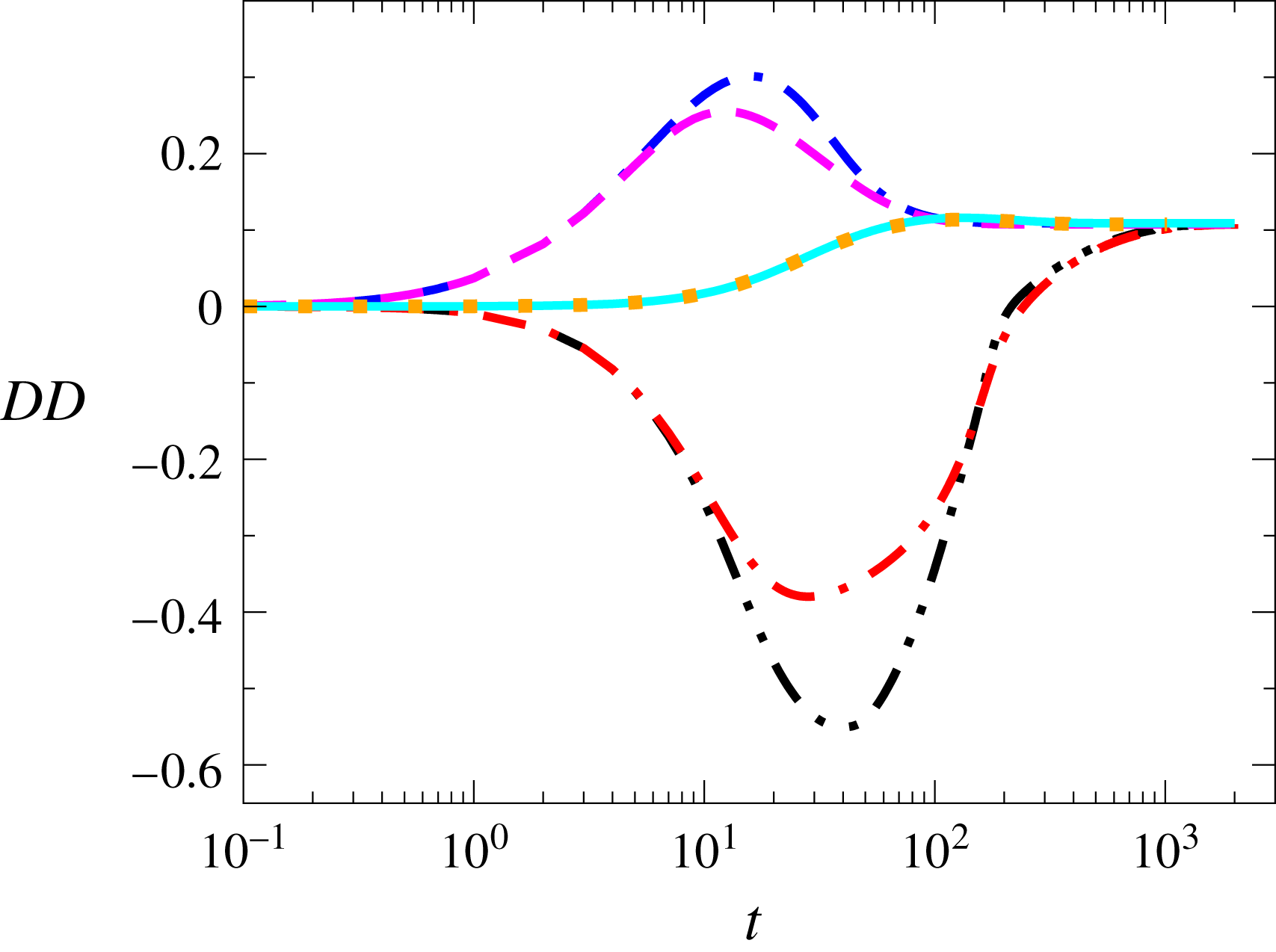
The dynamics of deformation of spherical capsules with a Skalak or a neo-Hookean membrane at
 $\unicode[STIX]{x1D70E}_{r}=10,~1$
and
 $0.1$
is shown in figure 3. These results are obtained using boundary integral calculations with
 $\unicode[STIX]{x1D716}_{r}=1$
,
 ${\hat{C}}_{m}=50$
and
 ${\hat{G}}_{m}=0$
at a small capillary number,
 $Ca=0.25$
. The different time scales considered in this work are summarized in table 1. The distinctive behaviour of the dynamics at different conductivity ratios and for two different membrane types are explained in the following subsections.
Associated time scales at different conductivity ratios.

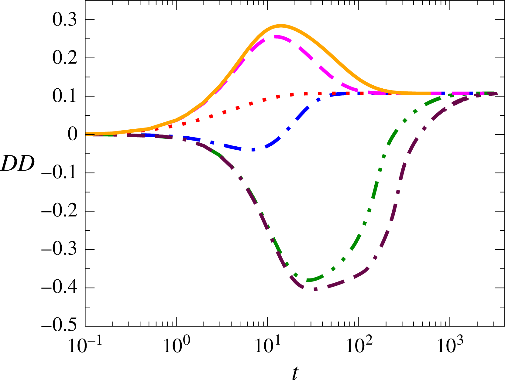
Dynamics for the deformation of a capsule with Skalak membrane at
 $\unicode[STIX]{x1D70E}_{r}=10$
(– – –), 1 (⋯⋯) and 0.1 (— ⋅ —), and for the deformation of a capsule with neo-Hookean membrane at
 $\unicode[STIX]{x1D70E}_{r}=10$
(– – ⋅ – –), 1 (——) and 0.1 (— ⋅ ⋅ —) at
 $Ca=0.25$
.

4.2.1 Case of
 $\unicode[STIX]{x1D70E}_{r}=1$

For
 $\unicode[STIX]{x1D70E}_{r}=1$
, the deformation of a spherical capsule with either a Skalak or a neo-Hookean membrane attains an intermediate maximum prolate deformation at
 $t=132$
and slowly reaches a steady-state deformation at
 $Ca=0.25$
considering
 $\unicode[STIX]{x1D716}_{r}=1$
,
 ${\hat{C}}_{m}=50$
and
 ${\hat{G}}_{m}=0$
(figure 3). Both Skalak and neo-Hookean capsules show nearly identical dynamics of deformation. Although there is no dielectric constant or conductivity contrast between the internal and external fluids, a steady-state prolate deformation is observed. The normal electric fields are identical in the two fluids at all times; the tangential field though is discontinuous, such that the external fluid has a higher magnitude than the inner fluid owing to the transmembrane potential. At
 $t=0$
, the normal (outward) and tangential fields (anticlockwise) are equal for both internal and external fluids on account of the same conductivities and dielectric constants, and hence no net Maxwell stress is generated, and deformation is absent. As time progresses, the normal electric field falls to zero, over the membrane charging time, and at still longer times a fully charged non-conducting membrane leads to zero current. The tangential field, on the other hand, continues to be negative (anticlockwise), with the inner field always lower than the outer, and the difference between the two is proportional to the transmembrane potential. At long times, the inner tangential field is zero, and the outer is
 $-(3/2)\sin \unicode[STIX]{x1D703}$
, corresponding to the transmembrane potential (figure 23
a in § A.2.2). Thus, the normal Maxwell stresses arise purely due to the tangential field (normal stress is proportional to
 $E_{n}^{2}-E_{t}^{2}$
, and
 $E_{n}$
is the same in the inner and outer surfaces). Therefore the normal stresses are always compressive, since the tangential electric field on the outer surface is always higher (figure 23
b in § A.2.2). The net normal compressive stress can be written as an isotropic compressive part and a tensile part corresponding to the second Legendre polynomial of
 $\cos \unicode[STIX]{x1D703}$
. This tensile part leads to prolate deformation. The tangential stresses are zero at
 $t=0$
and
 $t=\infty$
, because of the absence of electric contrast and normal electric fields being zero, respectively. The tangential stresses are from the equator to the pole at intermediate times (figure 23
c in § A.2.2).
4.2.2 Case of
$\unicode[STIX]{x1D70E}_{r}>1$

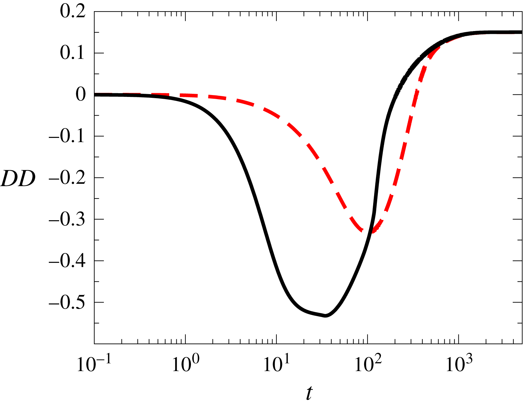
Figure 3 shows that for
 $\unicode[STIX]{x1D70E}_{r}=10$
the capsule initially undergoes a high prolate deformation and then it slowly relaxes back to a steady-state prolate shape. At very short times
 $t<t_{MW}$
, the two fluids act as dielectrics, and since there is no dielectric contrast, the deformation is zero. The two fluids act as leaky dielectrics at time
 $t\sim O(t_{MW})$
, and their conductivity ratio determines their deformation and increases as
 $\unicode[STIX]{x1D70E}_{r}$
increases. The membrane impedance is small since
 $t_{MW}<t_{cap}$
, and the membrane is not charged. Therefore, the electric field distribution, as well as the Maxwell stresses are similar to that observed in a liquid drop suspended in an ambient fluid and subjected to an electric field. The current continuity condition means that, when the inner fluid is more conducting (
 $\unicode[STIX]{x1D70E}_{r}=10$
), the polarization vector inside the drop is aligned in the direction of the electric field, whereby there are net positive charges at the north pole and net negative charges at the south pole. Thus, unlike the
 $\unicode[STIX]{x1D70E}_{r}=1$
case, even the normal field contributes to normal stresses and the normal stresses are predominantly tensile (figure 24
b in § A.2.2), hence a strong prolate deformation is observed. At
 $t>t_{cap}$
, the normal electric stress at the poles and the tangential stress over the interface disappear as the membrane becomes fully charged. Therefore, the prolate steady-state deformation is mainly due to the compressive electric stress, which is maximum at the equator (figure 24
b in § A.2.2). Note that prolate deformation is observed even in the absence of conductivity contrast, as discussed earlier for
 $\unicode[STIX]{x1D70E}_{r}=1$
and later elaborated for the case of
 $\unicode[STIX]{x1D70E}_{r}<1$
.
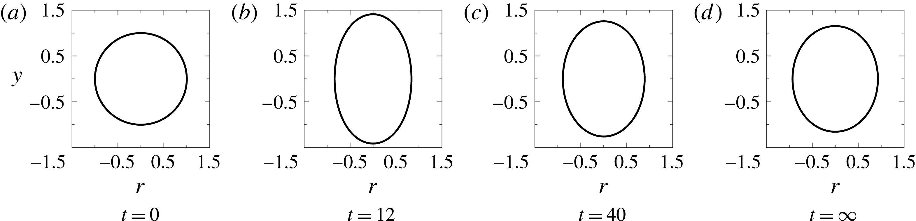
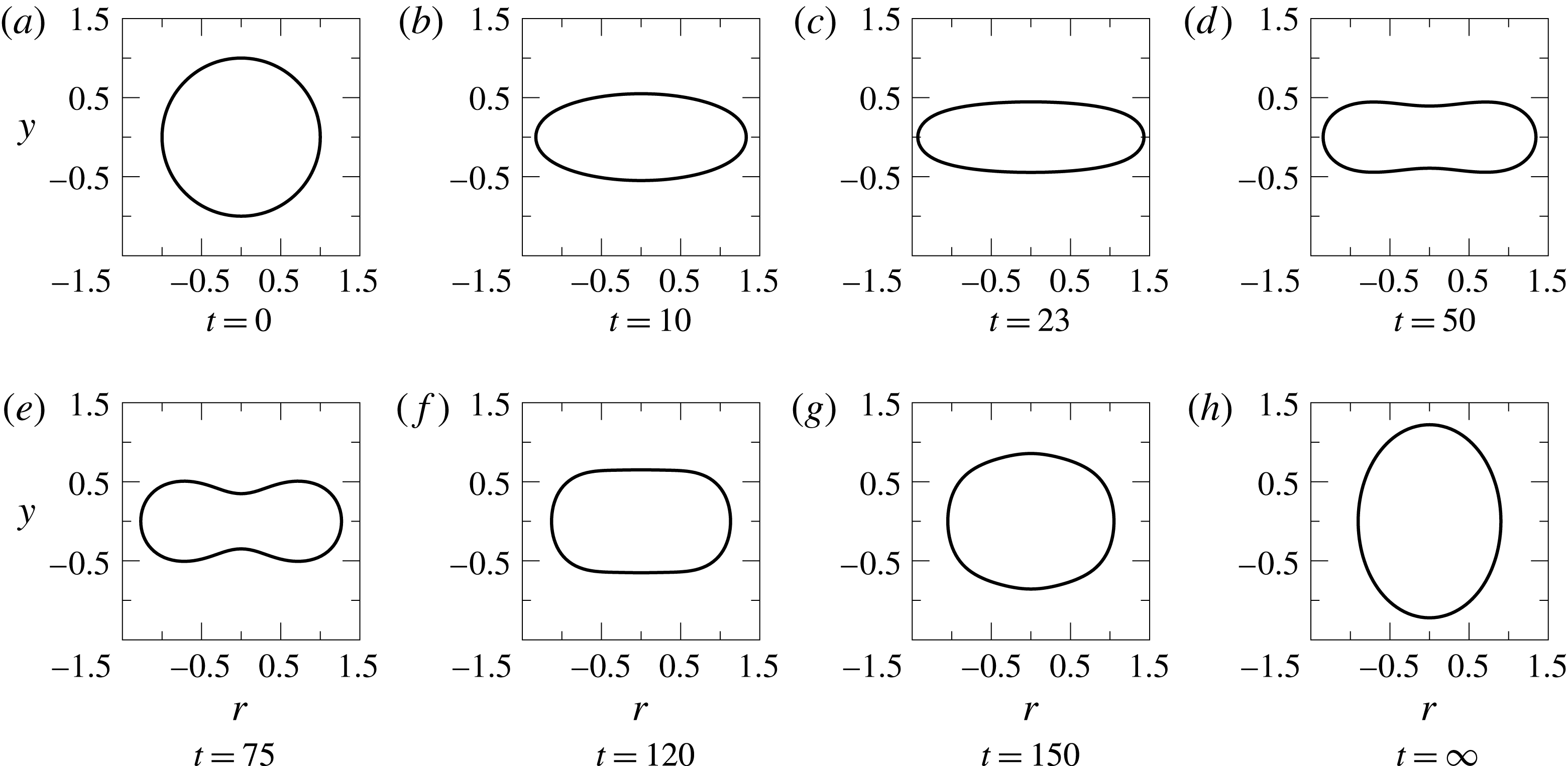
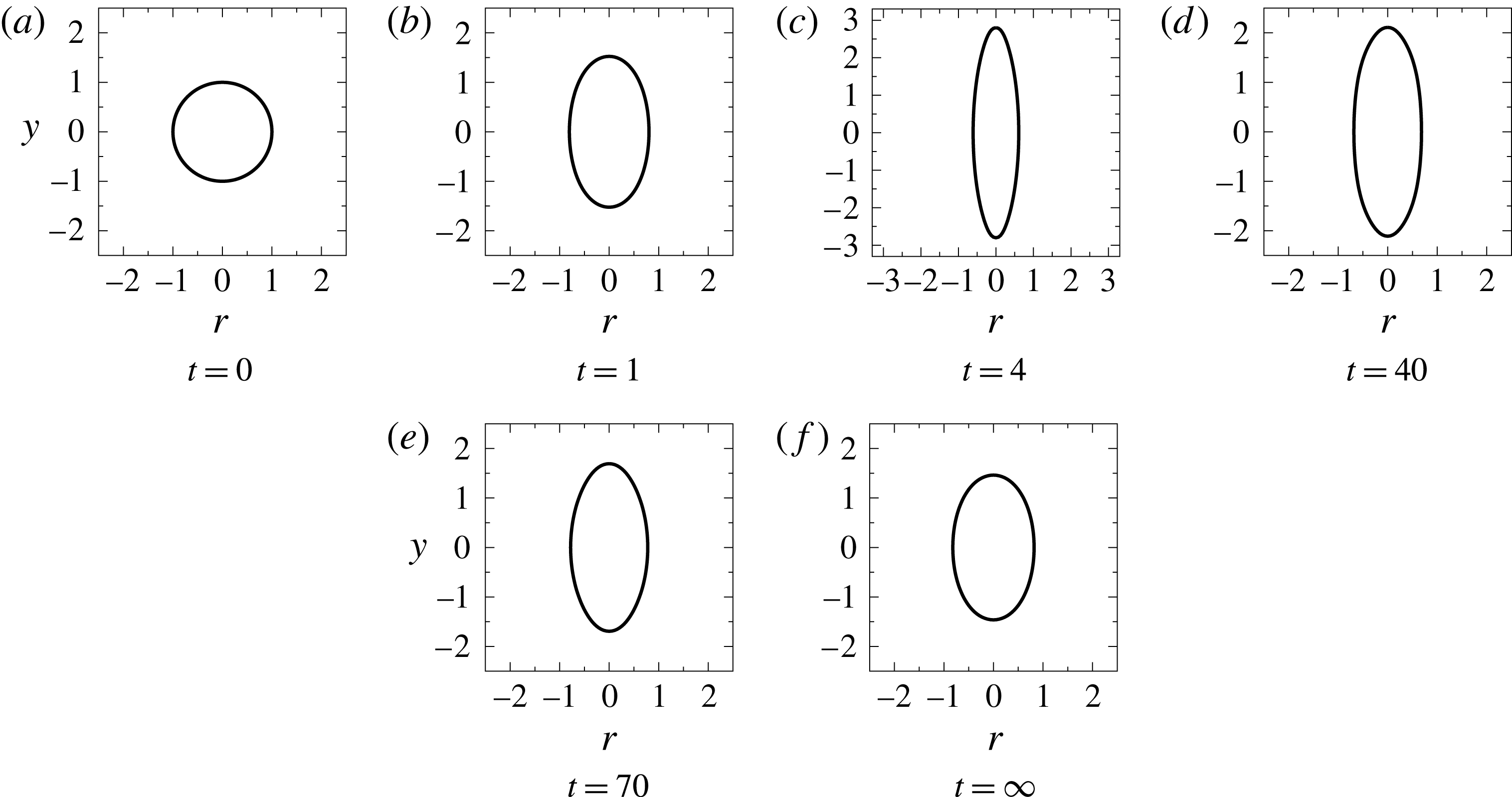
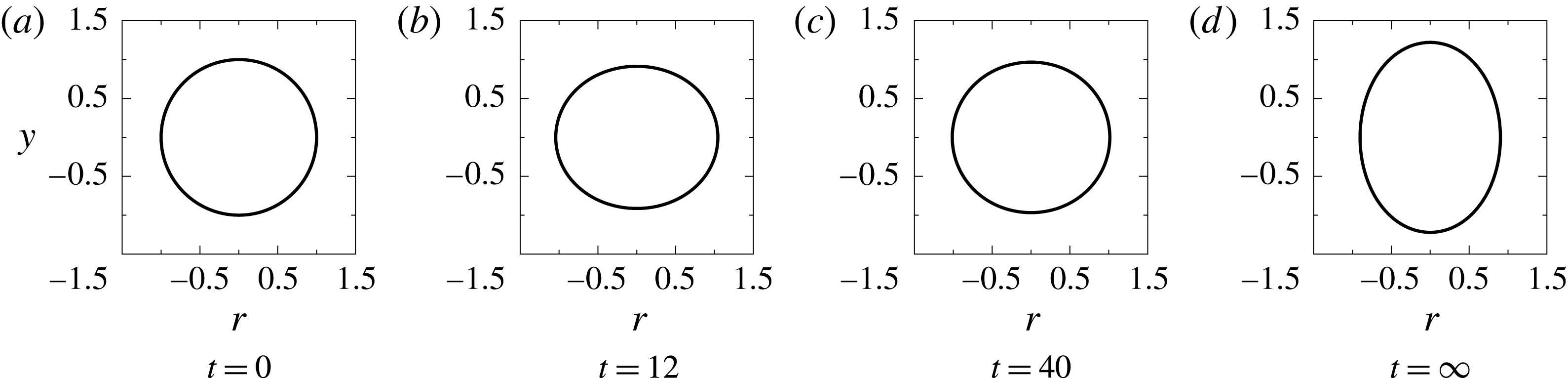
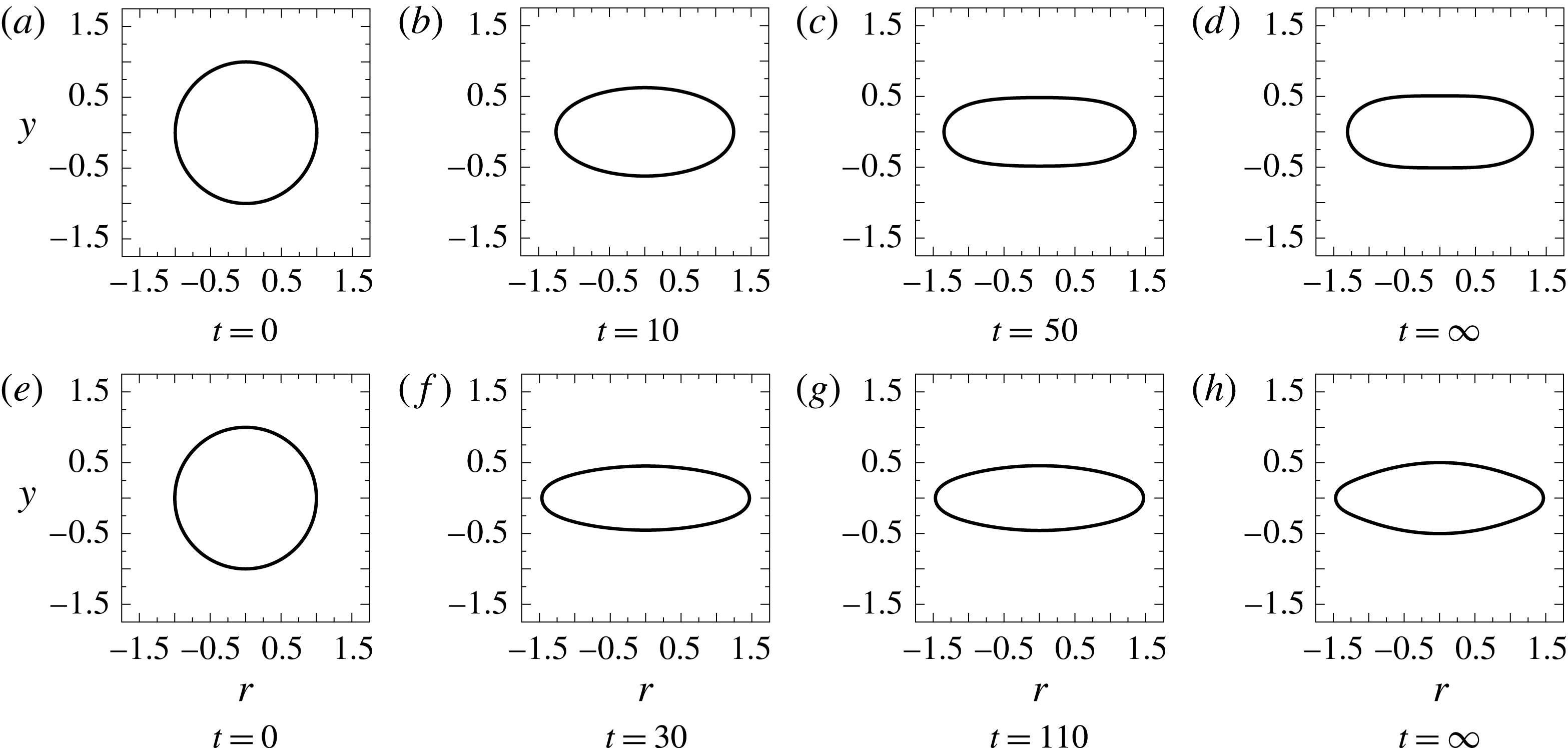
Shape evolution of a capsule with Skalak membrane at
 $\unicode[STIX]{x1D70E}_{r}=10$
for
 $Ca=0.25$
.

Intermediate shapes in the dynamics of the deformation of an elastic capsule from an initial spherical shape to the final steady-state shape at
 $Ca=0.25$
are shown in figure 4 for
 $\unicode[STIX]{x1D70E}_{r}=10$
. A spherical capsule undergoes an intermediate maximum prolate deformation (figure 4
b) before reaching the steady-state deformation (figure 4
d).
4.2.3 Case of
$\unicode[STIX]{x1D70E}_{r}<1$

When the external fluid is more conducting (
 $\unicode[STIX]{x1D70E}_{r}=0.1$
), at short times, the polarization vector is from north pole to south pole, opposite in direction to the applied field, that is, the north pole has a net negative charge, and the south pole has a net positive charge. Thus for
 $t\sim O(t_{MW})$
, the net Maxwell stress at the membrane interface is compressive and leads to an oblate shape. Note that the normal electric field leads to compressive normal stress, and the isotropic electric pressure is also compressive (see figure 25
a–c in § A.2.2 for variation of transmembrane potential, normal and tangential electric stresses with time on a static sphere).
Interestingly, irrespective of the conductivity ratio, the final steady-state deformations are the same and are prolate (figure 3). This independence of the final steady-state shape and deformation with respect to
 $\unicode[STIX]{x1D70E}_{r}$
can be easily understood: At long times the non-conducting membrane acts like a dielectric, thereby rendering the outer normal electric field zero as well as the corresponding tangential stress also zero (figures 23
c, 24
c and 25
c in § A.2.2). The Maxwell stress is, therefore, only normal (figures 23
b, 24
b and 25
b in § A.2.2). Moreover, since the normal electric field is zero, the normal electric stress is compressive (figures 23
b, 24
b and 25
b in § A.2.2) and is maximum at the equator, the deformation is always prolate.
Thus an oblate–prolate transition is observed at long times for
 $\unicode[STIX]{x1D70E}_{r}<1$
. A closed-form expression for the transition time is difficult to obtain on account of the equation resulting from
 $DD=0$
being implicit in time. The physics seems to be governed by the normal Maxwell stress going to zero, which in the case of SEM leads to
 $$\begin{eqnarray}t\propto t_{cap}\log \frac{\unicode[STIX]{x1D70E}_{r}+2\sqrt{2-\unicode[STIX]{x1D70E}_{r}^{2}}}{(2+\unicode[STIX]{x1D70E}_{r})}.\end{eqnarray}$$
This leads to a value of around
 $t=173$
for
 $\unicode[STIX]{x1D70E}_{r}=0.1$
 $(t_{cap}=525)$
, which is of the same order as
 $t=243$
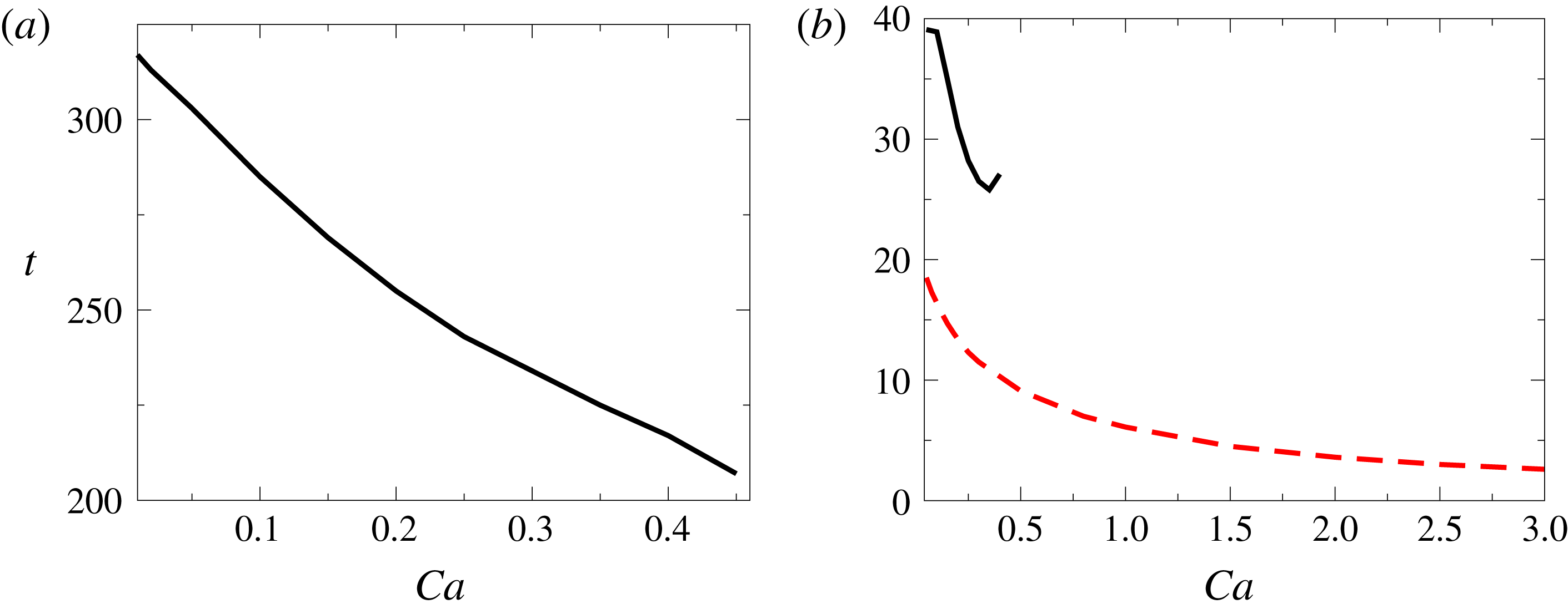
seen in figures 3 and 5(a). Thus the transition time can be expected to be of this order, although not exactly, since it also depends on the capillary number as well as on the ratio of hydrodynamic and electric time scales.
(a) Time required for oblate to prolate shape transition as a function of capillary number at
 $\unicode[STIX]{x1D70E}_{r}=0.1$
. (b) Time required to attain intermediate maximum deformation at
 $\unicode[STIX]{x1D70E}_{r}=10$
(– – –) and
 $\unicode[STIX]{x1D70E}_{r}=0.1$
(——).

The Skalak and the neo-Hookean models do not show much difference for
 $\unicode[STIX]{x1D70E}_{r}>1$
but show significant differences in the maximum deformation for
 $\unicode[STIX]{x1D70E}_{r}<1$
, and expectedly the strain-softening neo-Hookean model shows higher deformation than the Skalak model. The time required to reach the maximum deformation is a complex interplay of the membrane charging and the fluids charging time scales, that is,
 $t_{MW}$
and
 $t_{cap}$
, and is found to obey
 $t_{MW}<t<t_{cap}$
. Thus it is higher for
 $\unicode[STIX]{x1D70E}_{r}=0.1$
as compared to that for
 $\unicode[STIX]{x1D70E}_{r}=10$
. The time required to reach the maximum deformation decreases with an increase in the capillary number (figure 5
b) since typically the deforming forces are larger than the restoring forces.
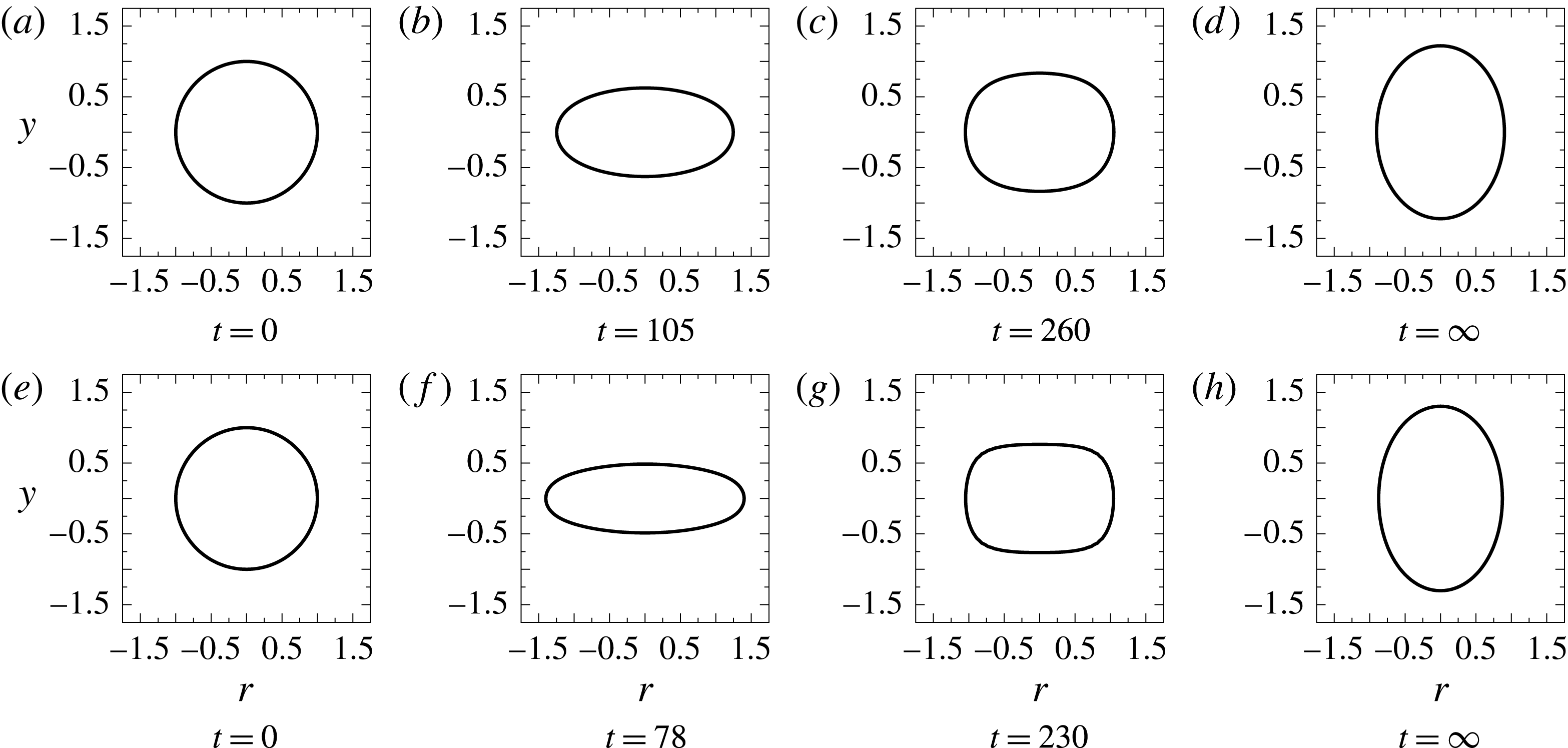
Shape evolution of a capsule with Skalak membrane at
 $\unicode[STIX]{x1D70E}_{r}=0.1$
for
 $Ca=0.25$
.

Intermediate shapes for the dynamics of the deformation of an elastic capsule from a spherical shape to the steady-state shape at
 $Ca=0.25$
are shown in figure 6 for
 $\unicode[STIX]{x1D70E}_{r}=0.1$
. While for
 $\unicode[STIX]{x1D70E}_{r}>1$
prolate shapes (figure 4
a–d) are observed, oblate shapes are seen (figure 6
b–d) for
 $\unicode[STIX]{x1D70E}_{r}<1$
until the membrane is fully charged. To understand this better, deformation studies at a still higher capillary number (
 $Ca=0.45$
) are conducted with an emphasis on
 $\unicode[STIX]{x1D70E}_{r}<1$
.
4.3 Dynamics of capsule deformation at large capillary number
4.3.1 Case of
$\unicode[STIX]{x1D70E}_{r}<1$

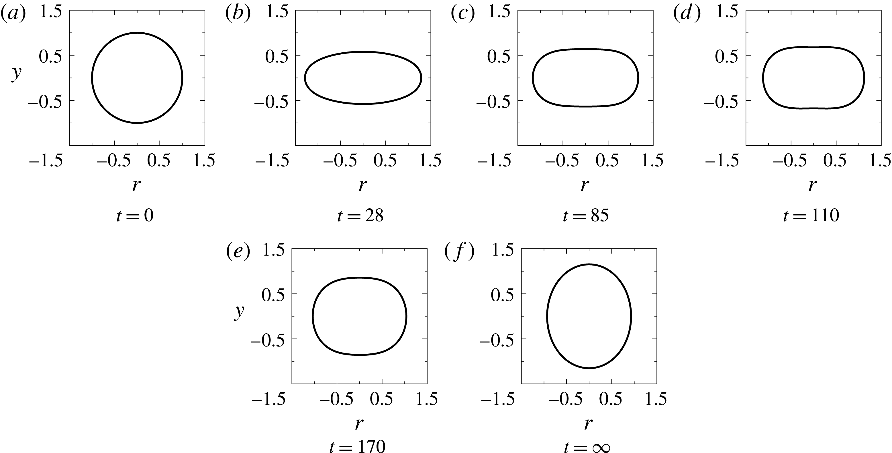
Shape evolution of a capsule with Skalak membrane at
 $\unicode[STIX]{x1D70E}_{r}=0.1$
for
 $Ca=0.45$
.

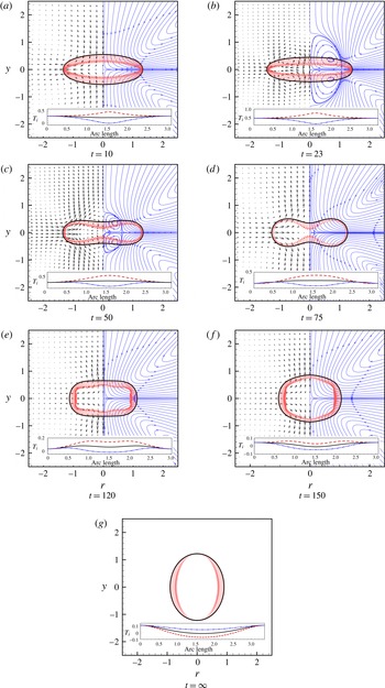
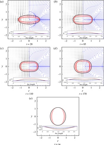
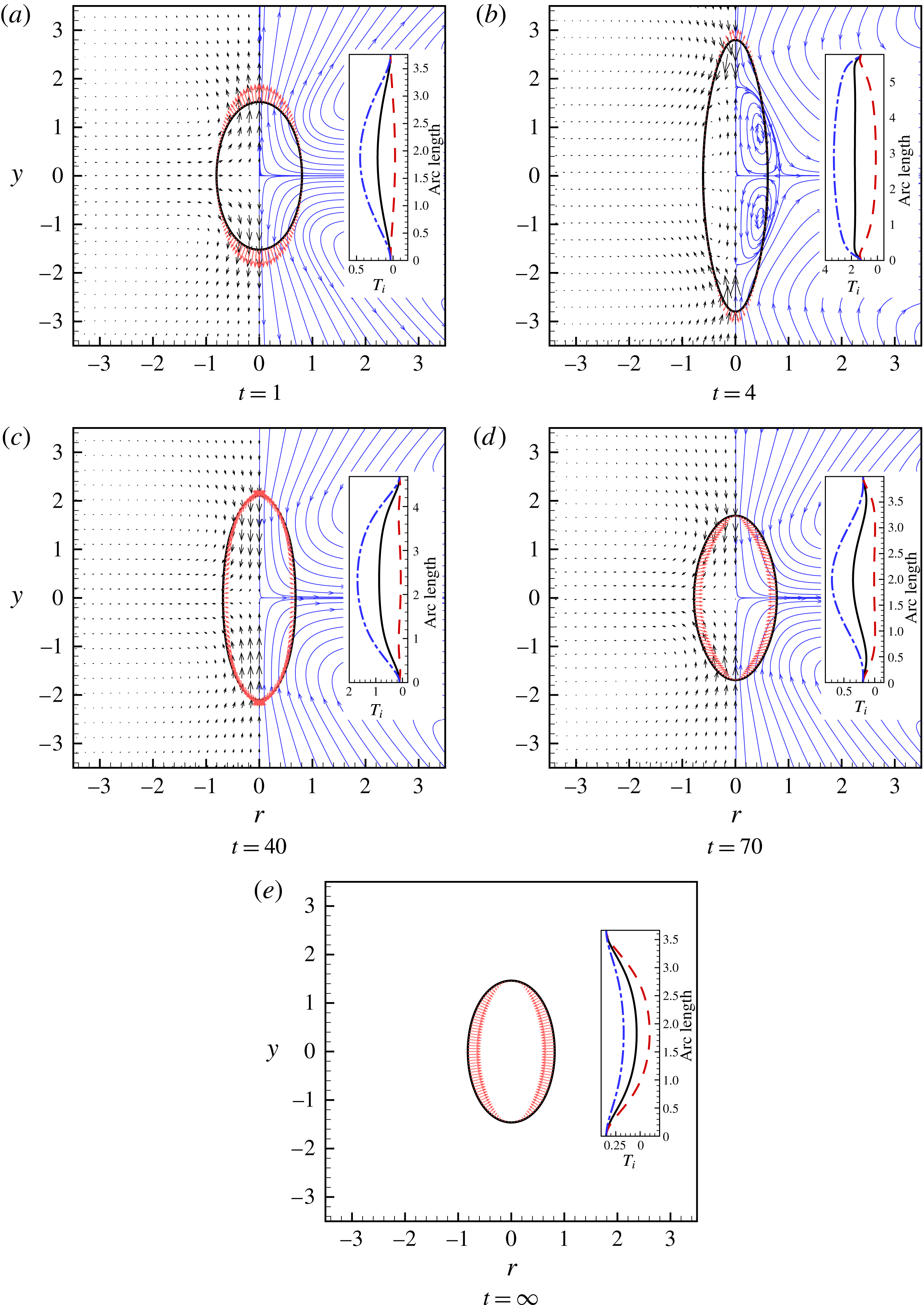
Streamline plot (curves with arrow, shown only at right side of axis of symmetry), velocity profile (short arrows, magnitude represents relative extent of flow, shown only at left side of axis of symmetry) and electric stress (arrows from the interface) for
 $Ca=0.45$
and
 $\unicode[STIX]{x1D70E}_{r}=0.1$
at different times. Inset shows the variation of meridional
 $T_{s}$
(— ⋅ —), azimuthal
 $T_{\unicode[STIX]{x1D713}}$
(– – –) and mean
 $T_{m}$
(——) membrane tensions along the arclength.

The temporal evolution of a spherical capsule with
 $\unicode[STIX]{x1D70E}_{r}=0.1$
at a high capillary number
 $(Ca=0.45)$
is shown in figure 7. In figure 8(a–g) electric tractions, streamlines and velocity profiles are shown for figure 7(b–h), respectively, and meridional elastic tension
 $T_{s}$
, azimuthal elastic tension
 $T_{\unicode[STIX]{x1D713}}$
and mean elastic tension
 $T_{m}=(T_{s}+T_{\unicode[STIX]{x1D713}})/2$
are shown in the insets. The same data for
 $Ca=0.25$
and
 $\unicode[STIX]{x1D70E}_{r}=0.1$
corresponding to figure 6(b–f) are shown in figure 9(a–e).
Figure 8(a) shows that the oblate shape at
 $\unicode[STIX]{x1D70E}_{r}=0.1$
is associated with compressive normal Maxwell stress such that their distribution is of the second Legendre kind; the flow is from poles to equator due to tangential stresses, thereby assisting the formation of oblate shapes. The elastic tensions (meridional and azimuthal) are tensile for oblate shapes at short times.
Figure 8(b) shows further increase in the oblate deformation of the capsule because the normal Maxwell stress is compressive such that it is maximum at the poles and minimum at the equator. However, importantly, an onset of flow reversal (flow from the equator to poles) is observed. A complex interplay of flow induced by both Maxwell stress as well as the elastic stress due to relaxation of the stretched capsule (indicated by the meridional tension also becoming tensile at the equator) leads to an initiation of biconcave shape formation of the capsule as shown in figure 8(c).
At
 $t=75$
, for
 $Ca=0.45$
, although the flow is from the equator to the poles, the large compressive normal Maxwell stress at the poles continues to bring together the poles, resulting in a biconcave shape (figure 8
d). The biconcave shape is necessary to generate enough curvature so that the elastic stresses can balance the electric stress. On the other hand, for
 $Ca=0.25$
, the compressive Maxwell stresses at the poles are not relatively high enough to cause a biconcave shape (figure 9).
For
 $Ca=0.45$
, at
 $t=120$
the charging of the membrane leads to substantial compressive electric stress at the equator, with a corresponding lowering of stress at the poles, which results in further squaring of the capsule (figure 8
e). This is indicated by a greater region of high azimuthal tension around the equator. A peak in the azimuthal tension is now seen at the shoulders. The depression of the biconcave shape relaxes since the normal Maxwell stress at the poles reduces. For biconcave, squaring and hexagonal shapes observed at intermediate times, the meridional tension is compressive at the equator while the azimuthal tension remains tensile. The relaxation of the poles continues at
 $t=150$
, leading to hexagonal shapes (figure 8
f). The shoulders seem to get arrested, probably due to the absence of electric stress, such that at
 $t=\infty$
the electric stresses are compressive, which, as discussed earlier, can be decomposed into an isotropic part and a tensile part
 $P_{2}(\cos \unicode[STIX]{x1D703})$
, which disappears at
 $54^{\circ }$
, resulting in a prolate shape (figure 8
g). In the case of
 $Ca=0.25$
though, the insufficient compressive electrical stresses at the poles lead to an absence of biconcave and hexagonal shapes (figure 9). This results in oblate shapes directly transforming into square shapes, wherein higher compressive electrical stress at the equator as compared to the poles leads to relaxation to a prolate steady-state shape. At the steady prolate shape, the azimuthal tension is compressive at the equator while meridional tension is tensile across the entire arclength (insets of figures 8
g and 9
e).
A similar study for a neo-Hookean capsule has been conducted and reported in the supplementary material (§ B.3). The salient features of the dependence of the deformation on the constitutive law of the membrane are (i) all the shapes observed for a Skalak membrane are also observed in the case of a neo-Hookean membrane, albeit at a lower
 $Ca$
, e.g. the deformation seen in Skalak membrane at
 $Ca=0.45$
is observed at
 $Ca=0.29$
for a neo-Hookean membrane when
 $\unicode[STIX]{x1D70E}_{r}=0.1$
, and (ii) a neo-Hookean membrane can undergo breakup (numerical) at a much lower
 $Ca$
number as discussed in § 4.5.
Streamline plot (curves with arrow, shown only at right side of axis of symmetry), velocity profile (short arrows, magnitude represents relative extent of flow, shown only at left side of axis of symmetry) and electric stress (arrows from the interface) for
 $Ca=0.25$
and
 $\unicode[STIX]{x1D70E}_{r}=0.1$
at different times. Inset shows the variation of meridional
 $T_{s}$
(— ⋅ —), azimuthal
 $T_{\unicode[STIX]{x1D713}}$
(– – –) and mean
 $T_{m}$
(——) membrane tensions along the arclength.

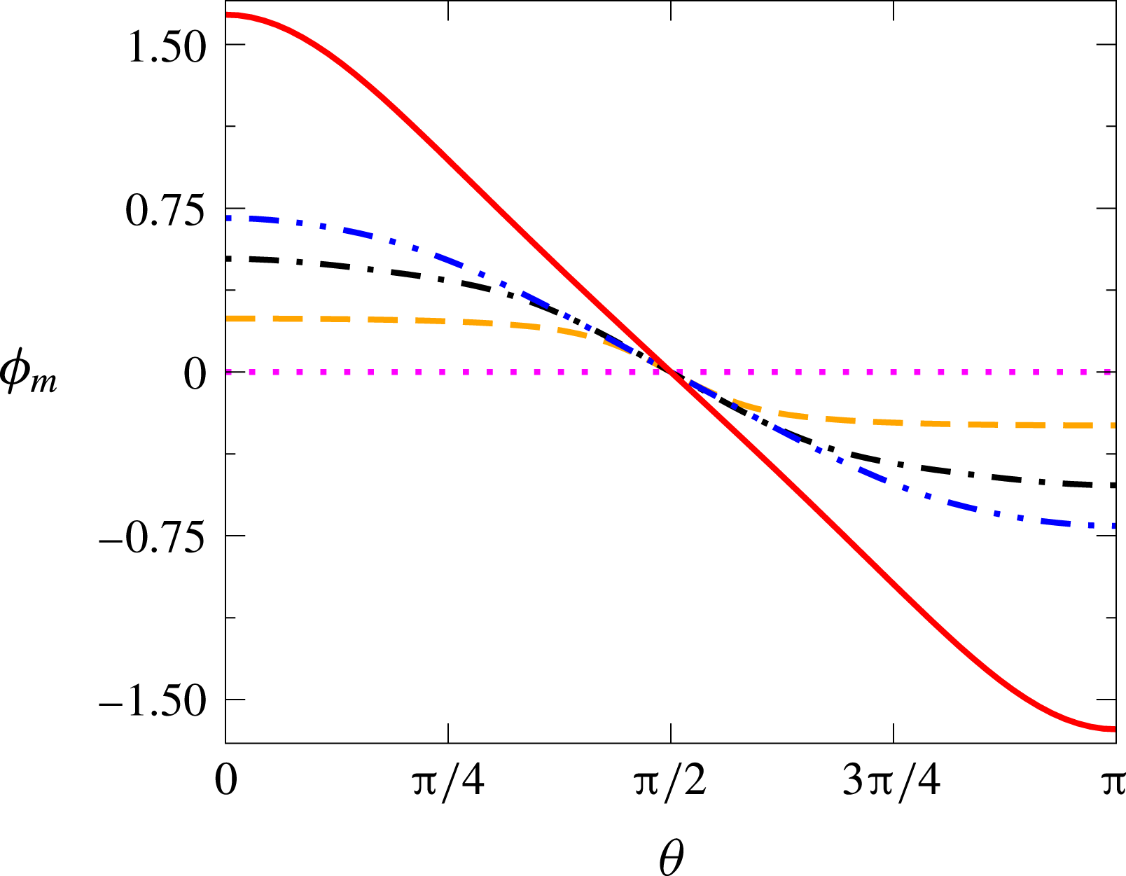
Variation of transmembrane potential on the interface (
 $\unicode[STIX]{x1D703}=0$
at north pole and
 $\unicode[STIX]{x1D703}=\unicode[STIX]{x03C0}$
at south pole) for the shapes at
 $t=0$
(⋯⋯),
 $t=50$
(– – –),
 $t=120$
(— ⋅ —),
 $t=230$
(— ⋅ ⋅ —) and
 $t=\infty$
(——) obtained during the deformation of a capsule at
 $Ca=0.45$
and
 $\unicode[STIX]{x1D70E}_{r}=0.1$
.

The variation of the transmembrane potential of the interface is shown in figure 10 for the intermediate shapes observed during the deformation of a capsule at
 $Ca=0.45$
and
 $\unicode[STIX]{x1D70E}_{r}=0.1$
. From figure 10 it can be observed that initially the capsule remains uncharged (
 $\unicode[STIX]{x1D719}_{m}=0$
at
 $t=0$
), then the transmembrane potential gradually increases, suggesting an increase in the charging of the membrane, and eventually at
 $t=\infty$
the membrane becomes fully charged. In all the cases, it can be observed that the poles always attain the maximum transmembrane potential, suggesting the possibility of electroporation at the poles. Moreover, the transmembrane potential at the poles is higher than
 $3/2$
at long times due to the deviation of the shape from sphericity.
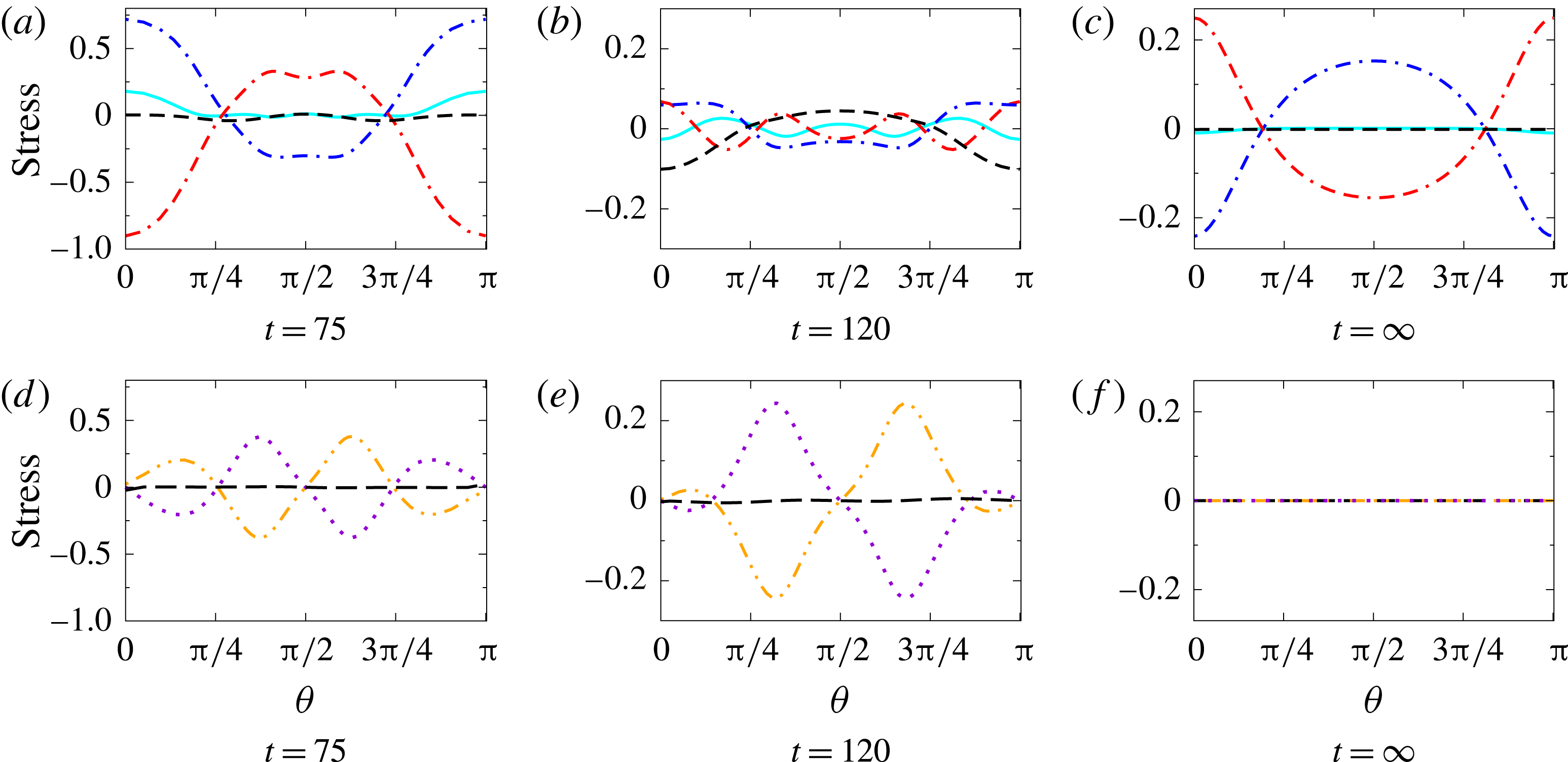
Variation of normal electric stress (– – ⋅ – –), normal elastic stress (— ⋅ —), normal hydrodynamic stress (– – –), stress due to bending rigidity (——), tangential electric stress (⋯⋯), tangential elastic stress (— ⋅ ⋅ —) and tangential hydrodynamic stress (— —) at the interface (
 $\unicode[STIX]{x1D703}=0$
at north pole and
 $\unicode[STIX]{x1D703}=\unicode[STIX]{x03C0}$
at south pole) for the (a,d) biconcave shape at
 $t=75$
, (b,e) square shape at
 $t=120$
and (c,f) steady prolate shape at
 $t=\infty$
in the deformation of a capsule at
 $Ca=0.45$
and
 $\unicode[STIX]{x1D70E}_{r}=0.1$
.

To understand the relative contribution of the membrane, hydrodynamic and electric stresses, figure 11 show these values in the case of a Skalak membrane where biconcave, square and steady-state prolate shapes are observed. In figure 11, the mean electric and elastic stresses are subtracted from their respective values. While in the biconcave case the hydrodynamic stress is minimal due to the onset of flow reversal, it is significant in the square shapes, indicating the role of hydrodynamic stress in shape transition from biconcave to spheroid. The hydrodynamic stress is absent in the steady-state prolate shape. Thus the normal as well as the tangential force balance is essentially a cancellation of the electric and membrane stresses. Among the membrane stresses, the bending contribution is seen in the biconcave and square shapes, whereas it is minimal in the steady prolate shape. The bending contribution is observed at regions of high curvature.
4.3.2 Case of
$\unicode[STIX]{x1D70E}_{r}>1$

Shape evolution of a capsule with Skalak membrane at
 $\unicode[STIX]{x1D70E}_{r}=10$
for
 $Ca=2$
.

In figure 12 the dynamics of a spherical capsule with a Skalak membrane at a high capillary number (
 $Ca=2$
) for
 $\unicode[STIX]{x1D70E}_{r}=10$
is shown. Unlike the case for
 $\unicode[STIX]{x1D70E}_{r}=0.1$
, and as discussed earlier, a capsule does not attain oblate intermediate shapes for
 $\unicode[STIX]{x1D70E}_{r}=10$
. Initially, because of high tensile electric traction, a capsule exhibits large prolate deformation (figure 13
a,b). Eventually, because of the compressive electric tractions (maximum at the equator and minimum at the poles) at long times, it relaxes back to a steady-state prolate shape (figure 13
e) through intermediate shapes shown in figure 13(c,d). At short times, the meridional and azimuthal tensions are tensile. While the meridional tension is maximum at the equator and smallest at the poles (figure 13
a,b), it is vice versa for the azimuthal tension. At intermediate times, azimuthal tension is negligible around the equatorial region. At steady state, the elastic tensions are similar to that at
 $\unicode[STIX]{x1D70E}_{r}=0.1$
. Simultaneously, the flow changes from equator to poles at short time (figure 13
a), from poles to equator at intermediate times (figure 13
b–d), and eventually disappears at long times (figure 13
e).
Streamline plot (curves with arrow, shown only at right side of axis of symmetry), velocity profile (short arrows, magnitude represents relative extent of flow, shown only at left side of axis of symmetry) and electric stress (arrows from the interface) for
 $Ca=2$
and
 $\unicode[STIX]{x1D70E}_{r}=10$
at different times. Inset shows the variation of meridional
 $T_{s}$
(— ⋅ —), azimuthal
 $T_{\unicode[STIX]{x1D713}}$
(– – –) and mean
 $T_{m}$
(——) membrane tensions along the arclength.

4.4 Effect of membrane capacitance, conductance and hydrodynamics on capsule deformation
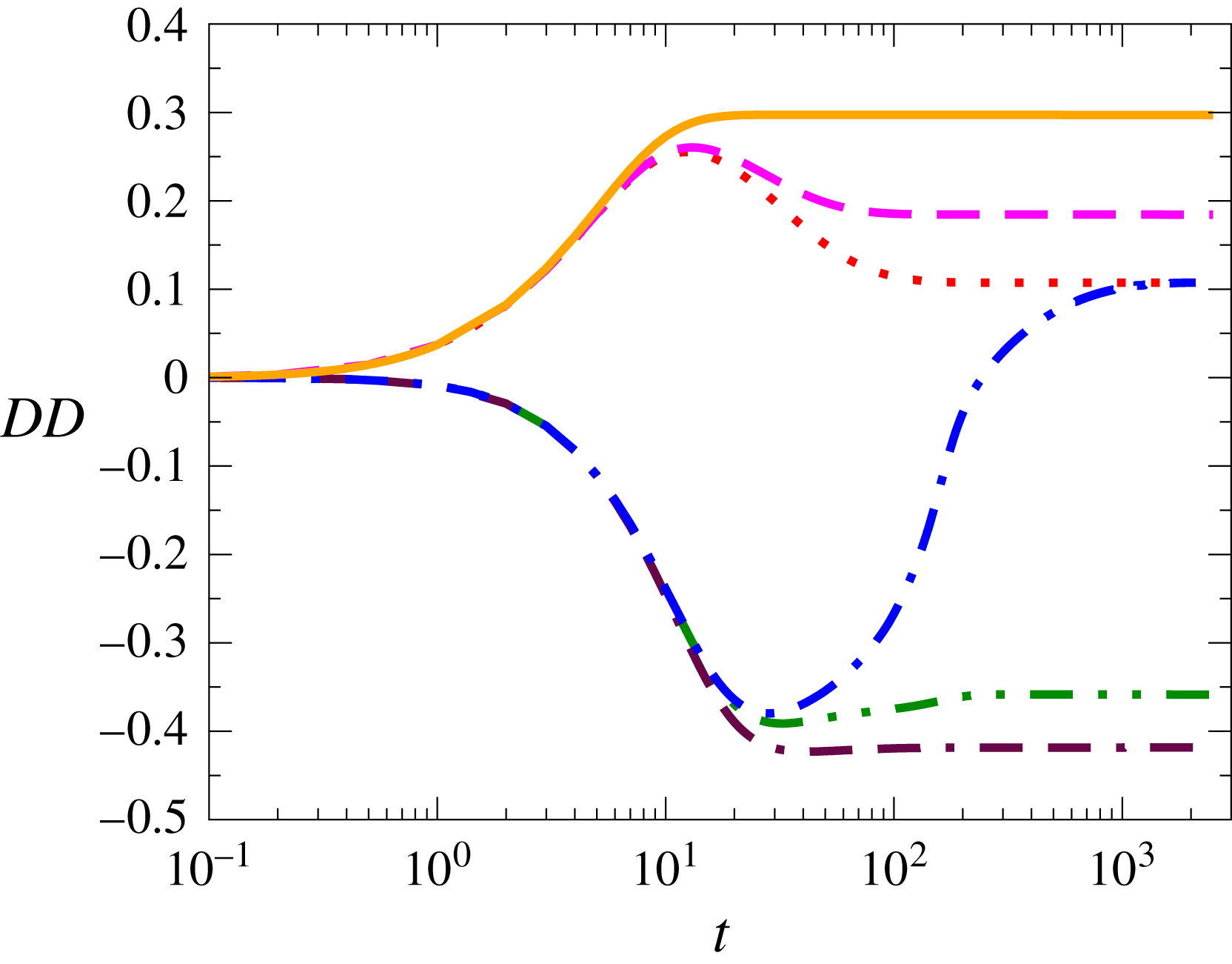
Effect of membrane capacitance on the dynamics of deformation of a capsule with Skalak membrane considering
 ${\hat{G}}_{m}=0$
at
 $Ca=0.25$
. Curves are:
 ${\hat{C}}_{m}=1$
(⋯⋯),
 ${\hat{C}}_{m}=50$
(– – –) and
 ${\hat{C}}_{m}=100$
(——) at
 $\unicode[STIX]{x1D70E}_{r}=10$
; and
 ${\hat{C}}_{m}=1$
(— ⋅ —),
 ${\hat{C}}_{m}=50$
(— ⋅ ⋅ —) and
 ${\hat{C}}_{m}=100$
(– – ⋅ – –) at
 $\unicode[STIX]{x1D70E}_{r}=0.1$
.

Shape evolution of a capsule with Skalak membrane at
 ${\hat{C}}_{m}=1$
for
 $\unicode[STIX]{x1D70E}_{r}=0.1$
and
 $Ca=0.45$
.

Figure 14 shows the effect of membrane capacitance on the degree of deformation of a capsule. As the capacitance increases, the response becomes slower, since the charging time increases. For
 $\unicode[STIX]{x1D70E}_{r}=10$
, where prolate deformation is expected, the peak deformation for higher capacitances is higher, because the continuity of ohmic current in the fluid and the displacement current in the membrane imply that the higher the capacitance, the higher is the normal electric field in the two fluids. This leads to higher Maxwell stress. A similar explanation can be provided for the oblate deformation observed when
 $\unicode[STIX]{x1D70E}_{r}=0.1$
. Moreover, as expected, the relaxation time is higher for higher capacitances. Lower capacitances also mean faster charging of the membrane, and higher membrane impedance at short times, which negate the drop-like behaviour of a capsule at short times, since
 $t_{cap}\sim t_{MW}\sim t_{H}$
. Very small oblate intermediate deformation is, therefore, observed at
 $\unicode[STIX]{x1D70E}_{r}=0.1$
, when
 ${\hat{C}}_{m}=1$
.
Figure 15 shows that the intermediate shapes obtained during the deformation of capsules with small capacitances are quite different compared to those for high capacitances. A capsule (
 $Ca=0.45$
and
 $\unicode[STIX]{x1D70E}_{r}=0.1$
) deforms into an oblate spheroid (figure 15
b) shape and through an intermediate near-spherical shape (figure 15
c) it reaches a steady-state prolate spheroid (figure 15
d). The absence of squaring is really due to the absence of high compressive electric stresses, observed in the high-capacitance case. This is because of the lower charging time at small capacitance, which leads to rapid charging of the membrane and thereby lower compressive Maxwell stress at the poles when the capsule is in oblate spheroid configuration. This prevents its evolution into a biconcave shape. The steady-state prolate shape is independent of the membrane capacitance. This suggests that, for admitting intermediate squaring and biconcave shapes, a sufficiently high capacitance of the membrane is essential.
Effect of membrane conductance on the deformation of a capsule with Skalak membrane considering
 ${\hat{C}}_{m}=50$
at
 $Ca=0.25$
. Curves are:
 ${\hat{G}}_{m}=0$
(⋯⋯),
 ${\hat{G}}_{m}=1$
(– – –) and
 ${\hat{G}}_{m}=10$
(——) at
 $\unicode[STIX]{x1D70E}_{r}=10$
; and
 ${\hat{G}}_{m}=0$
(— ⋅ —),
 ${\hat{G}}_{m}=1$
(— ⋅ ⋅ —) and
 ${\hat{G}}_{m}=10$
(– – ⋅ – –) at
 $\unicode[STIX]{x1D70E}_{r}=0.1$
.

The effect of membrane conductance on the degree of deformation is presented in figure 16. For
 $\unicode[STIX]{x1D70E}_{r}=10$
, showing prolate deformation, the steady-state deformation depends upon the membrane conductance. In the limit of the membrane conductance going to infinity, the steady-state deformation is the same as that of a liquid drop. Thus when
 $\unicode[STIX]{x1D70E}_{r}=0.1$
, the steady-state deformation can be oblate, especially at high membrane conductances (note that, for
 ${\hat{G}}_{m}=0$
, the steady-state deformation is always prolate), which corresponds to oblate deformation observed even in liquid drops. This is essentially due to a decrease in the membrane resistance and thereby the transmembrane potential going to zero.
For different values of membrane conductance, the dynamics (figure 16) as well as the final steady-state deformation and shapes are different (figure 17). For both the small (
 ${\hat{G}}_{m}=1$
in figure 17
a–d) and large (
 ${\hat{G}}_{m}=10$
in figure 17
e–h) membrane conductances, final steady-state oblate shapes are observed (
 $\unicode[STIX]{x1D70E}_{r}=0.1$
) unlike the prolate steady-state shapes for
 ${\hat{G}}_{m}=0$
.
Shape evolution of a capsule with Skalak membrane at
 $\unicode[STIX]{x1D70E}_{r}=0.1$
for
 $Ca=0.45$
and
 ${\hat{C}}_{m}=50$
for conducting membrane. Panels (a–d) represent shapes during deformation at
 ${\hat{G}}_{m}=1$
and panels (e–h) represent shapes during deformation at
 ${\hat{G}}_{m}=10$
.

Comparison of the numerical simulation results for the dynamics of capsule deformation with
 $t_{H}=10$
(– – –) and
 $t_{H}=1$
(——) for
 $Ca=0.45$
and
 $\unicode[STIX]{x1D70E}_{r}=0.1$
.

Shape evolution of a capsule with Skalak membrane at
 $\unicode[STIX]{x1D70E}_{r}=0.1$
,
 $\unicode[STIX]{x1D716}_{r}=1$
with
 $t_{H}=10$
for non-conducting membrane with
 ${\hat{C}}_{m}=50$
. Panels (a–d) represent shapes during deformation at
 $Ca=0.45$
and panels (e–h) represent deformed shapes at
 $Ca=0.8$
.

When the hydrodynamic response time
 $(t_{H})$
is greater than 1 (
 $t_{H}=10$
,
 $Ca=0.45$
and
 $\unicode[STIX]{x1D70E}_{r}=0.1$
are considered), a capsule undergoes much smaller intermediate deformation. Figure 18 shows that, although the membrane electrostatic stresses are high at
 $t\sim t_{e}$
, a sphere does not deform due to slow hydrodynamic relaxation. By the time the capsule shape responds to the stresses, the electric stresses themselves have already relaxed over time scales of
 $t\sim t_{cap}$
. Thus
 $t_{H}$
plays a critical role in the formation of biconcave intermediate shapes as well as squaring and hexagonal shapes discussed earlier. This is essentially due to the
 $t_{H}=t_{e}$
parameters chosen in those calculations. In that case, the shape responds instantaneously to the applied electric stress. Figure 19(a–d) shows that a capsule does not attain intermediate biconcave and hexagonal shapes. Moreover, the squaring also becomes less prominent. Even at very high capillary numbers such as
 $Ca=0.8$
(figure 19
e–h), biconcave and hexagonal intermediate shapes are not admitted, although squaring of the capsule is observed (figure 19
g). Further increase in capillary number results in failure of the boundary integral code on account of numerical stiffness at the corners of the square shapes due to high curvature.
4.5 Role of membrane constitutive equations and capsule breakup
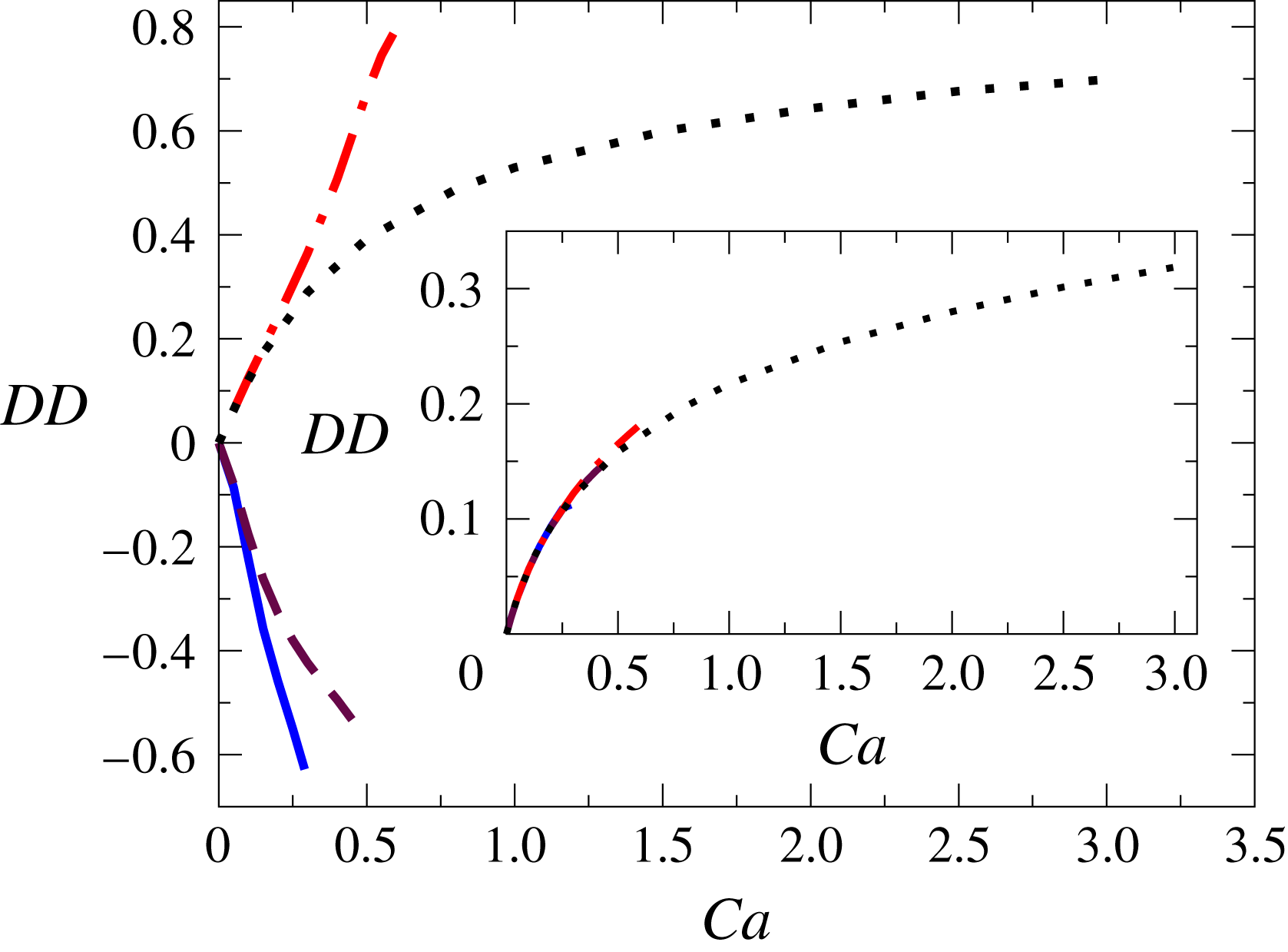
It is interesting to understand the role of constitutive equations and resulting membrane stresses in the deformation of a capsule. For
 $\unicode[STIX]{x1D70E}_{r}=0.1$
, capsules with a neo-Hookean membrane undergo a larger intermediate deformation compared to a capsule with a Skalak membrane (figure 20), even though the final steady-state deformations are the same at a particular capillary number (inset of figure 20). Capsules undergo breakup at the intermediate maximum deformation at
 $Ca=0.46$
for a Skalak membrane (figure 21
a) and at
 $Ca=0.3$
for a neo-Hookean membrane (figure 21
c); therefore the calculations cannot be continued further.
Intermediate maximum degree of deformation as a function of capillary number for a neo-Hookean membrane at
 $\unicode[STIX]{x1D70E}_{r}=10$
(— ⋅ —) and
 $0.1$
(——), and for a Skalak membrane at
 $\unicode[STIX]{x1D70E}_{r}=10$
(⋯⋯) and
 $0.1$
(– – –). Inset shows the degree of deformation at steady state as a function of capillary number for the corresponding cases.

Breakup shapes for a capsule with a Skalak membrane at (a)
 $Ca=0.46$
and (b)
 $Ca=30$
and a neo-Hookean membrane at (c)
 $Ca=0.3$
and (d)
 $Ca=0.6$
.

For
 $\unicode[STIX]{x1D70E}_{r}=10$
, at large capillary numbers, a neo-Hookean capsule shows strain-softening behaviour and undergoes very large maximum deformation, whereas a capsule with Skalak membrane shows strain-hardening behaviour in the maximum deformation as well as in the steady-state deformation (figure 20). A capsule with strain-hardening Skalak membrane does not show breakup for fairly high value of capillary number (numerical failure takes place at
 $Ca\sim 30$
) for
 $\unicode[STIX]{x1D70E}_{r}=10$
(figure 21
b), whereas a capsule with neo-Hookean membrane shows a numerical singularity, which is most likely a numerical artifact, at fairly low values of capillary number (
 $Ca=0.6$
as shown in figure 21
d).
5 Conclusions
Our analysis of an elastic capsule under an electric field indicates that several time scales,
 $t_{e}$
,
 $t_{cap}$
,
 $t_{MW}$
and
 $t_{H}$
, are involved in the deformation of an elastic capsule undergoing deformation in an applied uniform electric field. The fluids undergo a transition from perfect dielectrics to leaky dielectrics over time scale
 $t\sim t_{MW}$
, the capsule relaxes over time scale
 $t_{H}$
, whereas the capacitor is charged over time scale
 $t_{cap}$
, wherein it builds a transmembrane potential
 $\unicode[STIX]{x1D719}_{m}=3/2$
. An interplay of these time scales leads to a rich behaviour in the response of elastic capsules to DC fields. Experiments on capsules in DC fields can thus enable estimation of the electromechanical properties of these capsules.
Moreover, experimental analysis of a capsule in a millisecond to microsecond pulsed electric field should be able to show all the intermediate shape transitions. This can be easily seen since the typical time required for the shape transition, reported in this work, is of the order of the non-dimensional time
 $t=200$
and the considered time scale
 $t_{e}$
varies in the range of
 $10^{-5}$
–
 $10^{-7}~\text{s}$
, depending upon the conductivity of the external fluid. Further, for a capsule of
 $10~\unicode[STIX]{x03BC}\text{m}$
radius, the typical values of bending modulus
 $\unicode[STIX]{x1D705}_{b}=10^{-19}~\text{N}~\text{m}$
and elastic modulus
 $E_{s}=10^{-6}~\text{N}~\text{m}^{-1}$
(Pozrikidis Reference Pozrikidis2001) give rise to a non-dimensional bending modulus of
 $\hat{\unicode[STIX]{x1D705}}_{b}=10^{-3}$
. Therefore, the value of bending modulus used in this analysis is quite realistic. For other parameters, it could be considered to be a parameter that helps in numerical computation by eliminating numerical instabilities.
The predictions of highly nonlinear shapes such as squaring of capsules, akin to those seen in vesicles (in experiments and simulations) confirms the appropriateness of this model to predict deformation of capsules in high fields, such as in electroporation, which has technological relevance. This study also paves the way to understand the simultaneous deformation and breakup of more complex biological elastic capsules such as blood cells and will be a topic of a future study.
Acknowledgements
The authors would like to acknowledge the Department of Science and Technology, Government of India, for financial support for this work.
Supplementary material
Supplementary material is available at https://doi.org/10.1017/jfm.2018.89.
Appendix A. Analytical solution
Electrostatics and hydrodynamics of capsule deformation are solved analytically in the spherical coordinate system
 $(r,\unicode[STIX]{x1D703},\unicode[STIX]{x1D719})$
, where
 $r$
,
 $\unicode[STIX]{x1D703}$
and
 $\unicode[STIX]{x1D719}$
are the measurements of radial distance, meridional and azimuthal angles.
A.1 Solution for the deformation of a capsule
A.1.1 Simplified electrostatic model (SEM)
It is often a good approximation to neglect the displacement current in the two fluids since it is expected to be much smaller than the capacitive current of the membrane (
 $\unicode[STIX]{x1D716}_{e}/\unicode[STIX]{x1D70E}_{e}\ll 1$
and
 $\unicode[STIX]{x1D716}_{i}/\unicode[STIX]{x1D70E}_{i}\ll 1$
). In this case, the electrostatics equations reduce to
 $$\begin{eqnarray}\unicode[STIX]{x1D70E}_{r}E_{n,i}=E_{n,e}={\hat{C}}_{m}\frac{\text{d}\unicode[STIX]{x1D719}_{m}}{\text{d}t}+{\hat{G}}_{m}\unicode[STIX]{x1D719}_{m},\end{eqnarray}$$
and for a non-conducting membrane, the transmembrane potential is obtained as
 $$\begin{eqnarray}\unicode[STIX]{x1D719}_{m}={\textstyle \frac{3}{2}}(1-\text{e}^{-t/t_{cap}}),\end{eqnarray}$$
known as the Schwan equation (Grosse & Schwan Reference Grosse and Schwan1992), and the normal and tangential stresses are obtained as
 $$\begin{eqnarray}\unicode[STIX]{x1D70F}_{n}=\frac{9}{8}Ca\,\frac{4(\unicode[STIX]{x1D70E}_{r}^{2}-1)\text{e}^{-2t/t_{cap}}+[(5\unicode[STIX]{x1D70E}_{r}^{2}-8)\text{e}^{-2t/t_{cap}}+2\unicode[STIX]{x1D70E}_{r}(2+\unicode[STIX]{x1D70E}_{r})\text{e}^{-t/t_{cap}}-(2+\unicode[STIX]{x1D70E}_{r})^{2}]\sin ^{2}\unicode[STIX]{x1D703}}{(2+\unicode[STIX]{x1D70E}_{r})^{2}},\end{eqnarray}$$
 $$\begin{eqnarray}\unicode[STIX]{x1D70F}_{t}=\frac{9}{4}Ca\,\frac{(2+\unicode[STIX]{x1D70E}_{r}^{2})\text{e}^{-2t/t_{cap}}-\unicode[STIX]{x1D70E}_{r}(2+\unicode[STIX]{x1D70E}_{r})\text{e}^{-t/t_{cap}}}{(2+\unicode[STIX]{x1D70E}_{r})^{2}}\sin 2\unicode[STIX]{x1D703}.\end{eqnarray}$$
 $\unicode[STIX]{x1D708}_{s}=1$
), hydrodynamics and the solution methodology for the deformation of an elastic capsule are followed as reported by Thaokar (Reference Thaokar2016). The general expression for the degree of deformation is very large and complex. For
 ${\hat{G}}_{m}=0$
,
 ${\hat{C}}_{m}=50$
and
 $\unicode[STIX]{x1D716}_{r}=1$
, the degrees of deformation at different conductivity ratios are obtained as
 $$\begin{eqnarray}\displaystyle & & \displaystyle DD_{\unicode[STIX]{x1D70E}_{r}=0.1}=Ca[\!-0.000193+0.0882\text{e}^{(1/5)\sqrt{31/7}\,t}+0.703\text{e}^{(1/70)(21+\sqrt{217})t}\nonumber\\ \displaystyle & & \displaystyle \quad \qquad -\,2.125\text{e}^{((311+15\sqrt{217})/1050)t}+0.014\text{e}^{((313+15\sqrt{217})/1050)t}\! ]\text{e}^{-(1/70)(21+\sqrt{217})t},\end{eqnarray}$$
 $$\begin{eqnarray}\displaystyle & & \displaystyle DD_{\unicode[STIX]{x1D70E}_{r}=1}=Ca[\!-0.00504+0.319\text{e}^{(1/5)\sqrt{31/7}\,t}+0.703\text{e}^{(1/70)(21+\sqrt{217})t}\nonumber\\ \displaystyle & & \displaystyle \quad \qquad -\,1.122\text{e}^{((287+15\sqrt{217})/1050)t}+0.106\text{e}^{((301+15\sqrt{217})/1050)t}\! ]\text{e}^{-(1/70)(21+\sqrt{217})t},\end{eqnarray}$$
 $$\begin{eqnarray}\displaystyle & & \displaystyle DD_{\unicode[STIX]{x1D70E}_{r}=10}=Ca[\!-0.00344-3.775\text{e}^{(1/5)\sqrt{31/7}\,t}\nonumber\\ \displaystyle & & \displaystyle \qquad \quad +\,\text{e}^{(1/210)(49+3\sqrt{217})t}(4.887+0.333\text{e}^{(1/30)t}+0.703\text{e}^{(1/15)t})\!]\text{e}^{-(1/70)(21+\sqrt{217})t}.\nonumber\\ \displaystyle & & \displaystyle\end{eqnarray}$$
The dynamics of deformation of a capsule with Skalak membrane obtained from analytical theory considering the simplified electrostatic model (SEM), the boundary integral method considering simplified capacitor model (BEM-SM) and the boundary integral method considering capacitor model (BEM-CM) are compared at small capillary numbers (
 $Ca=0.01$
and
 $Ca=0.05$
) for the validation of the BEM-CM, which is used to study the dynamics of capsule deformation in this work. Considering
 $\unicode[STIX]{x1D716}_{r}=1$
,
 ${\hat{C}}_{m}=50$
and
 ${\hat{G}}_{m}=0$
, the dynamics are compared for
 $\unicode[STIX]{x1D70E}_{r}=1$
,
 $0.1$
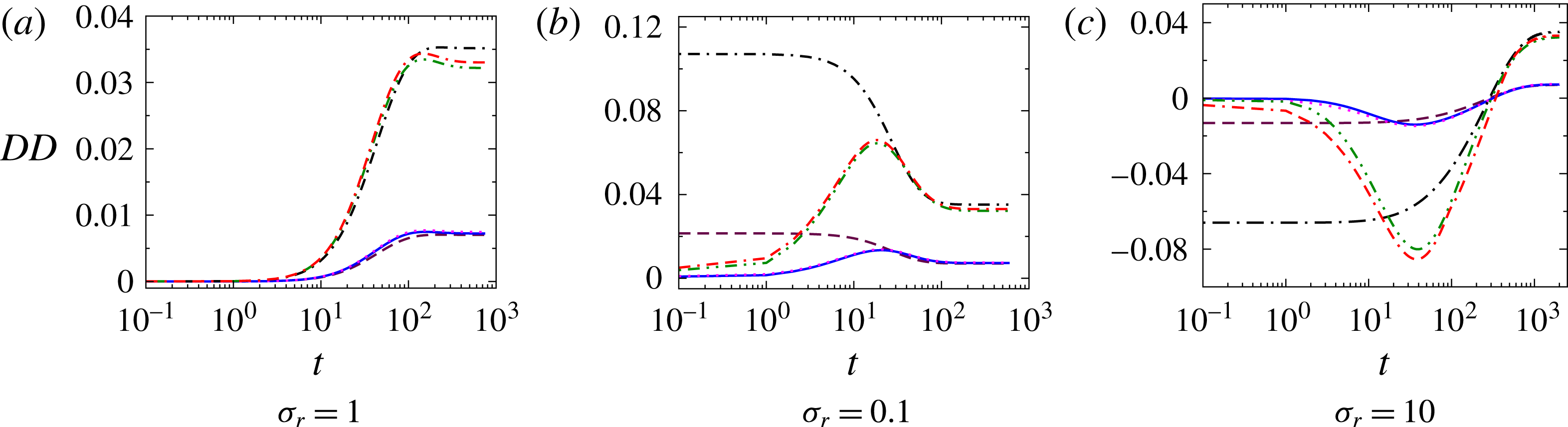
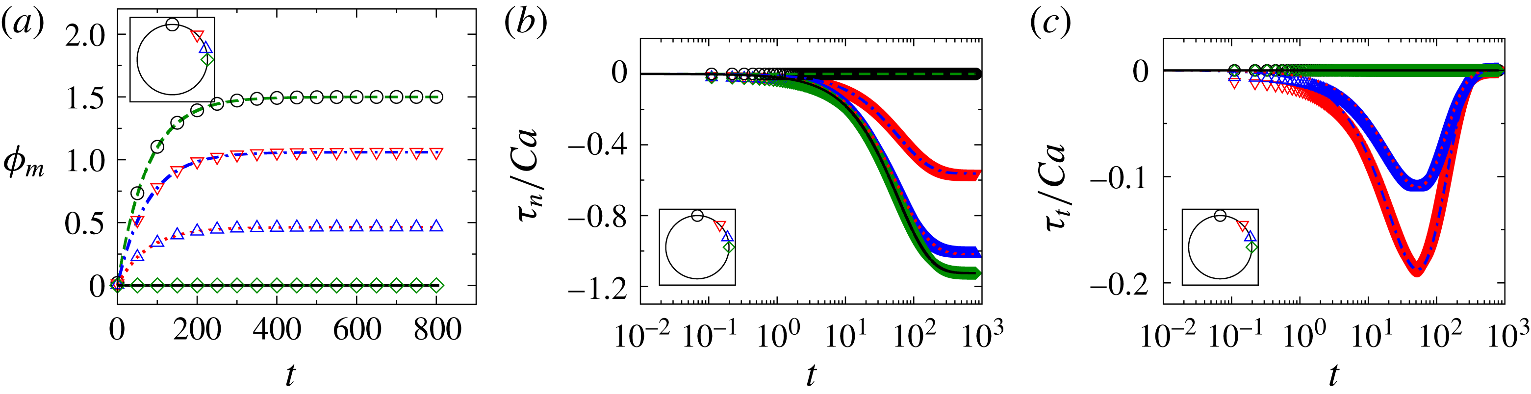
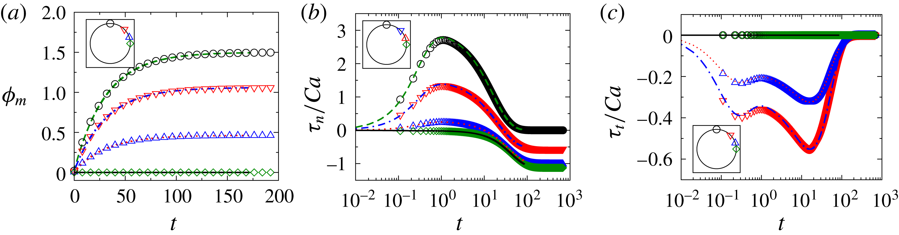
and
 $10$
in figure 22(a–c), respectively; a very good match is obtained between numerical and analytical values.
Comparison of dynamics obtained from SEM, BEM-SM and BEM-CM. At
 $Ca=0.01$
the dynamics are reported for SEM (– – –), BEM-SM (⋯⋯) and BEM-CM (——). At
 $Ca=0.05$
the dynamics are for SEM (— ⋅ —), BEM-SM (– – ⋅ – –) and for BEM-CM (— ⋅ ⋅ —).

A.2 Solution for the electrostatics
A.2.1 Analytical electrostatic theory (AET)
The external and internal potentials due to the applied uniform electric field of intensity
 $E_{0}$
of a spherical interface can be represented using spherical harmonics,
 $$\begin{eqnarray}\displaystyle \unicode[STIX]{x1D719}_{i} & = & \displaystyle A_{1}r\cos (\unicode[STIX]{x1D703}),\end{eqnarray}$$
 $$\begin{eqnarray}\displaystyle \unicode[STIX]{x1D719}_{e} & = & \displaystyle B_{1}\cos (\unicode[STIX]{x1D703})/r^{2}-r\cos (\unicode[STIX]{x1D703}),\end{eqnarray}$$
Comparison of numerically obtained (
 $\unicode[STIX]{x1D703}=0$
(○),
 $\unicode[STIX]{x03C0}/4$
(▿),
 $\unicode[STIX]{x03C0}/2.5$
(▵) and
 $\unicode[STIX]{x03C0}/2$
(♢)) and analytically obtained (
 $\unicode[STIX]{x1D703}=0$
(– – –),
 $\unicode[STIX]{x03C0}/4$
(— ⋅ —),
 $\unicode[STIX]{x03C0}/2.5$
(⋯⋯) and
 $\unicode[STIX]{x03C0}/2$
(——)) transmembrane potential (a), normal electric stress (b) and tangential electric stress (c) as functions of time for
 $\unicode[STIX]{x1D70E}_{r}=1$
.

where
 $A_{1}$
and
 $B_{1}$
are time-dependent coefficients of spherical harmonics. The time-dependent transmembrane potential is expressed as
 $$\begin{eqnarray}\unicode[STIX]{x1D719}_{m}=\unicode[STIX]{x1D719}_{amp}\cos (\unicode[STIX]{x1D703}),\end{eqnarray}$$
where
 $\unicode[STIX]{x1D719}_{amp}=\unicode[STIX]{x1D719}_{i}-\unicode[STIX]{x1D719}_{e}$
is the amplitude of the transmembrane potential. The current continuity condition across the membrane is expressed by
 $$\begin{eqnarray}\unicode[STIX]{x1D70E}_{r}E_{n,i}+\unicode[STIX]{x1D716}_{r}\frac{\text{d}E_{n,i}}{\text{d}t}=E_{n,e}+\frac{\text{d}E_{n,e}}{\text{d}t}={\hat{C}}_{m}\frac{\text{d}\unicode[STIX]{x1D719}_{m}}{\text{d}t}+{\hat{G}}_{m}\unicode[STIX]{x1D719}_{m}.\end{eqnarray}$$
In these non-dimensional equations, one can recall that
 ${\hat{C}}_{m}=C_{m}a/(\unicode[STIX]{x1D716}_{e}\unicode[STIX]{x1D716}_{0})$
and
 ${\hat{G}}_{m}=aG_{m}/\unicode[STIX]{x1D70E}_{e}$
. Solving (A 5) along with (A 6) and (A 7), the coefficients
 $A_{1}$
and
 $B_{1}$
are obtained; however, the analytical expressions are very large and cumbersome to evaluate. The internal and external normal electric fields are obtained as
 $$\begin{eqnarray}\displaystyle \boldsymbol{E}_{n,i} & = & \displaystyle -\boldsymbol{n}\boldsymbol{\cdot }\unicode[STIX]{x1D735}\unicode[STIX]{x1D719}_{i},\end{eqnarray}$$
 $$\begin{eqnarray}\displaystyle \boldsymbol{E}_{n,e} & = & \displaystyle -\boldsymbol{n}\boldsymbol{\cdot }\unicode[STIX]{x1D735}\unicode[STIX]{x1D719}_{e},\end{eqnarray}$$
 $$\begin{eqnarray}\displaystyle \boldsymbol{E}_{t,i} & = & \displaystyle -\boldsymbol{t}\boldsymbol{\cdot }\unicode[STIX]{x1D735}\unicode[STIX]{x1D719}_{i},\end{eqnarray}$$
 $$\begin{eqnarray}\displaystyle \boldsymbol{E}_{t,e} & = & \displaystyle -\boldsymbol{t}\boldsymbol{\cdot }\unicode[STIX]{x1D735}\unicode[STIX]{x1D719}_{e}.\end{eqnarray}$$
 $$\begin{eqnarray}\displaystyle \unicode[STIX]{x1D749}_{n}^{E} & = & \displaystyle {\textstyle \frac{1}{2}}Ca[(\boldsymbol{E}_{n,e}^{2}-\boldsymbol{E}_{t,e}^{2})-\unicode[STIX]{x1D716}_{r}(\boldsymbol{E}_{n,i}^{2}-\boldsymbol{E}_{t,i}^{2})],\end{eqnarray}$$
 $$\begin{eqnarray}\displaystyle \unicode[STIX]{x1D749}_{t}^{E} & = & \displaystyle Ca[\boldsymbol{E}_{n,e}\boldsymbol{E}_{t,e}-\unicode[STIX]{x1D716}_{r}\boldsymbol{E}_{n,i}\boldsymbol{E}_{t,i}].\end{eqnarray}$$
 $$\begin{eqnarray}\displaystyle f_{x}^{E} & = & \displaystyle \unicode[STIX]{x1D749}_{n}^{E}n_{x}+\unicode[STIX]{x1D70F}_{t}^{E}t_{x},\end{eqnarray}$$
 $$\begin{eqnarray}\displaystyle f_{y}^{E} & = & \displaystyle \unicode[STIX]{x1D749}_{n}^{E}n_{y}+\unicode[STIX]{x1D70F}_{t}^{E}t_{y}.\end{eqnarray}$$
 ${\hat{G}}_{m}=0$
,
 ${\hat{C}}_{m}=50$
,
 $\unicode[STIX]{x1D716}_{r}=1$
and
 $\unicode[STIX]{x1D70E}_{r}=1$
is obtained as
 $$\begin{eqnarray}\unicode[STIX]{x1D719}_{m}={\textstyle \frac{3}{2}}(1-\text{e}^{-t/76})\cos \unicode[STIX]{x1D703},\end{eqnarray}$$
and the normal and tangential stresses are obtained as
 $$\begin{eqnarray}\displaystyle \unicode[STIX]{x1D70F}_{n} & = & \displaystyle {\textstyle \frac{1}{8}}Ca(3\text{e}^{-t/38}\sin ^{2}\unicode[STIX]{x1D703}+6\text{e}^{-t/76}\sin ^{2}\unicode[STIX]{x1D703}-9\sin ^{2}\unicode[STIX]{x1D703}),\end{eqnarray}$$
 $$\begin{eqnarray}\displaystyle \unicode[STIX]{x1D70F}_{t} & = & \displaystyle -{\textstyle \frac{3}{4}}Ca(\text{e}^{-t/76}-1)\text{e}^{-t/38}\sin (2\unicode[STIX]{x1D703}).\end{eqnarray}$$
 $\unicode[STIX]{x1D70E}_{r}=0.1$
and
 $10$
the analytical solutions for the normal and tangential electrical stresses are very complicated and available in the supplementary material (§ B.4). Figures comparing results for transmembrane potential, tangential electric stress and normal electric stress obtained from analytical theory and boundary integral simulation can be obtained in § A.2.2 (figure 23
a–c for
 $\unicode[STIX]{x1D70E}_{r}=1$
, figure 24
a–c for
 $\unicode[STIX]{x1D70E}_{r}=10$
, and figure 25
a–c for
 $\unicode[STIX]{x1D70E}_{r}=0.1$
).
A.2.2 Validation of boundary integral code solving electric field
The boundary integral code with capacitor model (BEM-CM) to solve the electrostatics is validated by comparing results with the analytical electrostatic theory (AET) considering
 ${\hat{G}}_{m}=0$
,
 ${\hat{C}}_{m}=50$
and
 $\unicode[STIX]{x1D716}_{r}=1$
. The evolutions of transmembrane potential, normal and tangential stresses are shown in figure 23(a–c), respectively, for
 $\unicode[STIX]{x1D70E}_{r}=1$
, figure 24(a–c), respectively, for
 $\unicode[STIX]{x1D70E}_{r}=10$
and figure 25(a–c), respectively, for
 $\unicode[STIX]{x1D70E}_{r}=0.1$
.
Comparison of numerically obtained (
 $\unicode[STIX]{x1D703}=0$
(○),
 $\unicode[STIX]{x03C0}/4$
(▿),
 $\unicode[STIX]{x03C0}/2.5$
(▵) and
 $\unicode[STIX]{x03C0}/2$
(♢)) and analytically obtained (
 $\unicode[STIX]{x1D703}=0$
(– – –),
 $\unicode[STIX]{x03C0}/4$
(— ⋅ —),
 $\unicode[STIX]{x03C0}/2.5$
(⋯⋯) and
 $\unicode[STIX]{x03C0}/2$
(——)) transmembrane potential (a), normal electric stress (b) and tangential electric stress (c) as functions of time for
 $\unicode[STIX]{x1D70E}_{r}=10$
.

Comparison of numerically obtained (
 $\unicode[STIX]{x1D703}=0$
(○),
 $\unicode[STIX]{x03C0}/4$
(▿),
 $\unicode[STIX]{x03C0}/2.5$
(▵) and
 $\unicode[STIX]{x03C0}/2$
(♢)) and analytically obtained (
 $\unicode[STIX]{x1D703}=0$
(– – –),
 $\unicode[STIX]{x03C0}/4$
(— ⋅ —),
 $\unicode[STIX]{x03C0}/2.5$
(⋯⋯) and
 $\unicode[STIX]{x03C0}/2$
(——)) transmembrane potential (a), normal electric stress (b) and tangential electric stress (c) as functions of time for
 $\unicode[STIX]{x1D70E}_{r}=0.1$
.