


Introduction
The flow of glaciers is driven by gravity and opposed by resistive forces such that there is zero net force acting on any section of a glacier (inertial effects being negligible). The gravitational driving force is well understood but a major problem in understanding glacial flow is the proper identification and recognition of the sites of action of the resistive forces. These can act at the bed (basal drag), at the sides of a glacier or flow band (side drag), and longitudinally as pushes or pulls. The calculation of these resistive forces is an important component of the study of the flow and stability of glaciers.
This has been a long-standing problem in glaciology. Reference NyeNye (1957) calculated the shear stress at depth for the case of very simple bed configurations and plane flow. This approach was followed and improved upon by Reference RobinRobin (1967), Reference CollinsCollins (1968), Reference NyeNye (1969), Reference BuddBudd (1969, Reference Budd1970a, Reference Buddb), and Reference HutterHutter (1983), who incorporated the effects of gradients in longitudinal pushes and pulls. These studies show that basal resistive drag, τb, is linked to the driving stress, −⍴gH∂h/∂x with a correction for longitudinal gradients and a “variational” stress term, commonly denoted by T:

Here, x is directed along the flow and  represents the vertical mean longitudinal deviatoric stress. To calculate
 it is often assumed that the longitudinal strain-rate is independent of depth (Reference NyeNye, 1957; Reference MacAyeal, Bindschadler, Shabtaie, Stephenson and BentleyMacAyeal and others, 1987).
The T-term on the right-hand side of the above expression for basal drag is rather complex, involving the second derivative of the shear stress σxz,:
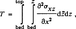
in which z represents the vertical coordinate. In most applications, the T-term is small and may be omitted from force-budget calculations (Reference HutterHutter, 1983; Reference Whillans and JohnsenWhillans and Johnsen, 1983; Reference Kamb and EchelmeyerKamb and Echelmeyer, 1986). The physical implications of omitting it are, however, not conceptually straightforward.
Further improvements in force-balance studies include side drag through a shape factor (e.g. Reference RaymondRaymond, 1980), or through another gradient term (Reference RaymondRaymond, 1980; Reference Bindschadler, Stephenson, MacAyeal and ShabtaieBindschadler and others, 1987; Reference Frolich, Mantripp, Vaughan and DoakeFrolich and others, 1987).
All previous investigations on the stress fields in glaciers rely on simplifying assumptions. For instance, the otherwise rigorous analysis of Reference Hutter, Legerer and SpringHutter and others (1981) is limited to cases in which the bottom and top surfaces deviate only slightly from straight parallel lines. Observations of real glaciers indicate, however, that the basal relief is often very large (10% or more of the ice thickness, over a horizontal distance of few kilometers). Similarly, the theory of Reference Kamb and EchelmeyerKamb and Echelmeyer (1986) is based on a linearization in which longitudinal variations in the ice flow are treated as small perturbations to the overall average flow. Also, longitudinal stresses are supposed not to contribute significantly to the effective stress. Longitudinal stresses in ice sheets are, however, very large and may play important roles.
Another major problem in the practical application of previous theories is that these require basal conditions to be known. In general, however, conditions prevailing at the base of a glacier (basal drag and sliding velocities) are not known and, with most existing methods, it is necessary to vary these conditions until an agreement between, for example, calculated and measured surface velocities is obtained. This makes the method of solution somewhat arbitrary and time-consuming.
What is needed is a method for using measurements of the surface effects of flow variations to calculate stresses and strain-rates at depth. In particular, the need exists to use measured data to calculate resistive stresses opposing the ice flow, and to identify the sites of stress concentration.
Earlier attempts to develop such a method are those of Reference Whillans and JohnsenWhillans and Johnsen (1983) and Reference Whillans and JezekWhillans and Jezek (1987). In these studies, basal conditions are not prescribed, but resistive stresses are calculated from measured surface-velocity and slope data. These methods, however, cannot treat power-law creep and are restricted to plane flow.
In this paper, a generally applicable method for the interpretation of field data in terms of the stress field is developed. First, the equations describing balance of forces are derived using the partitioning of full stresses into lithostatic and resistive parts (as in Reference Whillans and JezekWhillans (1987)). To relate these stresses to observable strain-rates, the constitutive relation is invoked and the balance equations are rewritten in terms of strain-rates. Approximate solutions can be readily obtained from these equations by making simplifying assumptions. Exact solutions require numerical techniques, which are explained in the second part of this contribution.
Deviatoric stresses are needed for the constitutive relation which links stresses to strain-rates. However, it is easier to understand force budget in terms of resistive stresses, because the use of deviatoric stresses can obscure the physical interpretation of calculated results. Deviatoric stresses are full stresses with the mean pressure removed, as called for by the constitutive relation. Deviatoric stresses thus include all three normal stresses. The force-balance equations are consequently more complex than when resistive stresses are used, except in the special case of plane flow. The partitioning of full stresses into lithostatic and resistive parts also allows a clearer distinction between action (driving stress) and reactions (gradients in resistive stresses). The action derives from gravity and the reactions from forces applied at the margins of the studied section of a glacier.
Our development follows closely the approach of prior work apart from the later introduction of deviatoric stresses and that boundary conditions at the upper surface are used instead of unknown basal conditions. Furthermore, there is no need to neglect the effects of the T-term, or “bridging effects”, as they are termed here. All stresses are included in the numerical calculation scheme and, as a result, the method is applicable to all glaciers: valley and outlet glaciers, ice shelves and ice streams, as well as inland ice.
Force Balance in Horizontal Directions
Consider the full stresses σij (i,j = x, y, z) acting on an element in the glacier with coordinate axes horizontal (x,y) and vertical (z). Balance of forces is expressed by:
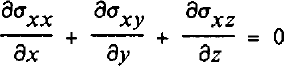
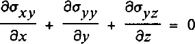

in which g represents acceleration due to gravity, and ρ ice density. Inertial forces are neglected.
Full stresses are partitioned into lithostatic (L) and resistive components (R ij):

where δ¡j is the Kronecker delta and ft represents the elevation of the upper surface of the glacier. R¡j represents elements of the resistive stress tensor and their net effect is to oppose the motion of the glacier.
Reference MacAyealMacAyeal (1987) used a very similar partition. He worked with quantities integrated through the thickness measured perpendicularly to the bed. His “dynamic drag” corresponds to our horizontal resistive stress, and his “form drag” to the lithostatic stress.
Separating full stresses into resistive and lithostatic components, the equations of horizontal force balance become:


Integrating from the base of a column (z = b) to the surface (z = h), one obtains:


The integration can be taken from any general depth to the ice surface, but as a start, force balance is calculated for the full thickness.
The order of integration and differentiation is now reversed and basal drag and driving stress are defined. Basal drag, τbi (i = x,y) includes all basal resistances:

and the driving stress is the familiar formula:

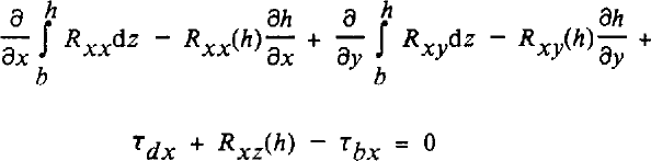
where xx = x and xy = y (Note that the driving stress does not act on a specific surface and so it is not a true stress; rather it is the net horizontal effect of gravity per unit area in map view.) One then obtains new balance equations from Equations (7) and (8):

The upper boundary conditions require a stress-free surface, which in terms of resistive stresses is (i = x,y):

This greatly simplifies the balance equations to:


Equations (14) and (15) are the basic equations needed for calculating basal drag from driving stress and resistive stresses acting on vertical surfaces. The first term represents the contrast in resistive forces acting on the x-faces of an ice column, the second term is the imbalance in resistive forces acting on the y-faces. The third term describes the action through the driving stress, and the last term is friction at the base of the glacier.
The balance equations as derived here have close affinities with the results of earlier developments (for example, Reference RaymondRaymond, 1980, equation (25)). Because no approximations are made in the above derivation, the balance Equations (14) and (15) are exact.
Bridging Effects
Because ice is very soft, the vertical normal stress is very nearly lithostatic and the vertical resistive stress, Rzz , is nearly zero. For simple calculations setting it to zero is appropriate, but this approximation need not be made in numerical computations.
Differences from lithostatic could be important at distances that are short compared to the ice thickness, or with certain special features such as ice falls. At small scales, part of the glacier can act like a bridge in which the vertical normal stress at the underside of the bridge span in less than the weight of ice above, while that under the abutment exceeds the weight of material above. This is illustrated in Figure 1. The variations in vertical normal stress from lithostatic lead to shear-stress gradients, as noted in the figure.
The bridging effect; vertical normal stresses are more compressive under the abutment and less compressive under the span. There are associated variations in shear stress

This topic has been discussed many times before by, among others, Reference BuddBudd (1970a), Reference HutterHutter (1983, p. 265), Reference Kamb and EchelmeyerKamb and Echelmeyer (1986), Reference NyeNye (1969), Reference Whillans and JezekWhillans (1987), and Reference Whillans and JohnsenWhillans and Johnsen (1983). These authors concur that bridging effects are important only on short-distance scales (a few ice thicknesses at most). Our results of force-budget calculations along the Byrd Station Strain Network (Reference Van der Veen and WhillansVan der Veen and Whillans, 1989; hereafter referred to as part II) confirm this conclusion.
Thus, for first-order calculations, bridging effects may be neglected and the vertical normal stress taken to be lithostatic, or equal to the weight of ice vertically above. In this approximation, the vertical resistive stress, Rzz = σzz - L is zero, and

Differentiating with respect to z gives:

Comparing Equation (17) with the third balance Equation(3) shows that neglecting bridging effects is equivalent to the assumption that horizontal gradients in the vertical shear stresses are small compared to pg. This is satisfied if 
When the balance equations are solved numerically, this approximation is not necessary, and the value of Rzz can be obtained from Equation (3) for vertical force balance. Separating the full stresses into resistive and lithostatic components, that equation becomes:

As before, the equation is vertically integrated, this time from a general depth z, to the surface, where the boundary condition is:

After reversing the order of integration and differentiation, the result is:

This expression, or the simplifying assumption Rzz = 0, is needed when force balance in terms of strain-rates is considered.
Relation between Resistive and Deviatoric Stresses
Constitutive relations generally link strain-rates to deviatoric stresses rather than to full stresses or resistive stresses. Deviatoric stresses are defined as full stresses minus the average normal stress (or spherical stress) which is supposed not to enter into the constitutive relation, except in a very minor way (for example, Reference HookeHooke, 1981). Consequently, the trace of the deviatoric stress tensor is zero as it is for the strain-rate tensor (for incompressibility), and the two can be readily linked. Therefore, to apply a constitutive relation of this type, it is necessary to write resistive stresses in terms of deviatoric stresses, σ'¡j
The two schemes for separating full stresses are:


in which the spherical stress is defined as S = (σ xx + σyy + σzz)/3.
Eliminating σ¡j from these expressions:

Taking i = j = z

because, by the definition, the normal deviatoric stresses must sum to zero. Substituting this into the expressions (22) provides resistive stresses in terms of deviatoric stresses:

(Recall that, for simple calculations, it is a good approximation to set Rzz = 0.)
Replacing resistive stresses with deviatoric stresses according to equation (24), the equation for force balance in the x-direction becomes:


These two balance equations are exact and neither the x-nor y-axis need follow a flow line.
By imposing more or less severe restrictions, the balance equations reduce to those of earlier developments. Setting Rzz = 0 is equivalent to neglecting bridging effects and the last term on the left-hand sides (corresponding to the T-term) vanishes. For the case of σ'xy = 0 = σ 'yy Equation (25) reduces to that derived in Reference NyeNye (1969). A valley “shape factor” is not included in equation (25) and (26); rather, the effect of side drag is included directly using side shear R or σ 'xy .
Application of Equation (25) or (26) need not be restricted to the flow of grounded ice. For instance, it is equally valid for ice shelves where basal drag is zero. Bridging effects can probably be neglected, and for an ice shelf in a parallel-sided bay, σ'yy = 0, and Equation (25) reduces to:

where the overbar denotes the vertical mean value, and H = h - b. In this, side-drag gradients are written as (Reference ThomasThomas, 1973a):

according to an approximation in which side drag is taken to vary linearly and W represents the half-width of the shelf. Equation (27) was used by Reference VeenVan der Veen (1987) in a numerical ice-shelf model. For interpretation of ice-shelf data, Reference ThomasThomas (1973b) used an x-integrated version of Equation (27) with sea-water pressure as a boundary condition.
Strain-Rates
The constitutive relation provides the linkage between deviatoric stresses and strain-rates. The most commonly used relation is due to Glen and Nye and reads (Reference PatersonPaterson, 1981, p. 30–31):

in which the exponent n is usually taken as equal to 3, and the stiffness parameter B is very sensitive to temperature. The effective strain-rate is:

This non-linearity in the constitutive relation is the principal reason why numerical techniques are best used.
The horizontal resistive stresses can be expressed in terms of strain-pates using the relations (24) and the constitutive relation (28). This gives:

In terms of strain-rates, force balance for the horizontal directions (Equations (25) and (26)) is thus expressed by:


These equations are used in the numerical solution scheme discussed below. If integrations in Equations (31) and (32) are carried out from a general depth z to the surface, rather than over the entire thickness, the balance equations allow calculation of strain-rates at all depths without making any ad hoc assumption about their vertical variation. The requirement for this calculation scheme is that surface velocities be measured, as well as the glacier’s geometry.
For simple, quick calculations simplifying assumptions can be made. Rzz can be set to zero and strain-rates can be held constant with depth at their surface values. This simple calculation is compared with a fuller calculation for Byrd Glacier in part III of this series (Reference Whillans, Chen, van der Veen and HughesWhillans and others, 1989). Although deep velocities cannot be calculated this way, the method yields deep stresses that are very similar to those obtained from the more exact calculation.
An account of the finite-difference solution scheme is given next, but in short, calculations start at the surface and proceed gradually downward (Fig. 2). At each depth, velocities at that depth and at all shallower strata are used to solve the balance equations for the shear strain-rates έxz and έ yz . These are used to calculate velocities at the next lower layer, and the calculations continue downward until the bed is reached.
Illustration of the solution scheme for calculating velocities and stresses at depth. Panel A shows the input data (surface slope, ice thickness, surface velocities) and geometry of the model. From the velocities, longitudinal strain-rates are calculated (panel B) and, invoking the surface-boundary conditions, shear stresses (panel C). From these, the vertical shear in velocity follows, and velocities at the next depth layer can be calculated (panel D). The vertical velocity follows from the stretching in panel B and incompressibility. The next steps are to calculate longitudinal strain-rates (panel E) and to solve the force-balance equation for shear stresses (panel F). This procedure is repeated for all depth layers (panel G). Finally, when the bed is reached, basal drag and stress normal to the bed are calculated (panel H)

Vertical Scaling for Numerical Calculations
The equations expressing balance of forces (Equations (31), (32), and (20)) are very non-linear and cannot be solved analytically without simplifications. A scheme for numerical solution is, however, readily constructed.
For clarity, plane flow in the (x,z)-plane is considered in the description, with the x-axis horizontal and along the mean direction of flow, and z vertically upwards. This simplification implies that strain-rate components involving the cross-flow, y-direction are zero, and also that force budget in this direction need not be considered. Extension of the methods developed here to include the second horizontal direction is straightforward, and in part III the results of a full three-dimensional calculation are presented.
The first step toward solving the balance equations numerically is to define a dimensionless coordinate to account for variations in thickness H = h - b, along the flow line;

At the surface, z = h and s = 0, whereas at the bed, z = h - H and j = 1. Using this vertical coordinate, the model domain becomes a rectangular two-dimensional grid.
In the (x,s) coordinate system, Equation (1) for force balance in the horizontal direction becomes

where

A derivation of the relation between horizontal gradients in the (x,z) coordinate system, and those in the (x,s) coordinate system, can be found in Reference HoltonHolton (1979, p. 21–22). Substituting the partitioning of full stresses into resistive and lithostatic components, and multiplying by H gives

Integrating this expression with respect to s, from a general depth, s, in the ice to the surface (s = 0) yields an equation for the shear stress at depth:

where the surface-boundary condition (13) has been used. This corresponds to Equation (14) and describes the balance of forces on a column from the surface to the level s.
To relate resistive stresses to observable velocities, the constitutive relation is used. From Equation (30) we find

and

Inserting these expressions into the balance Equation (36), force balance written in terms of strain-rates becomes
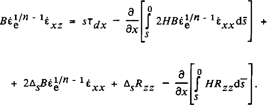
This is the basic equation used here. It allows calculation of the shear strain-rate, έχz , and hence the velocity variation with depth, for given driving stress, τdx , and longitudinal strain-rate, έχχ .
To calculate Rzz , Equation (20) describing force balance in the vertical direction is needed. Transforming this equation to the (x,s) coordinate system, and using Equation (38) to express Rxz in terms of strain-rates, the vertical balance equation becomes

Strain-rates are defined for the (x,z) coordinate system and these must be linked to the velocities which are computed in the (x,s) system. (Note, however, that the calculated velocities u and w are still parallel to the x- and z-axes, respectively; the coordinate transformation has not affected the directions of velocities, only the levels at which they are calculated.) This linkage to the (x,s) system makes the expression for strain-rate in the model domain somewhat more complex, but the benefits of using the (x,s) coordinate system are considerable.
The horizontal stretching rate in the (x,z) coordinate system is linked to velocity gradients through its definition:

and considering that the differential, du, can be written as

the horizontal stretching rate becomes:

The value of [∂s/∂x]z is obtained from the definition of s and using it gives

This cannot be solved directly because [∂u/∂s]x is related to έχz, and that is unknown until the balance Equation (39) is solved.
The relation between [∂u/∂s\x and ixz is obtained from the definition of the shear strain-rate:

In terms of gradients in the (x,s) coordinate system, the first term in the large brackets is:

The second term can often be neglected, especially when surface slopes are small, but that is not necessary. Following a development similar to that for έxx above, one obtains:

In this expression, the vertical derivative [∂w/∂s]x is linked to vertical strain-rate, and hence, because ice is incompressible, to horizontal strain-rate:

From Equation (42) we find

Substituting Equation (44) into Equation (41), the longitudinal strain-rate becomes:

This relation is used to solve the balance Equation (39). It relates the stretching έxx to the velocity gradients [∂u/∂x] and [∂w/∂x]s which are taken along surfaces of s = constant, and to the shear strain-rate έxz . In a similar fashion, the vertical resistive stress Rzz can be expressed in terms of these velocity gradients and ζxz . Thus, provided velocities at some depth s and above are known, the balance Equation (39) contains just one unknown, the shearing έxz, and therefore it is solvable by means of iteration, as discussed in the next section.
Numerical Solution
The focal point of the numerical scheme is solving the balance Equation (39) for the shear strain-rate έxz at general depth, s. As noted above, the solution can only be found after velocities at that depth layer, and at layers above, have been calculated. This means that calculations must start at the surface, where measured velocities are available, and proceed gradually downward, until the bed is reached.
The geometry of the numerical model is shown in Figure 2, panel A. Horizontal grid points are denoted by /, and depth layers by j, with j = 1 at the surface (where s = 0) and increasing downward to a maximum of j = J. The equations derived in the preceding section are readily transformed to this numerical grid using standard finite-difference methods (for example, Reference SmithSmith (1985), which also contains a discussion of round-off errors involved in this transformation).
Strain-rates at the surface are obtained from velocity gradients measured along the j = 1 (or s = 0) surface. Using the constitutive relation, the surface boundary condition (13) can also be written as

and combining with Equation (45) gives the horizontal stretching:

After calculating έ xx (ί,1), vertical shearing follows from Equation (46) and the vertical strain-rate from incompressibility:

Velocity change with depth for the surface stratum can now be calculated from Equation (44)

and from Equation (43)

Approximating the derivatives by forward differences, velocities at the second layer (j = 2) are:

where Δz(i) = H(i)/(J - 1) represents the vertical spacing between two adjacent layers.
Although έxz does not vary very much with depth near the surface, using Equation (48) can result in an over-or under-estimation of velocities at the second depth layer. Therefore, a two-step loop is included in the present model. First, all strain-rates at level j = 2 are calculated using the balance Equation (39), together with the velocities following from Equation (48). Next, improved values for these velocities are computed from central differencing

and these values are used to repeat the stress calculations at level j = 2.
At deeper layers (j ≥ 3) velocities can be calculated using central differencing:

However, applying Equation (50) to calculate u(i,j) can lead to “leap-frogging” velocities, with large values at odd levels and small values at even levels, or vice versa. Therefore, velocities are calculated using central differencing involving two higher layers.
The vertical gradient at the intermediate level, j - 3/2, is given by

and also by

Setting the right-hand sides equal:

Eliminating u(i,j - 2) from Equations (50) and (51) gives:

A similar expression is used to calculate the vertical velocity w(i,j)
The next step is to solve the balance Equation (39). Writing this equation for brevity as

where F represents the right-hand side of Equation (39) divided by  A simple iteration scheme is used to find the solution, and this can be represented by:

in which superscripts denote the iteration steps. As an initial guess, the value of the layer above is used:

The solution scheme is summarized in Figure 2. Because the velocities at level j are known (panel D), longitudinal stretching (panel E) can be calculated from Equation (45), using Equation (55) for the shearing term. Similarly, Rzz can be expressed in terms of known velocity gradients and the unknown έxz, using Equation (40). Substituting these estimates in the right-hand side of the balance Equation (53) yields an improved value for έx and Rzz . Although the iteration is somewhat complicated because the balance Equation (53) also contains horizontal derivatives, convergence occurs rapidly. Taking as the convergence criterion that the relative difference between two subsequent calculations of εxz must be less than 0.1% along the entire flow line, the number of iteration steps is typically two near the surface, and five near the bed (where έxz varies more strongly with depth).
One may note that the calculation scheme can be inverted to start at the base and progressively work upward to the surface. Basal velocities must be specified, as well as the geometry of the section of glacier. Calculated results are basal drag and surface velocities. This procedure is described by Reference Van der VeenVan der Veen (in press).
Concluding Remarks
The equations for force balance can be applied to the evaluation of the force budget of any glacier if the constitutive relation is prescribed. The scheme includes effects of lateral and longitudinal convergence or divergence of ice flow and of varying side drag along the glacier. The scheme also applies regardless of the azimuth of the horizontal coordinate axes, and thus is very useful for realistic situations in which the ice flow changes direction. Furthermore, the equations apply to floating ice (zero basal drag) as well as to grounded ice, and so a single set of equations can be used for glaciers that are partially afloat.
The calculation scheme presented here is straightforward and free from restrictive mathematical assumptions. Provided surface slopes, horizontal velocities at the ice surface, and ice thicknesses are known, stresses at all depths are calculated explicitly, without making a priori assumptions about velocity or stress variation with depth. In its finite-difference formulation, the solution scheme is very fast. A calculation on a horizontal grid with 47 grid points and 101 depth layers (for the Byrd Station Strain Network, in part II) requires about 15 min on an early model IBM-AT personal computer.
The primary motivation for this program is the availability of repeat photogrammetry of glaciers and the possibility of measuring hundreds of surface velocities distributed over a glacier. Most notably, such measurements have been carried out for Columbia Glacier (Reference Meier, Rasmussen, Krimmel, Olsen and FrankMeier and others, 1985), Byrd Glacier (Reference BrecherBrecher, 1986), Ice Stream B (Reference Whillans and BindschadlerWhillans and Bindschadler, 1988), and Jakobshavns Isbras (personal communication from H.H. Brecher). In part III (Reference Whillans, Chen, van der Veen and HughesWhillans and others, 1989), force-budget calculations for full three-dimensional flow of Byrd Glacier are discussed.
The method of calculating deep stresses can also be applied to smaller strain grids. Part II (Reference Van der Veen and WhillansVan der Veen and Whillans, 1989) applies the numerical solution scheme developed here to the flow along the Byrd Station Strain Network and discusses how the results are affected by uncertainties in the input data.
Acknowledgements
This work was supported by U.S. National Science Foundation grant DPP–83117235 and a Post-Doctoral Fellowship from The Ohio State University. We thank J. Bolzan, K. Hutter, and a referee for comments. Figures are by R. Tope and typing is by K. Doddroe and C Kinzelman. This is Byrd Polar Research Center contribution number 598.



