I. INTRODUCTION
In recent years, new innovative magnesium alloys have attracted a lot of attentions as potential load-bearing bioimplant materials due to their excellent mechanical properties, biocompatibility as well as biodegradability. Reference Witte, Fischer, Nellesen, Crostack, Kaese, Pisch, Beckmann and Windhagen1,Reference Staiger, Pietak, Huadmai and Dias2 Magnesium alloys have relatively low elastic modulus that is much closer to that of natural bones than currently traditional metallic materials, which could minimize or even avoid stress shielding effect. Reference Shadanbaz, Walker, Staiger, Dias and Pietak3 With all of these special properties, magnesium and its alloys become promising candidates and are widely studied for biomedical implant applications. However, magnesium alloys could be degraded in physiological environment, which makes the secondary surgery as well as the problems caused by the surgery avoidable. Considering magnesium alloys are biodegradable in the body, the corrosion products are expected to be not deleterious to the surrounding tissues.
Nevertheless, the problems impeding magnesium alloys’ application in biomedical field still exist, the most prominent one is that magnesium alloys corrode so fast in physiological environment that they lose the required mechanical integrity before the damaged tissues have healed. Reference Zeng, Dietzel, Witte, Hort and Blawert4 The rapid corrosion of magnesium alloys in physiological environment may cause some problems concerning reliability of implants for load-bearing applications. Thus, it is desirable to have an initial fixation and a predictable degradation adapted to the bone healing process for load-bearing implants. Reference Waizy, Weizbauer, Modrejewski, Witte, Windhagen, Lucas, Kieke, Denkena, Behrens and Meyer-Lindenberg5 Once implanted into body tissues, biomedical implant will be immersed in physiological environment, and the in vivo corrosion begins. As load-bearing applications, biomedical implants that function as bone plates and vascular stents would be in service under complex loading conditions, thus, cyclic loading conditions, including compression, tension, and bending, would be common. Reference Gu, Zhou, Zheng, Cheng, Wei, Zhong, Xi and Chen6 Therefore, many researches concerning fatigue failure of magnesium alloys with and without physiological environment were carried out. Zhao et al. Reference Zhao, Gao, Gao, Yuan and Chen7 studied fatigue life of ZEK100 magnesium alloy after corrosion in simulated physiological environment, found that the fatigue life of the specimens decreased with the increase of the immersion duration. Fu et al. Reference Fu, Gao, Chen, Gao and Chen8 studied the fatigue life and deterioration of mechanical for precorroded AZ31 sheet, found the precorroded damage have negative effect on elastic modulus and the elongation of AZ31 sheet and the fatigue life decreased obviously. Lin et al. Reference Lin, Chen, Liu and Chen9,Reference Chen, Lin and Chen10 investigate the low-cycle fatigue behavior of AZ91 magnesium alloy by asymmetric cyclic stress-controlled tests, and the effects of stress ratio, peak stress on residual twins, and the lifespan were analyzed. Waizy et al. Reference Waizy, Weizbauer, Modrejewski, Witte, Windhagen, Lucas, Kieke, Denkena, Behrens and Meyer-Lindenberg5 examined the mechanical properties of ZEK100 plates via four-point bending experiments after 14, 28, and 42 days of immersion. Lin et al. Reference Lin, Liu, Chen and Chen11,Reference Lin, Liu, Chen and Chen12 studied the uniaxial and low-cycle fatigue behaviors of AZ31B and the effects of serval stress parameters, according to the results a stress-based fatigue life prediction models was proposed. When implants subjected to a cyclic loading with nonzero mean stress, an accumulation of plastic deformation will occur if the stress is higher than yield strength (YS), which is known as ratcheting effect. Ratcheting effect induces not only large plastic deformation but also fatigue damage on the material and thereby the fatigue life of materials is affected, therefore, it is necessary to investigate the ratcheting behavior of magnesium alloys under different loading conditions and surrounding environments. A lot of studies about ratcheting evolutions were reported in earlier researches. A. Varvani-Farahani et al. Reference Ahmadzadeh and Varvani-Farahani13 formulated the ratcheting strain evolution of several typical steel alloys by means of linear and nonlinear functions. The functions, which are defined based on the stress level and mechanical properties of materials, can predict ratcheting strain values very well. In another research, A. Varvani-Farahani et al. Reference Varvani-Farahani14 focused on studying the model description of ratcheting assessment and hardening rules over asymmetric stress cycles, and compared the serval typical hardening rules in prediction of ratcheting curve with experiments data. And the results have significant influence on the studies in this field.
The present investigation was initiated to explore the uniaxial ratcheting behaviors of ZEK100 magnesium alloy. Emphasis was placed on evaluating the effects of several factors, including mean stress, stress amplitude, specimen orientation, loading history, and precorroded duration. Tensile tests and immersion tests were conducted to obtain the mechanic properties and corrosion rate of material. Optical microscope (OM) and scanning electron microscope (SEM) were used for metallographic observation and postcorroded surface analysis, respectively.
II. MATERIAL AND EXPERIMENTS
A. Material preparation
The experimental material used for investigation is commercial hot-rolled ZEK100 magnesium alloy plate, which was purchased from Guangdong Ruiheribiao metallic material Co. (Dongguan, China). The composition of the material is shown in Table I. The dog-bone flat specimens with a rectangular cross section of 3 mm × 2 mm and a gauge length of 15 mm along the transverse direction (TD) and rolling direction (RD) were prepared for tensile, immersion, and ratcheting testing.
Chemical composition of ZEK100 alloy (wt%).

B. Tension tests
To investigate the anisotropy of ZEK100 rolling plate tension tests for specimens of rolling direction (RD) and transverse direction (TD) were performed at a displacement rate of 0.1 mm/s by the In situ Bi-directional Tension & Compression Testing System (IBTC-5000, CARE Measure & Control, Tianjin, China) at room temperature. The measuring ranges of loading and displacement for the IBTC-5000 are 0–5000 N and 0–70 mm, respectively. The loading frequency is 0.01–1 Hz. The loading accuracy is 0.3% of measuring range, and the displacement accuracy is 0.1 μm. In this study, the axial strain was measured by an extensometer.
C. Immersion test
The immersion tests were conducted in a water bath maintained at a temperature of 37 ± 0.5 °C. The medium used in the immersion tests was phosphate buffered solution (PBS) Reference Xin and Chu15 whose composition is given in Table II. PBS can provide a good simulation of body fluid due to the nearly identical Cl ion concentration to physiological environment and the pH level of 7.4 (Ref. Reference Fu, Gao, Chen, Gao and Chen8). The immersion tests were carried out according to the ASTM standard G31-72 for different durations: 1 day, 3 days, 7 days, and 14 days. Before immersion tests, all the surface of the specimens should be treated. The surface treatment process followed the preparation procedure of Ref. Reference Fu, Gao, Chen, Gao and Chen8. Then the specimens were weighed by electronic balance. To maintain the stability of pH in the vicinity of samples, the ratio of the volume (mL) of PBS to the surface area (cm2) of samples should be no less than 10. 55% of solution was renewed every 24 h to simulate the metabolism of human body. The pH value of the solution was measured with pH meter before renewing to monitor the buffering capability of PBS. After immersion, specimens for corrosion rate calculation were soaked in chromate acid (200 g/L CrO3 and 10 g/L AgNO3) for 6 min to remove the corrosion products and then rinsed with distill water. Reference Gao, Zhang, Zhao, Gao and Li16 After dried in air, the specimens were weighed by the electronic balance. The methods to evaluate the corrosion rate in vitro mainly include electrochemical tests, hydrogen evolution, and mass/volume loss after immersion tests. Reference Sanchez, Luthringer, Feyerabend and Willumeit17 The method used in this study is mass loss method which is easily performed, and the corresponding equation is given as follows Reference Fu, Gao, Chen, Gao and Chen8,Reference Gao, Zhang, Zhao, Gao and Li16,Reference Sanchez, Luthringer, Feyerabend and Willumeit17 :
 $${\rm{CR}} = {{\Delta W} \mathord{\left/ {\vphantom {{\Delta W} {\left( {At} \right)}}} \right. \kern-\nulldelimiterspace} {\left( {At} \right)}}\quad ,$$
where CR is the corrosion rate in g/(m2 d), ΔW is mass loss in g, A is the original surface area exposed to the solution in m2, and t is the time of immersion in days.
Chemical composition of PBS (g/L).

D. Ratcheting tests
Asymmetrical multistep stress-controlled ratcheting tests were conducted on original and per-corroded specimens at room temperature using IBTC-5000. The stress-controlled experiments were carried out by using triangle waveform with a constant stress rate of 100 MPa/s. The axial nominal strain was measured by an extensometer. Due to the existence of mean stress, an accumulation of plastic strain occurs in the direction of the mean stress, which is known as the ratcheting strain, the value is defined as follows:
 $${\varepsilon _{\rm{r}}} = {{{\varepsilon _{\max }} + {\varepsilon _{\min }}} \over 2}\quad ,$$
where εmax and εmin are the maximum and minimum axial strain in each cycle, respectively.
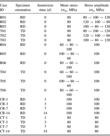
To investigate the ratcheting behaviors under various loading conditions, a series of tests were conducted. The detailed loading conditions are given in Table III.
Loading conditions of ratcheting tests.

E. Microstructure observation
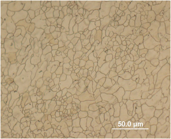
The original specimens were observed with an optical microscope and the microstructure of the rolled ZEK100 sheet was presented in Fig. 1, the average grain size of ZEK100 magnesium alloy is about 20 μm. Before observation, the samples were mounted in epoxy resin, ground with 800, 1000, 1500, 2000, 3000, and 5000 grit SiC paper, followed by electrolytic polishing. The naked corroded surfaces were observed with an SEM after the corrosion products removed.
Optical micrograph of rolled ZEK100 magnesium alloy.

III. RESULTS AND DISCUSSION
A. Tension properties
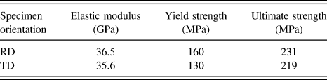
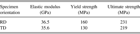
The mechanical properties of the rolled ZEK100 magnesium alloy are shown in Table IV. The tensile YS of the RT specimens is larger than that of TD specimens, and the values are 160 MPa and 130 MPa, respectively. This phenomenon is known as anisotropy, which can in fact be attributed to the texture induced when magnesium alloys are rolled. The basal texture is caused by the reorientation of grains which mainly results from basal slip and tensile twinning during deformation. The dominant deformation mechanisms that are active in magnesium alloys at room temperature are crystallographic slip and deformation twinning including slip on basal (0001), prismatic
 $\left\{ {10\bar 10} \right\}$
systems, as well as twinning on pyramidal
 $\left\{ {10\bar 12} \right\}$
systems (also known as tensile twinning).
Reference Staroselsky and Anand18–Reference Choi, Kim, Lee, Seong, Piao and Wagoner21
And the value of critical resolved shearing stress (CRSS) for the basal slip is lower than that for tensile twinning, which is lower than prismatic slip. During the rolling process, the deformation of rolling direction is larger than that of transverse direction, and several studies
Reference Boba19,Reference Bohlen, Nürnberg, Senn, Letzig and Agnew22
showed that the spread of c-axis of HCP crystal in the rolled ZEK100 is greater toward the transverse direction than the rolling direction, the flow stresses along the transverse direction is lower than that along the rolling direction, which would be an explain to the anisotropy. Hence, the texture may play a critical role in mechanical properties and the ratcheting behaviors of the rolled ZEK100 magnesium alloys.
Tensile properties of the rolled ZEK100 magnesium alloy.
B. Corrosion behavior
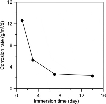
The corrosion rate evolution of ZEK100 sheet in PBS simulated physiological environment is presented in Fig. 2. Obviously, the corrosion rate shows a downtrend with increasing corrosion time. The corrosion starts almost as soon as the specimen is immersed in PBS. The corrosion rate is quite large, even reaches 12.5945 g/(m2 d) in the initial stage of immersion test, then it gradually decreases until stabilizes at the level of about 2.4 g/(m2 d) after immersion for 14 days. Throughout the entire corrosion process, the corrosion rate of ZEK100 in PBS decreases exponentially with increasing immersion time until stabilization. The corrosion rate evolution of various magnesium alloys has been reported in other studies. Reference Fu, Gao, Chen, Gao and Chen8,Reference Xin and Chu15,Reference Witte, Kaese, Haferkamp, Switzer, Meyer-Lindenberg, Wirth and Windhagen23 Although the specific values are different, which may result from the difference between materials, corrosion solution and measurement method, the overall trends are similar.
Corrosion rate of rolled ZEK100 sheet as a function of immersion time in PBS.

The main corrosion forms of magnesium alloy in PBS have been reported to be electrochemical corrosion in other studies. Reference Waizy, Weizbauer, Modrejewski, Witte, Windhagen, Lucas, Kieke, Denkena, Behrens and Meyer-Lindenberg5,Reference Fu, Gao, Chen, Gao and Chen8,Reference Dziuba, Meyer-Lindenberg, Seitz, Waizy, Angrisani and Reifenrath24,Reference Song and Atrens25 The electrochemical corrosion occurs as soon as the specimen is soaked in PBS and the overall corrosion reaction of magnesium alloy is Reference Yang, Yuan, Zhang, Lin, Niu and Ding26,Reference Witte, Hort, Vogt, Cohen, Kainer, Willumeit and Feyerabend27 :
 $${\rm{Mg}} + 2{{\rm{H}}_2}{\rm{O}} = {\rm{Mg}}{({\rm{OH}})_2} + {{\rm{H}}_2} \uparrow \quad .$$
Magnesium alloys corrode very quickly under physiological condition with high concentration of ions, in particular, chloride ions, Reference Zhao, Liu, Song and Atrens28,Reference Ambat, Aung and Zhou29 and the large corrosion rate in the beginning of the immersion tests can be attributed to heterogeneously distribution in ZEK100. The main corrosion product is magnesium hydroxide which will accumulate on the surface of magnesium matrix and form a film to protect the substrate to some degree. With the prolonging of the immersion time, the fresh surface of the matrix disappears gradually. Hence the corrosion rate degrades rapidly in the initial stage. However, the existence of Cl ion can induce the dissolution of the formed film and leave the matrix expose to the solution according to the reaction Reference Song, Atrens, John, Wu and Nairn30 :
 $${\rm{Mg}}{({\rm{OH}})_2} + 2{\rm{C}}{{\rm{l}}^ - } \to {\rm{MgC}}{{\rm{l}}_2} + 2{\rm{O}}{{\rm{H}}^ - }\quad ,$$
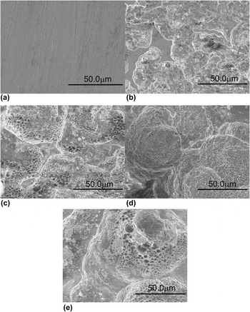
which causes the continuous corrosion. The dissolution-precipitation mechanism controls the dissolution and formation of the magnesium hydroxide film. At the end of the immersion tests, the process achieves a dynamic equilibrium, and it is presented as stable corrosion rate macroscopically. The SEM was used to observe the surface morphologies of ZEK100 sheet immersed in PBS for various durations with corrosion products removed, as shown in Fig. 3, the evolution of the corrosion damage on the surface with the prolonging of the immersion time was illustrated. Obviously, the main corrosion form is the pitting corrosion, which may derive from many factors such as secondary phase distribution and impurities. Reference Fu, Gao, Chen, Gao and Chen8–Reference Chen, Lin and Chen10 There are many visible pits on the naked surface after removing the corrosion products in comparison with the surface of original specimen in Fig. 3(a). After 1 day immersion test, a wide range of pitting corrosion occurs on the surface of ZEK100 plate. The distribution of pits is nonuniformed, some parts of the substrate surface are smooth, while there are irregular corrosion pits on others, which can be seen in Fig. 3(b). With the increase of immersion time, the corrosion pits spread along both longitudinal direction and horizontal direction, as a result, the magnesium alloy matrix suffers serious attack. After 3-day immersion test, there are many small holes on the corrosion pits. It means the anodic reaction occurs in the active sites in these areas, which plays a critical role in the extension of corrosion pits. After being immersed in PBS for 7 days and 14 days, the pitting corrosion is further developed, as is shown in Figs. 3(d) and 3(e), and the corrosion attack is much more serious. The minor pits encounter and coalesce with each other, then bigger pits present, which is demonstrated in Fig. 3(e). And there are a lot of small pits can be seen in the rather big pit. The small pits inside the big one lead to the expansion of corrosion in the longitudinal direction, while the small pits in the marginal area contribute to the development of corrosion in the direction of the width as well as the coalescence with other pits.
SEM morphologies of surface with corrosion products removed under high magnification (magnification: 1000×) for specimens at different immersion durations: (a) original specimen, (b) 1 day, (c) 3 days, (d) 7 days, (e) 14 days.

C. Ratcheting evolution behavior
Typical ratcheting stress–strain curves of uniaxial ratcheting on ZEK100 magnesium alloy (under mean stress of 100 MPa, stress amplitude of 100 MPa and stress rate of 100 MPa/s) are shown in Fig. S1(a). The hysteresis loops are not closed at the beginning of the ratcheting tests, which can explain the ratcheting response of the ZEK100 magnesium alloy. With the increase of cycling number, the unclosed hysteresis loops are closing slowly and almost fully closed in the later period of test, which indicates that the ratcheting strain tends to be stabilizing. From Fig. S1(b), it can be seen that there are two phases in the whole uniaxial strain evolution: rapid accumulation phase (transient), steady phase (steady state). The first phase is transient and characterized by an initial rapid accumulation of ratcheting strain. The second phase is of long duration and relatively constant ratcheting strain accumulation rate. As a matter of fact, the uniaxial strain evolution has been reported in other studies, Reference Ahmadzadeh and Varvani-Farahani13 and the evolution should be divided into three stages: transient, steady state and tertiary. Reference Kang, Gao, Cai and Sun31–Reference Lin, Chen and Chen33 In this case, only 200 cycles are shown in Fig. S1(b), therefore the final failure stage (tertiary) is not presented.
1. Effects of mean stress and stress amplitude
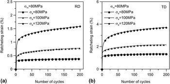
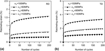
The effects of stress amplitude and mean stress on uniaxial ratcheting strain evolution are shown in Figs. 4 and 5, respectively, it can be seen that they have significant influence on the ratcheting strain accumulation of ZEK100 magnesium alloy. Furthermore, the effects of these two stress parameters on the ratcheting strain evolution conform to the similar trend. Specifically, when other stress parameters are constant, the final ratcheting strain level will increase correspondingly with the increase of stress amplitude or mean stress. Moreover, the similar trend exists in the specimens along two different directions (RD and TD). When the stress amplitudes are 80, 100 and 120 MPa under the constant mean stress of 80 MPa [Fig. 4(a)], the final uniaxial ratcheting strains are 0.385%, 0.773% and 1.596%, respectively. When the mean stress is 60, 80 and 100 MPa under the constant stress amplitudes of 100 MPa [Fig. 5(a)], the final uniaxial ratcheting strains are 0.308%, 0.714% and 1.627%, respectively. To explain these effects of the single stress parameter (σm or σa) on ratcheting behavior, density of dislocations after each asymmetric loading cycle should be taken into account, because the accumulation of ratcheting strain depends on the evolution of dislocation characteristics of material. Reference Kishor, Sahu, Dutta and Mondal34,Reference Ray, Dutta, Sivaprasad and Tarafder35 In this research, the value of σm in every case is positive, which means that σmax is always larger than |σmin| in the loading waveforms. In other words, the density of dislocations at σmax must be larger than that at σmin in each loading cycle. Therefore, the net increase of density of dislocations after each cycle is positive, which causes the accumulation of ratcheting strain. Kishor et al. Reference Kishor, Sahu, Dutta and Mondal34 have reported that the density of dislocations increase with increase in mean stress at constant stress amplitude and increase in stress amplitude at constant mean stress, and it is a reasonable explanation for the phenomenon mentioned above.
Uniaxial ratcheting strain evolution with the constant mean stress of 80 MPa and stress rate of 100 MPa/s: (a) the specimens along the rolling direction (RD) (the first step of R01–R03); (b) the specimens along the transverse direction (TD) (the first step of T01–T03).

Uniaxial ratcheting strain evolution with the constant stress amplitude of 100 MPa and stress rate of 100 MPa/s: (a) the specimens along the rolling direction (RD) (the first step of R04–R06); (b) the specimens along the transverse direction (TD) (the first step of T04–T06).

2. Effects of specimen orientation
Based on the discussion above, the specimen orientation has no effect on the general trends of the variation of the final ratcheting strain of ZEK100 magnesium alloy with constant mean stress and stress amplitude, while the values of the final ratcheting strain do vary for the different specimen orientations (RD and TD).
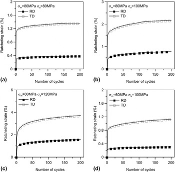
As is shown in Fig. 6, the evolution of the ratcheting strains varies widely in two specimen orientations (RD and TD). The final ratcheting strain of TD specimens is always larger than that of RD specimens.
The ratcheting strain evolution in two different specimen orientations (RD and TD): (a) σm = 80 MPa, σa = 80 MPa; (b) σm = 80 MPa, σa = 100 MPa; (c) σm = 80 MPa, σa = 120 MPa; (d) σm = 60 MPa, σa = 100 MPa.

This phenomenon may be attributed to the different YS in two directions, which was mentioned above. As a matter of fact, the material with larger YS can withstand larger stress before it begins to yield. Hence, the final ratcheting strain will decrease with the increase of YS. As shown in Table IV, the YS of RD specimens is larger than that of TD specimens. Take the specimens R01 and T01 for examples, the final ratcheting strain of T01 is 1.358%, which is larger than that of R01, the value of which is 0.385%.
3. Effects of loading history
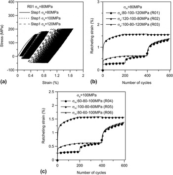
To investigate the effects of loading history on uniaxial ratcheting behaviors, a series of multistep ratcheting tests were carried out, and the loading condition is shown in Table III. Due to the tendency of effects of loading history along the two directions is almost similar, we take the RD specimens for example to illustrate the results. And the relatively experimental results under various multistep loading conditions are shown in Fig. 7.
Effects of loading history on ratcheting behaviors of ZEK100 magnesium alloy: (a) stress–strain curve (R01) of multistep uniaxial ratcheting tests with the constant mean stress and different stress amplitudes; (b) the ratcheting strain evolution of multistep uniaxial ratcheting tests with the constant mean stress and different stress amplitude with different loading sequence (R01, R02, and R03); (c) the ratcheting strain evolution of multistep uniaxial ratcheting tests with the constant stress amplitude and different mean stress with different loading sequence (R04, R05, and R06).

Figure 7(a) shows the stress–strain curve for three-step uniaxial loading of specimen R01 under a constant mean stress of 80 MPa with varied stress amplitude, which were changed from 80 MPa to 100 MPa and 120 MPa step by step, i.e., the loading sequence of stress amplitude is low-high-high. Each loading step includes 200 cycles.
The ratcheting strain evolution under constant mean stress and different stress amplitude with different loading sequences (R01, R02, and R03) is shown in Fig. 7(b), while Fig. 7(c) shows the results under constant stress amplitude and different mean stress with different loading sequences (R04, R05, and R06). It can be seen that prior stress amplitude and mean stress have significant effects on the ratcheting behavior of ZEK100 magnesium alloy. The increase of the stress amplitude (R01) and mean stress (R04) causes the continuous increase of ratcheting strain. Nevertheless, when the loading sequence is changed, the ratcheting strain evolution changes accordingly. Comparing the ratcheting strain evolution curves of the first two steps of specimens R02 and R03, the stress amplitude decreases from 120 MPa to 100 MPa (or from 100 MPa to 80 MPa), the ratcheting strain remains almost constant in subsequent cycles, in other words, the ratcheting strain rate is almost zero. The similar phenomenon occurs in the tests of specimens R05 and R06, as is shown in Fig. 7(c). When the mean stress decreases from 100 MPa to 80 MPa (or from 80 MPa to 60 MPa), the ratcheting strain remain almost constant in subsequent cycles as well. Based on the analysis above, it is reasonable to assume that previous stress-controlled cycling with higher mean stress or stress amplitude will restrain the ratcheting strain accumulation in subsequent cycling with lower mean stress or stress amplitude. These phenomena can be attributed to the enhancement of material deforming resistance, which results from the previous stress-controlled cycling with higher mean stress or stress amplitude. Comparing the ratcheting strain curves of specimens R01 and R02, it is hardly difficult to find that the loading sequence of previous cycling with lower stress amplitude have no significant effect on the ratcheting strain accumulation in subsequent cycling with higher stress amplitude, and the similar tendency is also found in specimens R04 and R05.
4. Effects of precorroded duration
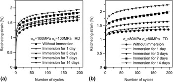
A series of uniaxial ratcheting tests were performed on specimens with different immersion durations to investigate the influence of precorroded duration on ratcheting strain of ZEK100 material. The specific loading conditions are shown in Table III. The typical ratcheting strain evolution of precorroded specimens under the same loading condition is shown in Fig. 8. By comparing the ratcheting strain evolution of specimens with various precorrosion durations, the effects of precorrosion time are conspicuous. With the increase of precorroded time, the accumulation of ratcheting strain is accelerated continuously. In fact, the fatigue life will decrease accordingly due to the reducing of the second stage, Reference Yuan, Yu, Gao and Gao36 which is not shown in the curves because of the limited loading cycles. Other researches Reference Zhao, Gao, Gao, Yuan and Chen7,Reference Fu, Gao, Chen, Gao and Chen8 have reported that corrosion environment can deteriorate the mechanical properties, and the yield stress will decrease with increase in the immersion time, which results in a larger plastic strain. The actual stress that specimens withstand after a certain precorrosion duration is higher than the nominal stress due to the effects of corrosion defects, including notches, pits, and filaments. The defects may affect the mechanical properties of the material by impairing the loading capacity and causing stress concentration. Thus, the ratcheting strain level will increase with increase in the precorroded duration.
Ratcheting strain evolution of precorroded specimens with various immersion durations as well as original ones under stress conditions of (a) σm = 100 MPa, σa = 100 MPa, RD specimens; (b) σm = 80 MPa, σa = 80 MPa, TD specimens.

IV. CONCLUSION
The ratcheting behaviors of ZEK100 magnesium alloys have been investigated. Tensile tests were conducted to obtain the mechanical properties of material. Effects of serval factors, including mean stress, stress amplitude, specimen orientations, loading history, and precorroded duration, were illustrated by comparative analysis. The mean stress, stress amplitude, and loading history have significant effects on the uniaxial ratcheting strain evolution of ZEK100 magnesium alloy. The high levels of mean stress and stress amplitude should be avoided in the application. And the loading history with higher mean stress or stress amplitude will be beneficial for the subsequent stress cycles. The rolled ZEK100 sheet exhibits anisotropy behavior, which should not be a phenomenon to be ignored in the practical application. In addition, the ratcheting strain tends to increase after certain degree degradation in PBS simulated environment.
Supplementary Material
To view supplementary material for this article, please visit https://doi.org/10.1557/jmr.2017.104.
ACKNOWLEDGMENTS
The project was supported by the National Natural Science Foundation of China (Nos. 51571150, 11572222) and Tianjin Natural Science Foundation (Nos. 14JCYBJC16900, 16JCYBJC28400).