
I. INTRODUCTION
Oxide dispersion strengthened (ODS) steels are the promising candidate structural materials for future fusion or enhanced fission reactors. These steels are currently under investigations in comprehensive research programs worldwide. Investigations on ferritic and ferritic–martensitic ODS versions already revealed improved mechanical properties at elevated temperatures.Reference Lindau, Möslang, Schirra, Schlossmacher and Klimenkov1–Reference Chauhan, Hoffmann, Litvinov and Aktaa5 Further improvements are also shown by introducing oxide particles in austenite,Reference Xu, Zhou, Li and He6 a phase with superior strength, creep, corrosion, and oxidation resistance in comparison with ferrite.
ODS steels are generally produced via powder metallurgy that includes mechanical alloying (MA). MA enables homogeneous distribution of oxide particles throughout the matrix.Reference Suryanarayana7 However, the production process of austenitic ODS steels is more difficult in comparison to the ferritic versions. Because of its higher ductility, austenite powder during milling adheres to the wall of the milling container and to the milling media, which decreases the production yield and alternates the chemical composition.Reference Balázsi, Gillemot, Horváth, Wéber, Balázsi, Sahin, Onüralp and Horváth8 Recently, Gräning et al. developed a two-step MA process allowing them to fabricate large batches with sufficient yield.Reference Gräning, Rieth, Hoffmann and Möslang9 These batches (namely, MS VI and MS VIII: MS stands for milling study) were produced using ZrO2 milling balls which led to an increased production yield (75–85%).Reference Gräning, Rieth, Hoffmann and Möslang9 Moreover, the abrasion of ZrO2 balls during milling was conceptualized as an approach to facilitate the formation of nanosized precipitates.Reference Gräning, Rieth, Hoffmann and Möslang9 However, despite the sequestering of Zr in nanosized precipitates, the number of big shards of ZrO2 ruined the mechanical properties, especially the ductility and fatigue lifetime.Reference Gräning, Rieth, Hoffmann and Möslang9,Reference Straßberger, Chauhan, Gräning, Czink and Aktaa10 Since not only coarse (several hundreds of μm) ZrO2 pieces were found on the fracture surface of the tensile test samplesReference Gräning, Rieth, Hoffmann and Möslang9 but also their negative contribution to a lower cyclic life was observed during fatigue tests.Reference Straßberger, Chauhan, Gräning, Czink and Aktaa10 Therefore, to optimize/improve the material, the subsequent batches (one of them, designated herein as MS XVI, is studied as a part of the present framework) were produced using 100Cr6 steel balls. Furthermore, the production yield was increased to 100% by using nitrogen as a process control agent (PCA) during the milling process (described below). This mitigated the adhesion of the powder particles inside the attritor ball mill and resulted in a finer and homogeneous distribution of all elements.Reference Gräning11
The basic monotonic behavior of austenitic ODS steels were studied by several authors, e.g., see Refs. Reference Xu, Zhou, Li and He6 and Reference Miao, Mo, Zhou, Liu, Lan, Zhang, Miller, Powers, Mei, Park, Almer and Stubbins12. It has been shown that these ODS steels exhibit remarkable tensile and creep strength in comparison to their conventional non-ODS counterparts due to the presence of the nano-oxide particles which act as barriers for dislocation motion and grain boundary migration. Similar monotonic tensile results were observed for all our ODS variants (MS VI, MS VIII, and MS XVI) which were reported separately, see Refs. Reference Gräning, Rieth, Hoffmann and Möslang9 and Reference Gräning11. Briefly, out of these versions, MS XVI offers highest yield strength and comparable elongation to failure at room temperature.Reference Gräning11 At elevated temperatures, MS XVI exhibits both superior strength and total elongation-to-failure. While its highest strength was attributed to its highest yttrium content (∼174% higher) which eventually resulted in a formation of higher density of impenetrable nano-oxides, its superior ductility is due to its larger grain size and optimized inclusion free matrix.Reference Gräning11 However, for application, high-temperature low-cycle fatigue (LCF) behavior of these steels is of decisive importance. The knowledge of the LCF behavior of austenitic ODS steels is very scarce and only one study on the two previous versions, namely MS VI and MS VIII, was reported by the authors recently.Reference Straßberger, Chauhan, Gräning, Czink and Aktaa10 This study showed their superior high-temperature fatigue resistance in comparison to their non-ODS counterpart. However, as mentioned above, the presence of the large Zr-enriched inclusions in the MS VI and MS VIII negatively impacted the fatigue lifetime, and hence, resulting in a broad scatter.Reference Straßberger, Chauhan, Gräning, Czink and Aktaa10 The present study is performed to investigate the LCF behavior of their newly optimized version (MS XVI) which is correlated with microstructural evolution after cyclic straining.
II. MATERIALS AND METHODS
The investigated austenitic ODS steel (MS XVI) based on the commercial 316L(N) stainless steels (SSs) was produced by applying a two-step milling process in a ZOZ Simoloyer CM01 mill (ZOZ GmbH, Wenden, Germany), described elsewhere.Reference Gräning, Rieth, Hoffmann and Möslang9 The handling of the powders was executed under argon atmosphere in a glove box. The milling was performed using 100Cr6 milling balls for both milling steps. During milling, the milling chamber was water-cooled and nitrogen was used during second milling step as a PCA to support the embrittlement of the powder particles and to enhance the powder production yield. Table I features the chemical composition of the added powders before milling was conducted. The chemical composition of the powder after MA, the milling time, and the powder production yield are listed in Table II. It is important to note that in comparison to previously reported MS VI (60 h) and MS VIII (70 h),Reference Gräning, Rieth, Hoffmann and Möslang9 MS XVI powder was milled for shorter total duration, i.e., 35 h [as this milling time was sufficient to distribute oxide forming species (e.g. yttrium) into solid solution homogeneouslyReference Gräning11,Reference Deschamps, de Geuser, Malaplate and Sornin13 ]. After MA, the powder was sealed in a soft mild-steel can and degassed at around 500 °C for 3 h. The can was then hot extruded into a rod at around 1100 °C at the Strangpresszentrum Berlin, Germany. A degree of deformation of around −1.6 was applied. No further heat treatment was carried out. It is noteworthy that in comparison to previously reported MS VI and MS VIII,Reference Gräning, Rieth, Hoffmann and Möslang9 MS XVI possesses almost similar composition however having much higher yttrium content (∼174% higher).
Actual chemical composition of used powders in wt% before milling.

Chemical composition of the powder after milling, milling time, and production yield.

Due to the limited quantity of the material, miniaturized specimen geometry with a gauge diameter of 2 mm and a gauge length of 7.6 mm was used at an overall length of 27 mm. To avoid the influence of surface quality on cyclic lifetime, specimens were axially polished. The specimens’ average surface roughness was ∼0.26 µm. All specimens were machined parallel to the extrusion direction of the rod. For LCF testing, a computer-controlled MTS 810 servo hydraulic testing machine (with MTS flex test TM 40 controller (MTS Systems GmbH, Berlin, Germany)), equipped with a radiative furnace and a high-temperature extensometer (having a gauge length of 7 mm), was used. The axial strain-controlled fatigue tests were conducted with the nominal strain rate of 10−3 s−1 and with a fully-reversed triangular waveform (R = −1) in air at 650 °C under three different strain amplitudes (±0.4%, ±0.5%, and ±0.7%). The temperature was controlled to within ±2 °C with a type S Pt–Pt10Rh thermocouple attached to the bottom shoulder of the specimens. Unless otherwise indicated, all stresses reported here correspond to the true stresses.
Microstructural characterization was carried out in both as-received as well as deformed state by transmission electron microscopy (TEM). The samples from the deformed state were prepared by cutting longitudinal platelets using a Well 3242 diamond wire saw (Well Diamantdrahtsagen GmbH, Mannheim, Germany) from the gauge section of the tested specimens. One or two discs were punched out from these longitudinal platelets that were grinded to a thickness of ∼95 µm. The discs were then thinned to electron transparency electrochemically using a Tenupol 5 Jet polisher (Struers GmbH, Willich, Germany). As an electrolyte, a mixture of sulfuric acid (20%) and absolute methanol (80%) was used at 23 °C, 10 V, and a flow rate of 42 (full scale 50). Finally, the electropolished TEM samples were ion milled at 0.1 keV for 15 min to obtain a clean surface. The TEM study was performed with a FEI TECNAI-20F (200 kV) (Thermo Fischer Scientific, Hillsboro, Oregon) TEM equipped with the high-angle annular dark-field (HAADF) detector for scanning TEM (STEM). The elemental analysis was performed using energy dispersive X-ray spectroscopy.
III. RESULTS AND DISCUSSION
A. LCF response
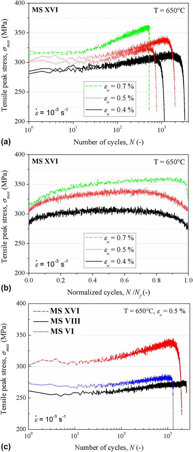
The cyclic stress response curves of MS XVI at 650 °C under three different strain amplitudes are shown in Figs. 1(a) and 1(b). In general, the total cyclic life could be subdivided into four distinct stages. In first stage, the cyclic stress response is almost stable for the first ten cycles [Fig. 1(a)]. Thereafter, in second stage, the material undergoes cyclic hardening where peak stresses increase gradually (30–55 MPa) until they reach a maximum [Figs. 1(a) and 1(b)]. This stage represents the most fraction of the cyclic life (up to ∼0.6N f) depending on the loading amplitude. Here, the rate (to achieve maximum) and the amount of cyclic hardening increases with an increase in applied strain amplitude. Post-hardening, stress amplitudes are stable during the third stage and occupy a minor fraction of the cyclic life (up to ∼0.2N f), as visible in Fig. 1(b). Finally, governed by the fatigue crack initiation and its propagation, peak stresses reduce gradually followed by a precipitous drop until failure.
Cyclic stress response curves [curves of tensile peak stress versus logarithmic number of cycles (a) and versus normalized cycles (b)] of MS XVI at 650 °C under three different strain amplitudes. (c) Comparison of the cyclic stress response curve of MS XVI with those of previously reported MS VI and MS VIII.

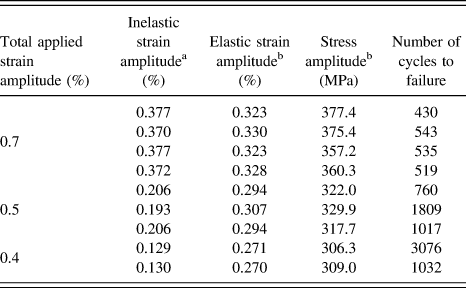
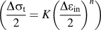
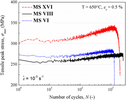
Figure 1(c) features the comparison of cyclic stress response of MS XVI with previously reported versions MS VI and MS VIII, see Ref. Reference Straßberger, Chauhan, Gräning, Czink and Aktaa10. It is evident that though MS XVI exhibits a similar cyclic stress response [Fig. 1(c)], it clearly offers highest cyclic strength and comparable cyclic life, which is quite remarkable. In addition to this, MS XVI undergoes a relatively higher second stage hardening than that observed for MS VI and MS VIII [Fig. 1(c)]. This behavior is also realized for other tested strain amplitudes (not shown here). Hence, from here, it can be concluded that MS XVI offers superior cyclic properties in comparison to previously reported MS VI and MS VIII which themselves showed better fatigue resistance in respect of their non-ODS counterpart.Reference Straßberger, Chauhan, Gräning, Czink and Aktaa10 The main LCF test results of MS XVI are summarized in Table III while those of MS VI and MS VIII can be found in Ref. Reference Straßberger, Chauhan, Gräning, Czink and Aktaa10. The values of the well-known LCF parameters obtained by fitting test data to the corresponding LCF relationsReference Ramberg and Osgood14–Reference Manson16 (see Fig. 2) are listed in Table IV.
Summary of the LCF tests on MS XVI austenitic ODS steel.

a Measured half-width of the hysteresis loop at zero stress at half-life.
b Measured at half-life.
Bilogarithmic plots of the (a) stress amplitude  $\left( {{{\Delta {\sigma _{\rm{t}}}} \over 2}} \right)$ versus inelastic strain amplitude
 $\left( {{{\Delta {\varepsilon _{{\rm{in}}}}} \over 2}} \right)$ fitted linearly with cyclic hardening relationReference Ramberg and Osgood14 and (b) inelastic strain amplitude
 $\left( {{{\Delta {\varepsilon _{{\rm{in}}}}} \over 2}} \right)$ versus number of reversals to failure (2N f) fitted linearly with the Coffin–Manson relation.Reference Coffin15,Reference Manson16

Values of the LCF parameters obtained by fitting test data measured at half-life to the corresponding mentioned relations.

B. Microstructural observations
To understand deformation mechanisms, microstructures were characterized before and after cyclic straining.
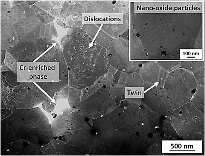
The representative as-received/undeformed state microstructure, observed via TEM in the HAADF-STEM mode, is shown in Fig. 3. This mode shows contrast due to different chemical compositions (Z-contrast based on atomic number), crystallographic orientation, and dislocation density within the grains. As shown in Fig. 3, MS XVI in the as-received state manifests almost equiaxed grains which have a size distribution varying from 0.1 to 2 µm with dominance below 1 µm. In addition, some grains exhibit typical crystallographic defects such as dislocations, stacking faults, and twins, while most grains are almost defect-free. The misorientation analysis via electron backscattered diffraction (not shown here) revealed that the fractions of high-angle boundaries (>15°) and low-angle boundaries (2–15°) are 73% and 27%, respectively.Reference Gräning11 A small fraction of boundaries are the Σ3 twinning boundaries. Furthermore, various nanofeatures are also observed embedded in the matrix, which are planned to be reported in detail separately. Nevertheless, briefly, as shown in Fig. 3, some grain boundaries are decorated with a bright contrast Cr-enriched phase. Here, it is important to mention that this phase could not only form during MA due to the combination of chromium with carbon and oxygen to reduce the overall Gibbs formation energy but can also be an aftermath of segregation amid extrusion.Reference Gräning11 Besides, the majority is of the different dark-contrast nano-oxide particles, identified as Y2O3, Y2Ti2O5, Y2Ti2O7, and Y–Ti–Cr–O, which are distributed in both trans- as well as intergranular regions. These nanoparticles have a size distribution ranging from 1 to 70 nm with most exhibiting a diameter below 5 nm.
HAADF-STEM micrograph revealing MS XVI microstructure from the as-received state.

After cycling, the overall microstructure appears stable without any modifications in grain shape and size. This can be attributed to the presence of the intergranular obstacles which successfully pinned grain boundaries from migration (see the inset in Fig. 3). In addition, twinning and stacking fault fractions in general seem unchanged, as they are still perceived in only few grains. This is in accordance with LCF investigations on conventional austenitic 316L SS,Reference Srinivasan17 where also no deformation-induced twinning was reported. In general, deformation-induced twinning is considered as a stress-controlled process with a critical shear stress associated with it.Reference Byun18 Therefore, nucleation of twins can only take place if the externally applied stress is higher than the critical shear stress for twinning (which depends on the stacking fault energy, crystallographic orientation, grain size, strain rate, and temperature), otherwise slip mechanism will dominate.Reference Byun18–Reference Han, Cheng, Li, Wu and Zhang20 Indeed, after cyclic straining, the main difference was observed in respect of the dislocation density.
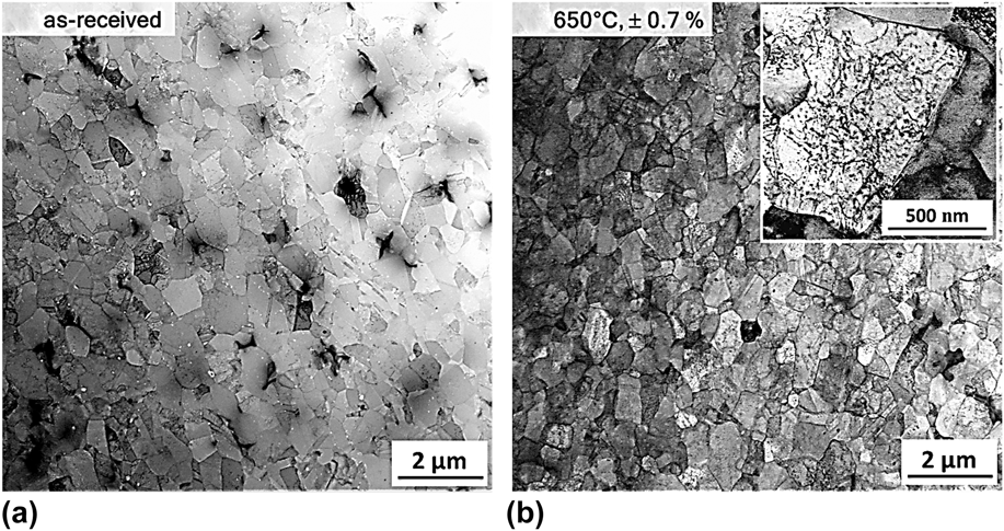
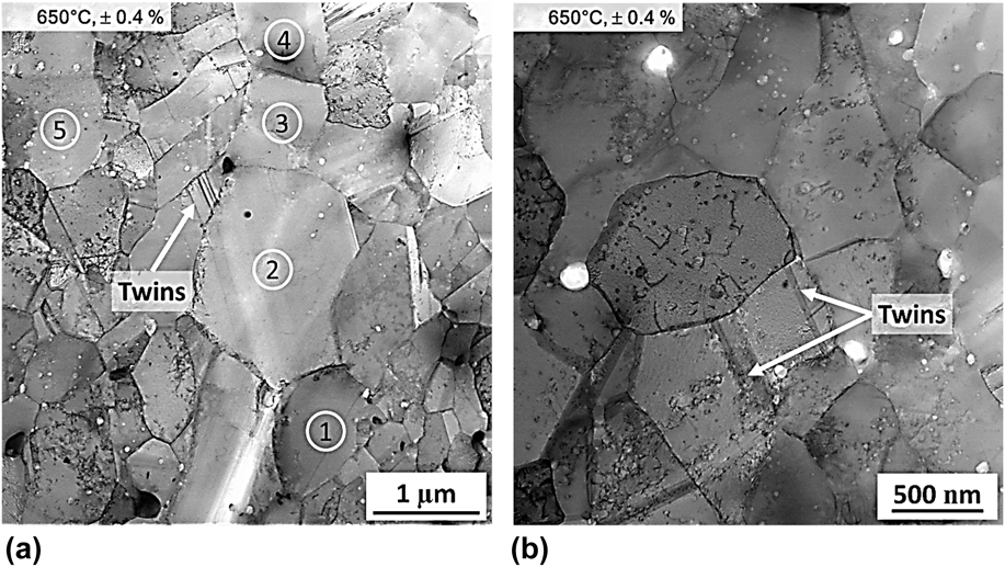
Figure 4 presents the comparison of the microstructure before and after cyclic straining at 650 °C under higher strain amplitude (±0.7%) in the inverted contrast HAADF-STEM mode. It is evident that in the as-received state [Fig. 4(a)], most grains appear clean with light contrast due to the low dislocation density. Whereas, after cycling [Fig. 4(b)], majority of grains manifest an overall homogeneous dark contrast due to high dislocation density (see the inset). Unfortunately, the quantitative dislocation densities could not be estimated due to uncertainty in the determined TEM sample thickness. However, though qualitative, the overall dislocation density is certainly increased, in comparison to that of the undeformed state. Hence, it can be concluded that the second stage hardening in MS XVI is due to the overall increment of the dislocation density. Moreover, as for hardening, the dislocation density is also a function of loading amplitude which increases with its magnitude. For example, apart from the usual deformed grains at lower strain amplitude (±0.4%), decent numbers of grains are still nearly free of dislocations [see numbered grains in Fig. 5(a)]. This indicates a comparatively inhomogeneous deformation. The dislocation-free regions/grains apparently lower the overall dislocation density and therefore, as a consequence, lower associated cyclic hardening at lower strain amplitudes. This is also related to the comparatively lower-induced inelastic strain at lower applied strain amplitude than at higher ones, see Table III.
Inverted contrast HAADF-STEM micrographs reveal microstructures (a) before (as-received state) and (b) after cyclic straining at 650 °C under ±0.7% strain amplitude. A relatively darker contrast grain in (b) is due to the presence of high dislocation density.

Inverted contrast HAADF-STEM micrographs revealing microstructures after cyclic straining at 650 °C under ±0.4% strain amplitude. (a) Numbered grains (1, 2, 3, 4, and 5) that are nearly free of dislocations and (b) grains at higher magnification with high density of short dislocations pinned at various nanoparticles.

During cyclic deformation, microstructural modifications transpire to achieve stable low energy configurations. Here, the modification rate and amount precisely depend upon the testing conditions such as deformation rate (strain rate), its extent (amplitude), and temperature. However, before the steady state is attained, the competition between dislocation generation/multiplication and their annihilation/storage (via dislocation–dislocation annihilation and dislocation–grain boundary interaction) occurs simultaneously. And the dominance of one mechanism over the other defines the evolution of dislocation density, and hence, the overall material behavior. For example, in case of MS XVI, a material with low initial dislocation density, the increment in dislocation density upon cycling suggests that the rate of dislocation generation/multiplication is obviously far greater than that of their annihilation/storage. By contrast, in ferritic–martensitic steels, which are known to undergo cyclic softening due to the overall reduction in dislocation density,Reference Chauhan, Hoffmann, Litvinov and Aktaa5 the rate of dislocation annihilation/storage is significantly larger than that of their generation/multiplication. Nevertheless, once the steady state is reached, the rate of dislocation generation/multiplication as well as their annihilation/storage is balanced. And hence, a stable dislocation density (which is apparently higher than in the undeformed state for MS XVI) leads to a stable cyclic response with constant peak stress (third stage).
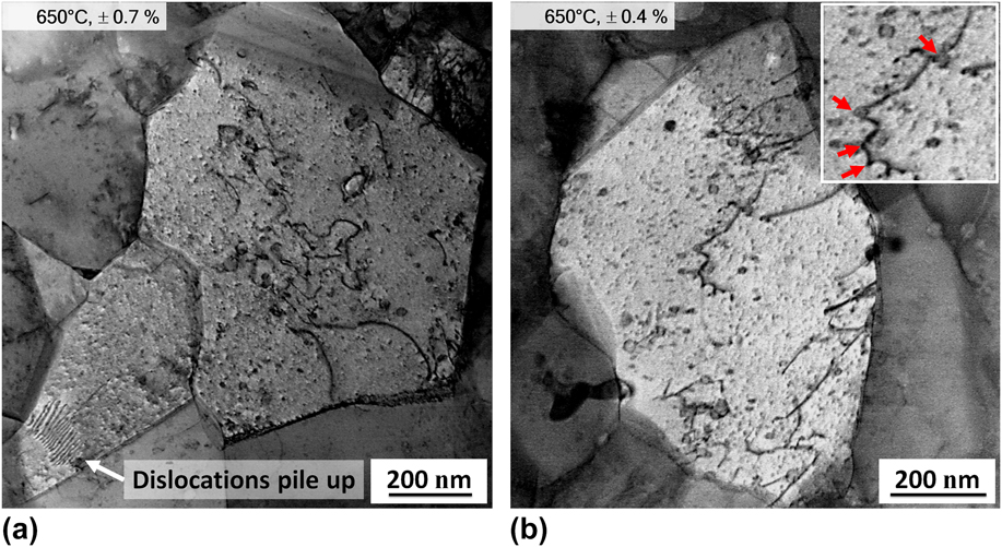
In respect of the dislocation structures, mostly intragranular dislocation activity is observed along with the occasional dislocation pile up (Fig. 6). However, no noticeable three-dimensional (3D) dislocation arrangements such as the cells, ladder, vein, labyrinth, and persistent slip bands were identified. These typical 3D dislocation structures are commonly observed upon cycling conventional non-ODS austenitic steels, e.g., 316L SSReference Srinivasan17,Reference Gerland and Violan21 which are associated with the formation of extrusions and intrusions where fatigue cracks nucleate.Reference Man, Obrtlík and Polák22 Their absence in MS XVI could be due to (i) embedded nano-oxide particles and/or (ii) its ultrafine grains (mostly below 1 µm).
Inverted contrast HAADF-STEM micrographs revealing dislocation structure after cyclic straining at 650 °C under ±0.7% (a) and ±0.4% (b) strain amplitudes. Clearly, high intragranular dislocation activity along with dislocation pile up is apparent from (a). The inset from (b) shows dislocation pinned at various nanoparticle–matrix interfaces.

Concerning oxide particles, in almost all grains, individual dislocations (short as well as long) appear pinned at the nanoparticle–matrix interfaces and under the effect of shear stresses, most of them are bowed out (Fig. 6). This indicates an attractive particle–dislocation interaction since pinning is realized on both arrival as well as departure side of the nanoparticles.Reference Chauhan, Hoffmann, Litvinov and Aktaa5 Therefore, there exists a threshold stress to detach dislocation out of this pinning, which must be overcome for the dislocation to glide; and therefore, plastic deformation to occur.Reference Nardone and Tien23–Reference Reppich25 This results in a retarded dislocation’s mobility, and hence, inhibiting strain localization by prohibiting 3D dislocation structure formation. Moreover, dislocation pinning provides a consequent strengthening which give ODS steels their superior monotonic as well as cyclic strength over non-ODS counterparts, e.g., see Refs. Reference Chauhan, Walter and Aktaa4, Reference Xu, Zhou, Li and He6, and Reference Straßberger, Chauhan, Gräning, Czink and Aktaa10. Furthermore, in comparison to the previous versions (MS VI and MS VIII), MS XVI higher cyclic strength and comparable cyclic life [Fig. 1(c)] can be attributed to its higher yttrium fraction (∼174%), which eventually resulted in a formation of higher density of impenetrable nano-oxides. This higher density of nano-oxide particles leads to a higher percentage of dislocation pinning which not only shows up in terms of their higher strength but also due to their higher restricted movement less number of dislocations reach the specimen’s surface for annihilation which retards the onset of damage.
However, Thiele et al. also pointed out that some minimum volume (∼1 µm in terms of grain size) is required for the creation of persistent slip bands or 3D dislocation structures.Reference Thiele, Holste and Klemm26 And since MS XVI is designed to have a submicron sized matrix, to achieve additional superimposed grain size strengthening without adversely affecting ductility and toughness,Reference Chauhan, Bergner, Etienne, Aktaa, de Carlan, Heintze, Litvinov, Hernandez-Mayoral, Oñorbe, Radiguet and Ulbricht27 the formation of above-mentioned 3D dislocation structures is also suppressed.Reference Chauhan, Litvinov and Aktaa28 On the contrary, ODS steels with particles deficient large grains and/or large volumes with similar orientations manifest 3D dislocation structures.Reference Chauhan, Litvinov and Aktaa28,Reference Kubena and Kruml29 Hence, due to both homogeneous particle distribution and ultrafine grains, the onset and progress of damage in MS XVI will also be constrained since no 3D dislocation structures evolve which are associated with the formation of extrusions and intrusions.Reference Man, Obrtlík and Polák22
Besides, in comparison to the previously reported MS VI and MS VIII, MS XVI exhibits higher second stage hardening [Fig. 1(c)]. This can be attributed to its comparatively larger grain size. In terms of number fraction, the MS XVI average grain size (∼318 nm) is 172% and 189%, higher than that of the MS VI (∼117 nm) and MS VIII (∼110 nm), respectively.Reference Gräning, Rieth, Hoffmann and Möslang9 Large grains are known to have an excellent dislocation storage capacity and significant work hardening ability.Reference Wang, Chen, Zhou and Ma30 This significant work hardening ability of the large grains not only assists in minimizing the stored energy but also accumulates inelastic strain during cyclic straining.Reference Chauhan, Litvinov and Aktaa28 Hence, due to its comparatively higher average grain size, MS XVI exhibits higher cyclic hardening. At first glance, MS XVI higher average grain size appears counterintuitive with its comparatively higher density of impenetrable nano-oxides. Since higher density of dispersed nano-oxide particles are usually known to hinder grain growth more effectively.Reference Humphreys and Hatherly31 However, it is important to note that in comparison to previously reported MS VI (60 h) and MS VIII (70 h),Reference Gräning, Rieth, Hoffmann and Möslang9 MS XVI powder was milled for shorter duration, i.e., 35 h [as this milling time was sufficient to distribute oxide forming species (e.g. yttrium) into solid solution homogeneouslyReference Gräning11,Reference Deschamps, de Geuser, Malaplate and Sornin13 ]. As a consequence, MS XVI powder underwent a comparatively lower degree of deformation which is manifested in terms of lower density of crystal defects such as dislocations and grain boundaries than MS VI and MS VIII powder. These crystal defects are known to be the nucleation sites for new grains during recrystallization.Reference Humphreys and Hatherly31 Therefore, due to its lower crystal defect density, MS XVI powder should have comparatively less newly nucleated grains that have grown during recrystallization amid hot extrusion, which is vice versa for MS VI and MS VIII. Furthermore, precipitation and coarsening of the nanometer-scale oxides also occur during hot extrusion.Reference Deschamps, de Geuser, Malaplate and Sornin13 Hence, this nano-oxide precipitation and the grain growth during extrusion are two competing processes (timewise). And if grain growth occurs before the formation of precipitates, these grains can grow freely until the precipitation has formed large enough precipitates to exert a pinning force, which is larger than the driving force for grain growth. It appears that the grain growth was relatively faster in the MS XVI than the precipitates formation, due to the shorter milling duration.
IV. CONCLUSIONS
The fully reversed strain-controlled LCF tests conducted on an improved austenitic ODS steel in air at 650 °C under three different strain amplitudes led to following conclusions:
(1) The measured cyclic stress response showed four distinct stages which include short initial stable cyclic response followed by a prolonged hardening with subsequent short saturation and finally crack initiation and growth stage.
(2) The rate of hardening and the duration of the stages is a function of applied strain amplitude.
(3) After cycling, the overall microstructure appears stable without any modifications in grain shape and size. This is due to the presence of the intergranular obstacles which successfully pinned grain boundaries from migration. In addition, original twinning and stacking fault fractions seem unchanged. However, cyclic hardening is an aftermath of dislocation multiplication whose rate is a function of applied strain amplitude.
(4) In MS XVI, oxide particles as well as fine grains inhibit strain localization by restricting 3D dislocation structure formation which are associated with the development of extrusions and intrusions and are readily observed in conventional austenitic non-ODS steels. This finally bestowed ODS steels their higher fatigue resistance in comparison to their non-ODS counterparts.
(5) In comparison to previously reported ODS versions,Reference Straßberger, Chauhan, Gräning, Czink and Aktaa10 MS XVI offers highest cyclic strength, relatively higher cyclic hardening and comparable cyclic life. While higher cyclic strength and comparable cyclic life is attributed to its higher yttrium fraction, higher cyclic hardening is associated with its comparatively larger average grain size.