I. INTRODUCTION
Current challenges in large scale off-shore wind turbine condition monitoring (CM) and structural health monitoring (SHM) systems require robust wireless sensors that can provide operational information for long duration on rotating and shielded components continuously in a challenging environment. CM of rotary components in a wind turbine system is critical for health assessment of the asset [Reference Segovia Garcia, Revie and Quail1], minimizing down time and reducing huge maintenance and logistics impact [Reference Ciang, Lee and Bang2]. Having in mind of the long-term usability of wireless sensors in the off-shore wind turbine CM systems, this paper highlights the possibility of utilizing wireless power transfer (WPT) technologies to power wireless sensor nodes on rotating machines [Reference Xia and Quail3].
Sensor nodes on rotating machines are typically deployed in two ways, namely wired and wireless connection. Wired connection, such as mechanical slip ring, ensures the reliable power supply and data exchanges between sensors and data acquisition system, but challenges are wear, limitation on the rotating speed, spark hazard, and difficulty in installation [Reference Ludois, Reed and Hanson4]. For applications in rotating machines, such as wind turbine drivetrains and blades, wireless sensor offers the simplified installation and increased robustness [Reference Lynch and Loh5].
The long-term availability of wireless sensors is mainly constrained by power supply, despite the failure of sensor function or wireless communication link [Reference Ciang, Lee and Bang2]. Along with the continuous improvement of sensor design, further research is invited for the reliable power supply to wireless sensor node with a high speed communication link like WiFi [Reference Jin-Shyan, Yu-Wei and Chung-Chou6]. The solutions can be divided in two categories, i.e. methods to extend battery service time and a variety of energy harvesting technologies. Adopting ultra-low power consuming wireless sensors and a wake-up mechanism, Wendt [Reference Wendt and Reindl7] extends batteries’ service time to several years. Powercast Corporation [8] introduces a new commercial battery aiming at no replacement up to 15 years on wireless sensor node, but it is not cost-effective for massive deployment. The alternate approach is to harvest energy from solar radiation, vibration, thermal gradient, ambient radio frequency or other natural sources [Reference Chalasani and Conrad9]. The energy harvesting technologies have been reviewed and discussed by Gyuhae [Reference Park, Rosing, Todd, Farrar and Hodgkiss10], and it is concluded that the energy captured is either inadequate to independently drive majority of electronic sensors or unaffordable for massive deployment [Reference Chalasani and Conrad9, Reference Arms, Townsend, Churchill, Galbreath and Mundell11]. For example, passive radio-frequency identification (RFID) receiver [Reference Chawla and Dong-Sam12], piezoelectric vibration [Reference Saadon and Sidek13] and thermal gradient [Reference Lu and Yang14] harvester deployed under normal operational temperature, cannot power common sensors continuously for the application of high speed CM. Other higher density natural energy sources, such as solar panels and small scale wind turbines, have the fluctuating output depending on weather conditions [Reference Chalasani and Conrad9].
The rapidly developing WPT technologies, such as electro-magnetic induction charging, magnetic resonant inductive coupling, radio-frequency (RF) radiation, laser beam charging and micro-wave conversion, provide the potential energy sources for wireless sensor networks [Reference Hui, Zhong and Lee15]. Among these approaches, magnetic induction charging is considered relatively mature in the commercial electronics market for a wide range of standard compliant commercial products [Reference Hui, Zhong and Lee15]. The Qi standard [Reference Manivannan and Bharathiraja16], which is defined and certified by the industrial alliance of Wireless Power Consortium (WPC), is promising for the short distance WPT based on tightly-coupled magnetic induction. Another competing standard from the Alliance for Wireless Power (A4WP) targets at the mid-long range WPT using magnetic resonance [Reference Triggs17]. Magnetic resonance is a relatively new wireless charging technology [Reference Kurs, Karalis, Moffatt, Joannopoulos, Fisher and Soljačić18] firstly demonstrated in the WiTricity project. The researchers successfully power a 60 W light bulb from a distance of 2 m [Reference Kurs, Karalis, Moffatt, Joannopoulos, Fisher and Soljačić18, Reference Kesler19]. These WPT solutions can supply a stable and powerful energy source to the sensor nodes on rotating machines.
In this paper, different WPT solutions are compared and magnetic coupling based solutions are experimentally tested to power wireless sensors continuously. Four different configurations of the transmitter and receiver coils are investigated on rotating machines. In order to harvest and store intermittent energy input from a wireless power source, the supercapacitor gathering energy from the intermittent power supply from the receiver coil is validated against a prototype circuit. Moreover, the prototype circuit of multiple receiver coils is built to power wireless sensors on a small wind turbine test rig.
II. TECHNOLOGY SELECTION
A) Comparison of different technologies
Near field non-radiative magnetic coupling is the mainstream approach to achieve WPT, as other approaches including RF radiation, capacitive coupling, laser beam charging, and micro-wave conversion are under development [Reference Shoki20]. Magnetic coupling has been commercially adopted to power a wide range of devices, from low power rating electronics to high power rating electric vehicles; some detailed reviews can be found [Reference Fisher, Farley, Gao, Bai and Tse21, Reference Xie, Shi, Hou and Lou22] for electric vehicles and wireless sensor network. According to the unique requirement of the high reliability but low power rating, commercial-off-the-shelf WPT solutions are preferred for powering wireless sensor networks. Furthermore, the WPT solution should be less sensitive to the angular movement of wireless sensor nodes on rotating machines.
In addition to low frequency magnetic coupling, it is possible to separate signals and energy from RF waves for energy harvesting. Energy harvesting from passive RFID receiver falls into this category [Reference Chawla and Dong-Sam12, Reference Sample, Yeager, Powledge, Mamishev and Smith23]. The wave energy emitted from the transmitter antenna of the base station can be harvested by the receiver antenna. The charging distance can be largely extended to several meters, because common RF emission has a very high frequency like 915 MHz [Reference Bouchouicha24]. However, power transfer efficiency for RF emission is limited, because RF waves decay quickly with distance [Reference Park, Rosing, Todd, Farrar and Hodgkiss10, Reference Arms, Townsend, Churchill, Galbreath and Mundell11]. It is demonstrated that the best output of a typical RF energy harvester is approximately 0.049 W for a 3 W input [Reference Xie, Shi, Hou and Lou25]. Even though the transfer efficiency is low, this method is still suitable for some ultra-low power applications, e.g. some humidity sensors with a power consumption of 0.01 W [Reference Xie, Shi, Hou and Lou25]. The lack of directivity is another cause for the low transfer efficiency; the receiver can only capture a small portion of the total energy. Like the magnetic resonance approach, the potential health hazard of RF radiation to humans remains as a concern for the high energy density at the frequency around 1 GHz [Reference Ahlbom26].
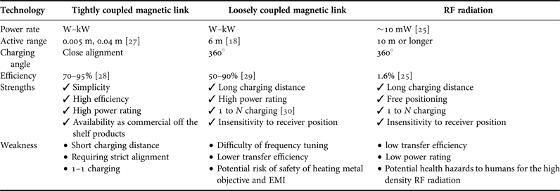
Three potential WPT solutions suitable for powering wireless sensors on rotating machines, are compared in Table I. Magnetic induction has the advantages of higher power rating and less safety concern for the application of wireless sensor charging. In contrast, WPT solutions via magnetic resonance and RF radiation naturally overcome the difficulties for charging sensors in motion, since a flexible receiver positioning and a longer charging distance is allowed. Currently, the technology of magnetic resonance charging is not commercialized as widely as the tight coupling technology for experimental evaluation; a wide range of sensors cannot be powered by the limited power rating transferred by the RF radiation. Microwave or visible light radiation has higher transfer efficiency for fixed direction energy transmission, but the application in mobile devices is limited to line of sight propagation. Therefore, this paper focuses on the solutions based on magnetic coupling.
Comparison of common WPT technologies.

B) Principles of magnetic coupling
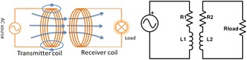
The principle of WPT by magnetic coupling can be explained by the air coil transformer model, as illustrated in Fig. 1. The transmitter (primary) coil and the receiver (secondary) coil form an adjustable contactless transformer. According to the theory of Faraday's Law [Reference Manivannan and Bharathiraja16], the change of the magnetic flux in a coil results in an inductive current. If an alternating current (AC) flows in the transmitter coil, the generated varying magnetic field induces a fluctuating voltage across the receiver coil.
Demonstration of magnetic induction in tightly coupling and equivalent circuit.

For the non-resonant magnetic coupling circuit shown in Fig. 1, power transfer link efficiency η as the ratio of power consumed by the receiver's load to the transmitter's power input, mainly depends on the mutual inductance [Reference Ali, Ahmad and Khan31], magnetic field angular velocity ω, and resistance matching of load and coil resistance R 1, R 2.
 $$\displaystyle{{V_{load}} \over {V_1}} = \displaystyle{{j\omega R_{load} M} \over \matrix{(M^2 - L_1 L_2 )\omega ^2 + (L_1 R_2 + L_1 R_{load} \hfill \cr \quad + L_2 R_1 )j\omega + R_1 (R_{load} + R_2 )^{} \hfill}} \;, $$
 $$\eta = \displaystyle{{R_{load} \omega ^2 M^2} \over {((R_{load} + R_2 )M^2 + R_1 L_2^2 )\omega ^2 + R_1 (R_{load} + R_2 )^2}}. $$
Mutual inductance of the transformer model
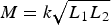 $M = k\sqrt {L_1 L_2} $
depends not only on the coils’ self-inductance L
1 and L
2, but also on the coupling coefficient k, the ratio of magnetic flux though the secondary coil to the total flux generated by the primary coil. In other words, k = 1 means the two coils are perfectly coupled as in the ideal transformer model. If k > 0.5, the two coils are regarded as tightly-coupled, while the two coils are loosely-coupled if k < 0.5. For the transmitter and receiver coils of similar diameter in coaxial alignment, the coupling coefficient k is given by [Reference Matias, Cunha and Martins32],
 $$k = \displaystyle{{\mu _0 N_1^2 A_1^{}} \over {2L_1}} \; \cdot \displaystyle{{r_2^2} \over {\left( {r_1^2 + z^2} \right)^{\textstyle{3 \over 2}}}} \cdot K_{core} (f,d),$$
where A is the coil cross-sectional area, z is the coils separation distance; r is the coil radius; μ 0 is the magnetic permeability of free space, N is in the number of coil turns. In particular, coefficient K core (f, d) takes the effect of a magnetic core inside a coil into account, which depends on d and excitation frequency f. A ferrite core increases the magnetic flux of the coils, moreover it acts as a guide for the magnetic field in order to increase the coupling coefficient between the two coils. Since the coupling coefficient k is significantly influenced by the relative positioning, e.g. the coils distance, lateral misalignment, orientation [Reference Van Schuylenbergh and Puers33], close alignment of the coils is required for a highly efficient power transfer by magnetic induction. For a longer coil separation distance, the non-resonant induction method is less efficient and the majority of the energy is wasted in resistive losses in the primary coil [Reference Matias, Cunha and Martins32].
For transmitter and receiver coils of distinct diameter and non-coaxial configuration, the coupling coefficient k or mutual induction M can be integrated from Neumann equation. Furthermore, a simplified formula is provided for the coils with both axial separation and lateral displacement [Reference Raju, Wu, Chan and Yue34].
 $$\eqalign{M & = \displaystyle{{\mu _0 \pi a^2 b^2} \over {2(a^2 + b^2 + z^2 + x^2 )^{3/2}}} \cr & \quad [1 - \displaystyle{3 \over 2}\delta + \displaystyle{{15} \over {32}}\gamma ^2 \left( {1 - \displaystyle{{21} \over 2}\delta} \right) + \displaystyle{{15} \over {16}}(\alpha ^2 + \beta ^2 )(1 - \displaystyle{7 \over 4}\delta )],} $$
where a is the radius of the first coil, b is the radius of the second coil, z is coaxial separation, x is the lateral displacement. α = 2xa/(a 2 + b 2 + z 2 + x 2), β = 2xb/(a 2 + b 2 + z 2 + x 2), γ = 2ab/(a 2 + b 2 + z 2 + x 2), and δ = x 2/(a 2 + b 2 + z 2 + x 2). The coupling coefficient k drops quickly as the coaxial separation and lateral displacement increase; hence physical proximity of coils is required for high efficient WPT via non-resonant coupling.
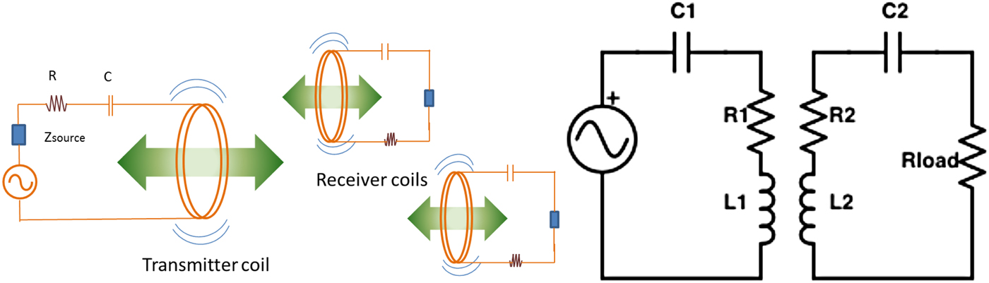
Given a low coupling coefficient k, considerable amount of power can be transmitted via magnetic resonance. When one coil with an alternating current generates electromagnetic field of a certain frequency, other coils or metallic objects in the near field that have the same inherent frequency start to resonate and generate electrical current [Reference Kurs, Karalis, Moffatt, Joannopoulos, Fisher and Soljačić18]. This phenomenon is similar to the mechanical resonance, produced by a tuning fork. Current is generated from the magnetic resonance in the receiver circuit, due to the oscillating magnetic field excited by the transmitter coil. To build a simple resonance charging circuit, the magnetic induction circuit is modified with additional capacitors to form LC resonator [Reference Kesler19], as shown in Fig. 2. The resonating primary circuit only increases the voltage ratio, while resonating secondary circuit can improve both voltage ratio and link efficiency [Reference Ali, Ahmad and Khan31].
Demonstration of magnetic resonance and equivalent circuit.

Besides the coupling coefficient k, the WPT link efficiency η for magnetic resonance depends on the quality factor Q of the transmitter and receiver coils, especially for the high resonance frequencies.
 $$Q = \displaystyle{{2\pi fL} \over R}.$$
Although the self-inductance of a coil L is less sensitive to the excitation frequency f while the equivalent series resistance R increases significantly with f, due to proximity effects, the skin-effect and potentially eddy current losses [Reference Wielandt and Stevens35].
Based on the simplified circuit in Fig. 2, the efficiency of resonant magnetic coupling is given [Reference Kesler19],
 $$\displaystyle{{P_L} \over {P_{g,max}}} = \displaystyle{{4U^2 \displaystyle{{R_g} \over {R_1}} \displaystyle{{R_{Load}} \over {R_2}}} \over {\left( {\left( {1 + \displaystyle{{R_g} \over {R_1}}} \right)\left( {1 + \displaystyle{{R_{Load}} \over {R_2}}} \right) + U^2} \right)^2}}, $$
where P
L
is the power deliverred to the resistive load R
Load
, Pg,max
is the maximum power consumption of the AC power source with a intrinsic resistant R
g
. The maximum possible efficiency depends only on the figure of merit,
 $U = k\sqrt {Q_{Tr} Q_{Rr}} $
.
 $$\eta _{opt} = \displaystyle{{U^2} \over {(1 + \sqrt {1 + U^2} )}}\; {\rm when}\; \displaystyle{{R_1} \over {R_g}} = \displaystyle{{R_{load}} \over {R_2}} = \sqrt {1 + U^2}. $$
Adding resonant capacitor in primary circuit will not improve the efficiency but the voltage ratio between the receiver output and transmitter input, while the matching frequency of both coils can increase the transfer efficiency significantly. The maximum efficiency and maximum power rate cannot be achieved at the same time. The maximum power transfer is based on impedance matching, R Load = R 2 , which does not happen with the optimized efficiency.
Given the low coupling coefficient k for the coils not in close alignment, the high power transfer efficiency relies on the matching of resonant frequency f 0 between the transmitter and the receiver coils,
 $$f_0 = \displaystyle{1 \over {2\pi \sqrt {C_{Tr} L_{Tr}}}} = \displaystyle{1 \over {2\pi \sqrt {C_{Rr} L_{Rr}}}}. $$
The introduction of intermediate coils potentially maintains the power transfer efficiency for a wider frequency range [Reference Kim, Son, Kim and Park29]. In addition, recent research suggests efficiency of WPT also depends on the impedance matching of coils [Reference Beh, Imura, Kato and Hori36]. Resonance circuit is essential to loosely coupled system, but applicable to tightly coupled magnetic link. For tightly coupling, LC resonance can improve the efficiency and maximum power rating. For example, the industrial WPT standard Qi also has a series capacitor to tune the WPT efficiency for lower coupling coefficient from 0.2 to 0.7, and the best results are achieved at a transmitting frequency that is slightly different from the resonant frequency of the Qi receiver. This off-resonant operation reaches the highest amount of power at the best efficiency; this mode is called “inductive”. Therefore, the distinction of induction predominant or resonance predominant solution depends on coupling coefficient and resonance frequency sensitivity.
C) Comparison of tightly and loosely coupling
Both tight coupling and loose coupling have their unique advantages for WPT. Tight coupling can obtain a transfer efficient up to 95% for close alignment, and the power rate reaches several kW. Wireless charging by loose coupling offers flexibility provides the longer charging range and more positional allowance [Reference Hui, Zhong and Lee15]. As shown in Fig. 2, power transfer based on magnetic resonance does not require the transmitter and the receiver in close line-up position; free positioning of the coils is possible within several meters [Reference Kesler19]. However, the efficiency of magnetic resonance is still sensitive to the coils distance and resonance frequency matching. For a strictly-aligned configuration, a high efficiency of 90% can be achieved at 1 m but only 50% at 2 m [Reference Kurs, Karalis, Moffatt, Joannopoulos, Fisher and Soljačić18]. Moreover, the magnetic resonance approach is promising for charging multiple sensors simultaneously for wireless sensor network [Reference Kim, Son, Kim, Kim and Park30].
Tightly coupled wireless chargers, like Qi standard compliant products, have already been commercialized, and can be conveniently adapted to charge wireless sensors in a cost effective manner. The Qi standard [Reference Johns27] is the first industrial standard for wireless charging that defines, standardizes, and certifies the interfacing terminal, switching frequency range, quality of power and the communication protocol for commercial electronics. Due to the tight coupling characteristics, the Qi standard is designed for proximal WPT applications. According to the Qi specification version 1.0, the transmitted power rating is 5 W or less for low power applications and 120 W for medium power applications. In addition, the WPC recently announced that the Qi standard will extend the charging distance from 5 to 40 mm, which will significantly improve the charging performance and flexibility in transmitter and receiver positioning [Reference Manivannan and Bharathiraja16]. Based on the on-demand intelligent charging protocol, a Qi compliant receiver commences a two-way communication before charging. Another standard technology based on tight coupling is defined by Power Matters Alliance (PMA), which has insignificant technical difference for interoperation with WPT. In 2015, the merge of PMA with A4WP creates the new industrial standard AirFuel™. Based on magnetic resonance charging technology, this standard provides the flexibility of positioning, 1 to N charging configuration, and a longer charging range between chargers and power consumers [Reference Kesler19].
For the specific application of WPT to rotating machines, device safety and human exposure should be considered. The ultimate goal of WPT to rotating machine is to power sensor and actuator; hence the introduction of WPT should not affect existent sensing and actuating circuit. For the typical magnetic coupling frequencies, 110 ~ 205 kHz for tightly-coupled and 6.78 MHz [Reference Johns37] for loosely-coupled solution, eddy current heating is considered a hazard if coils are surrounding the metal rotating components. Loose coupling approach is ideal for charging multiple sensors in motion for the applications in rotating machines, but there is a risk of EMI. In addition, human exposure to electromagnetic field is worth of investigation before deployment. However, it is reported that the cell growth rate and cell cycle distribution is not affected with a resonant frequency of 12.5 MHz, while magnetic field at the positions of the cell culture dishes is approximately twice the reference level for occupational exposure by the International Commission on Non-Ionizing Radiation Protection (ICNIRP) guidelines [Reference Mizuno, Miyakoshi and Shinohara38]. Considering the difficulty of shield AC magnetic field and heating effect, this study focuses on tightly coupled approaches, leaving the loosely-coupled solution for future exploration.
D) Heating effect
Dependence on coil-shaft configuration and shaft material, heating effect on proximal object by the transmitter coil is worth of investigation. If the transmitter coil is close to any metal or conductive surface, eddy current heating may elevate the surface temperature dramatically so that the microstructure and mechanical strength is compromised. For low magnetic permeability material like Aluminum and Austenitic stainless steel, the hysteresis loss is low as air core. In case of transmitter coil riding on high magnetic permeability shaft, the heating effect must be evaluated. Both hysteresis loss and eddy current loss depend upon magnetic properties of the materials core, and they are extensively studied in transformer design [Reference Hurley and Wolfle39]. Hysteresis loss per volume in transformer is calculated by Steinmetz formula,
 $$P_h = K_h f(B_{max} )^{1.6}, $$
where, f is the frequency, K h is the hysteresis coefficient and B max is the maximum flux density, the empirical exponent of B max varies from about 1.4–1.8 but is often given as 1.6 for iron. Eddy current loss per volume in transformer is denoted as,
 $$P_e = K_e (fK_f B_{max} )^2, $$
where K e is eddy current constant, K f is form constant. Due to the skin effect at high frequency, the eddy current happens only at a small depth.
Reducing the resonance frequency can reduce the eddy current and hysteresis loss, while the coupling efficiency is less affected according to equation (7). For example, a low frequency WPT is able to deliver 2.967 W power at 180 Hz to an 117.1 Ω resistor over 1 cm distance with 50% overall efficiency [Reference Hao40]. Due to the low operating frequency, RF radiation hazard and tissue absorption are largely avoided for implanted device. On the receiver coil, the reduction of open circuit output voltage V(t) by the decreased frequency can be compensated by the high magnetic permeability of the shaft material enclosed by the transmitter coil. According to equation (11), the high magnetic permeability material serves as magnetic core for transformer that increases the magnetic field intensity within the coil.
 $$V(t) = NA\displaystyle{{d{\rm B}(t)} \over {dt}},$$
where N is the turn of receiver coil, A is the enclosed area and B(t) is the spatial averaged magnetic field intensity of the coil.
III. EXPERIMENTAL EVALUATION OF WIRELESS CHARGING
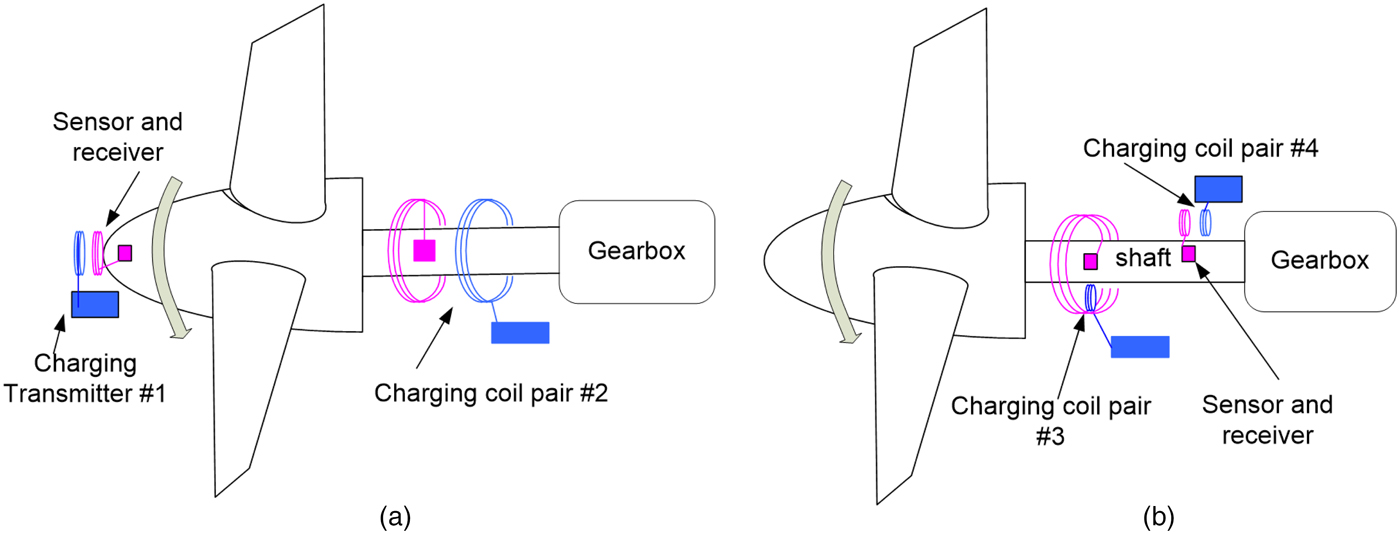
In order to charge wireless sensors on rotating components, a tight but non-contact coupling of transmitter and receiver coils is considered for the magnetic coupling. Figure 3 demonstrates some possible positioning configurations for transmitter and receiver coils. The feasibility of wireless charging by a Qi compliant charging kit (charging coil pair #1) is experimentally demonstrated at the shaft end of a small scale wind turbine test rig, and custom transmitter and receiver coils surrounding the rotating Aluminum shaft (charging coil pair #2) are validated on a small tribology rig, see Fig. 3(a). Due to the axisymmetric shape of Qi standard compliant transmitter coils and the custom coils, the rotation of receiver coil has no effect on the magnetic induction process for coaxial positioning. However, the close coaxial alignment of the rotating receiver coil and the stationary transmitter coil is required for highly efficient magnetic induction.
Schematic of (a) axial and (b) radial configurations for wireless charging coils on rotating machines.
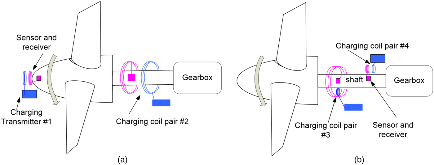
On the other hand, the radial positioning is practical for rotating components with larger dimension; two possible radial configurations are illustrated in Fig. 3(b). The receiver coil has a diameter bigger than the rotating shaft, and the stationary transmitter coil with a smaller dimension is fixed at a radial position over the rotating shaft (charging coil pair #3). This configuration has less concern in heating effect of the shaft material, but the coupling coefficient is undermined for the non-coaxial misalignment and the difference in coil diameter. Limited by the low coupling coefficient without magnetic core inside the transmitter coil, this configuration is not experimentally evaluated in this study for the less potential in link efficiency and power rating. However, the coil configuration of transmitter and multiple receiver coils of a similar size over the rotating shaft (charging coil pair #4) is investigated in this study. The charging power is intermittent due to the continuing alignment and misalignment of the rotating receiver coils relative to the static transmitter; supercapacitor is used to accumulate the intermittent power input in the receiver circuit.
A) Axial configuration for WPT
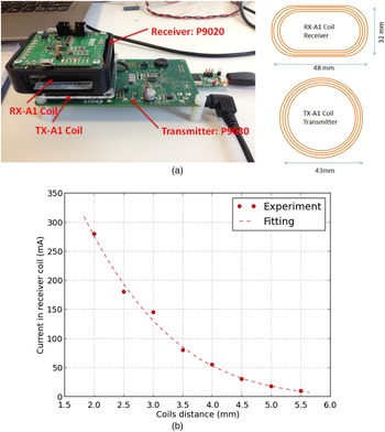
Several Qi evaluation kits are commercially available, e.g. TI bqTESLA Development Kit [41] and IDT 9030/9020 kit [42]. The highly integrated single chip devices of the IDT P9030 transmitter evaluation board and the IDT P9020 receiver demonstration board are selected for the current wireless charging evaluation experiments. The IDT P9030 uses the Qi standard compliant TX-A 1 transmitter coil, which has a diameter of 43 mm. The TX-A 1 coil is driven by a 19 V direct current (DC) power adapter via a half-bridge inverter, which converts the DC into AC form to excite the coil. The switching frequency of the inverter is between 110 and 205 kHz at a constant duty cycle of 50%.
The performance of the IDT wireless charging kit is evaluated for the allowance of spatial misalignment and the power rating dependency on the charging distance. The IDT P9020 incorporates a Qi standard compliant RX-A 1 coil, which has a length of 48 mm and a height of 32 mm [42], as illustrated in Fig. 4(a). Notably, the revised Qi specification version 1.1 has 12 standard transmitters. The receiver is powered by the RX-A 1 coil and transfers the power to the external load through a full bridge rectifier, and the transferring efficiency is around 75%. The designed DC output of the P9020 is 5 V at 1 A; this power rating is sufficient to power variety of wireless sensors. The active charging distance is stated as 5 mm in Z-axis (co-axial direction normal to the non-contact transmitter and receiver coils plane) according to the specification, but there is no statement on the allowance on X and Y axis (lateral directions). The charging distance allowances without shutdown for wireless charging are measured by a digital calliper as 17 mm, 13 mm for X- and Y-axis, respectively, at Z = 1 mm. The minimum spatial freedom is 5.9 mm in Z-axis without lateral misalignment in X- or Y-axis. These misalignment tolerances are sufficient for deployment on rotating machines without significant vibration. In order to obtain a high power rating, the charger has to be close to the receiver, according to equation (3) and the experimental measurement of nonlinear relationship of power rating and charging distance (see Fig. 4(b)).
(a) Demonstration of Qi Standard compliant charger and coils; (b) power rate versus charging distance.

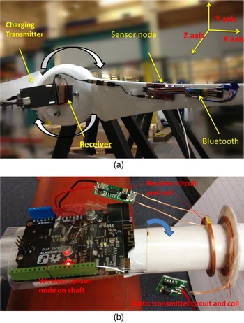
The axial positioning test (charging pair #1) has demonstrated the feasibility and reliability of charging the wireless sensor on a wind turbine test rig using the magnetic induction technology. The experimental setup for the axial positioning of wireless charging coils is indicated in Fig. 5(a). The transmitter is fixed in front of the turbine hub where the receiver is attached, and an acceleration sensor node with a HC05 Bluetooth radio module is bonded onto one of the blades. The acceleration is measured by an on-board ADXL335 3-axis acceleration sensor of an MSP430 FRAM5739 microcontroller board for several rotations. The continuous transfer of acceleration readings via Bluetooth radio confirms that the IDT wireless charging kit, or other Qi standard compliant products, can provide adequate power to the wireless sensor node on rotating machines for this axial configuration.
Experimental setup of WPT with co-axial coil configurations; (a) Qi Standard compliant coils at the shaft end; (b) custom transmitter and receiver coils around the shaft.

Instead of the Qi standard compliant coils installed at the shaft end, custom transmitter and receiver coils can be applied surrounding the rotating shaft. As illustrated in Fig. 3(a), wireless charging coil pair #2 can be flexibly mounted around the rotating shaft, given the custom coils matching the designed self-inductance of transmitter and receiver circuits. The self-inductance of the custom coils with a mean coil diameter of 38 mm is confirmed by the Fluke PM6303 LCR meter as 30 µH; the resonating frequency is 75 kHz measured by digital oscilloscope. This charging setup has a variable powering performance of 20–600 mA at 5 V after rectifier, measured by the voltage-ampere method using a high power rating resistor. Similar trend of reduced power rating is observed if the co-axial distance increases from 1 to 20 mm. Furthermore, the custom wireless charging coil pair is tested on the Aluminum shaft of a small tribology test rig, shown in Fig. 5(b). It is feasible to power a Bluetooth wireless sensor node, without interruption of wireless communication. In contrast to the non-resonance WPT, the voltage ratio and link efficiency is stable for k from 0.9 to 0.3 which corresponds to the coil separation distance from 2 to 12 mm according to equation (3).
The inductive heating effect has been examined for this co-axial shaft-coil configuration. In addition to theoretical prediction of eddy current heating, experimental test of the custom coils is conducted on Aluminum cylinder and iron pipe. Without connection any load on secondary circuit, 0.1 A at 10 V on DC power supply is consumed on the primary circuit, insensitive to coil separation distance. Insertion of 20 mm diameter Aluminum rod increases the DC current input from 0.10 to 0.18 A at 10 V, for the coil separation distance of 16 mm. Once the Aluminum cylinder is sliding in, the receiver rectifier output drops to 2 V, as the receiver coil voltage drops. If the coil separation distance is reduced from 16 to 5 mm, the 5 V output regains after the receiver rectifier. Moreover, 0.5 W transferred to load on the secondary circuit is possible with closer coil gap of 3 mm.
Increased transmitter DC power supply and dropped voltage on receiver coil are found for the iron pipe. About 3 W (0.3 A at 10 V) is consumed as eddy current and hysteresis loss for a hollow low carbon steel pipe with a wall thickness of 2 mm and outer diameter of 32 mm, for the coil separation distance of 16 mm. Compared with Aluminum cylinder core, more heat loss but similar receiver voltage drop is observed for the high magnetic permeability iron pipe. Ferro-magnetic shaft material as a magnetic core can alter the magnetic flux and potentially improve the inductive coupling. In addition, it is confirmed by different diameter of steel pipe that the eddy current loss increases dramatically with the cross-section of shaft. Due to the high thermal conductive coefficient for metal material, the experiment shows no observable temperature rise for such a low power rating. Although the metal shaft decreases the transferring efficiency significantly, it is feasible to deliver reasonable power to the wireless sensor node on the rotating metal shaft with low magnetic permeability. It is recommended to optimize the resonance frequency or coil-shaft positioning, to reduce the power loss. Magnetic shielding is also worth of investigation in the future study.
B) Intermittent energy gathering and storage circuit
If the co-axial configurations of the charging coils are impractical for some large dimension rotating components or metal heating issue, the radial configurations in Fig. 3(b) are worth of investigation. It should be noted that the pairing of a small transmitter coil with a bigger receiver coil winding around the rotating shaft is an optimized configuration. Compared with the configuration of a bigger transmitter coil and a smaller receiver coil, a smaller transmitter coil reduces the electromagnetic interference to electronic components nearby. The difference in coil diameter and misalignment lead to the low coupling coefficient. The charging pair #3 is less efficient for the lower coupling coefficient, and most energy is wasted in the transmitter coil if its diameter is significantly smaller than the receiver coil. In theory, the steady WPT process is similar with the axial charging coil pair, except for a smaller inductive voltage ratio and power rating. However, the low coupling coefficient k suggests magnetic resonance with a low power loss magnetic core could be a better solution for higher power rating and efficiency, which is out of the scope of this paper.
Alternatively, the charging pair configuration #4 is investigated by charging and receiving coils of similar size. Although the high coupling coefficient is guaranteed by the small coil distance in the close alignment position, the continuing alignment and misalignment results in the intermittent power input to the receiver coil. Storage of the intermittent input energy is a practical challenge for powering the sensors continuously on rotating components. Nevertheless, the Qi standard defines the receiver detection and communication procedure, which requires a significant duration to setup the charging even if the coils are aligned. Therefore, a self-built charging circuit is established for instant charging without the delay of complex communication.
Supercapacitor is preferred over Lithium ion battery, in order to gather the intermittent energy input. Lithium ion batteries have limited recharging cycles so pulse charging may reduce its lifetime dramatically [Reference Simon43]. Besides, the charging processes of Lithium ion battery are complex, and there is a threshold voltage to trigger the charging [Reference Cericola, Ruch, Kötz, Novák and Wokaun44]. In contrast, the emergent technology of supercapacitor can provide instant energy storage capability. A supercapacitor works in a similar manner with generic capacitors but offers larger capacitance and lower equivalent series resistance. Consequently, it scavenges energy immediately once there is a higher voltage applied across its terminals. The characteristic of high capacitance and low resistance is ideal to perform the instantaneous charging as requested in the current study [Reference Abbey and Joos45, Reference Choi, Ho, Liu and Hui46].
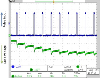
Intermittent energy gathering and instant storage by the supercapacitor (Cooper Busmann PB series. 1 F, 0.5 Ω) has been validated by a prototype circuit. A series of energy pulse is generated by a 5 V DC power supply (Thander Instruments TS32021S) controlled by a MOSFET switch. The square-wave control signal for the MOSFET switch has a duty cycle of 10%. The pulses charge the supercapacitor, which continuously stores the intermittent energy input and delivers a stable DC output voltage via a low-dropout regulator (LDO).
Figure 6 presents the voltage variation from the experimental circuit for pulse energy gathering. The voltage across the supercapacitor (at the bottom of Fig. 6) is monitored with the reversed polarity for clear comparison with the input pulse, which is in the normal polarity (on the top of Fig. 6). When the supercapacitor is fully charged, the voltage across the supercapacitor increases to 5 V (shown in the downward axis at the bottom of Fig. 6). The experimental result demonstrates a high energy charging rate; the first several pulses can charge the supercapacitor up to the rated voltage of 5 V. After the supercapacitor voltage reaches 3.6 V, the LDO will output a constant 3.3 V voltage to power up the MSP430 FRAM5739 microcontroller. Due to the low power consumption of the MSP430 microcontroller, the discharging is illustrated as slow voltage dropping when no pulse energy is available. The voltage drops about 0.2–0.4 V before the next pulse input; this limited voltage fluctuation can guarantee the continuous output of 3.3 V from the LDO. Consequently, the sensor can be continuously powered, despite the intermittent energy input.
Result from prototype circuit for pulse energy gathering by supercapacitor.

C) Prototype circuit for the radial configuration
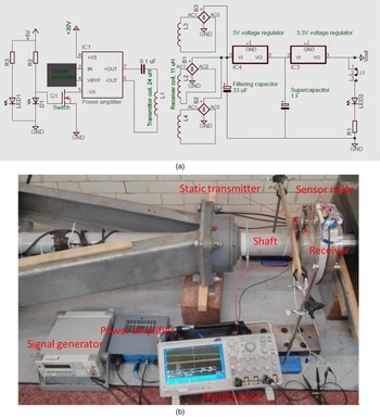
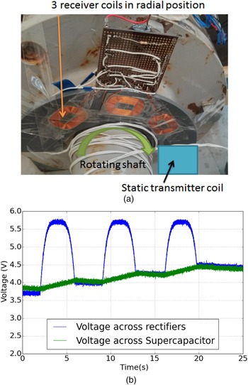
The radial positioning (coil pair configuration #4) provides a flexible configuration for most rotating machines, as illustrated in Fig. 3(b), but sufficient power rating should be guaranteed. The design of multiple receiver coils circuit [Reference Cannon, Hoburg, Stancil and Goldstein47] is promising to increase the power transferred to the wireless sensor node on the rotating shaft (see Fig. 8(a)). To exclude the interference between the multiple receiver coils, each coil has its own rectifier but shares the filtering capacitor and the supercapacitor after the full-bridge rectifiers, shown in the circuit schematic in Fig. 7(a). Multiple receiver coils are arranged in different radial positions of the rotating shaft; the duty cycle of effective charging increases proportionally with the number of the coils, see Fig. 8(a).
(a) Schematic of single transmitter coil and multiple receiver coils for radial configuration; (a) schematic of transmitter and receiver circuit; (b) experimental setup on a small scale wind turbine test rig.

(a) Prototype circuit with multiple receiver coils; (b) voltages monitoring for wireless charging on a rotary shaft.

In order to bypass the charging delay due to communication, a self-built induction excitation and receiving circuit is constructed with Qi-compliant standard transmitter and receiver coils, as illustrated in Fig. 7(a). The circuit requires a 150–180 kHz square wave signal to excite a Qi-compliant TX-A 1 coil to induce voltage across the receiver RX-A 1 coils and in turn energizes a light emission diode (LED) indicator after the power conditioning circuit. A 30 W power amplifier amplifies the square wave from the RIGOL DG1022 function generator, which has a peak-to-peak voltage of 2.5 V. After the full bridge rectifier, a 33 µF filtering capacitor is incorporated to smooth the output of the rectifier. The following 5 V voltage regulator is used to charge the supercapacitor and isolates the supercapacitor from any potential over-voltage. Another 3.3 V voltage regulator will power the load of this wireless energy receiver, either LED as an indicator or wireless sensor node. In the current experiments, the receiver circuit is bonded to the Gaia 11 kW wind turbine test facility while the transmitter coil is fixed over the main drive shaft with a 4 mm gap with the receiver coil in alignment; see Fig. 7(b).
Furthermore, to reduce the energy waste as resistive loss in the primary coil when the receiver coil is not aligned [Reference Matias, Cunha and Martins32], the excitation of the transmitter coil is switched on and off by a pair of infra-red LED and photonic transistor (see Fig. 7(a)). The emission from the LED, which can be reflected by the highly reflective tape on the receiver board results in the reduced resistance of the photo transistor. Thereby, the rising gate voltage of the MOSFET will switch on the power amplifier module only if the receiver board is facing the infra-red LED and photonic transistor pair. In other words, the transmitter coil is excited only if any receiver coil is moved into the charging range.
Figure 8(b) demonstrated the process wireless charging to three receiver coils in a single rotation cycle; the voltage cross the rectifiers rises simultaneously as the receiver coil moves into the charging range. Voltage signals are wired to a digital oscilloscope, which gives higher sampling rate data acquisition. Once the voltage of the rectifiers output surpasses that of the supercapacitor, effective charging continues until the receiver coil phases out. This process repeats as the next receiver coil moved into the active charging range of the static transmitter. The voltage across the supercapacitor rises about 0.3 V for each charging pulse, while the voltage drop is not significant due to the low power consumption of LED indicator. The fast response of the receiver coil together with the pulse gathering circuit makes the wireless charger applicable for the radial configuration of charger and receiver on rotating components. The power rating delivered by the current prototype circuit is up to 2.5 W for static close alignment; while the average transferred power rating is only 0.015 W for the tested shaft speed of 1 rotation per minute.
Higher power rating is achievable via several approaches. Firstly, the excitation voltage across the transmitter coil can be increased. The transmitter coil's AC voltage is approximately one-third of that of the IDT charger coil. The stronger transmitter excitation can boost the power rating significantly, if the electrical safety of the transmitter circuit design is guaranteed. Secondly, the distance between the receiver coil and transmitter coil, which is 4 mm on average in the current setup, can be reduced further to increase the power rating. Otherwise, the resonant receiver circuit may increase power rate and extend the effective charging time of each pulse. In addition, a rectangular receiver coil may increase the effective charging time. The power input from the receiver coil is not a square wave pulse (see Fig. 8(b)), if the receiver coil is rotating with the shaft. Since the voltage output from the rectifier is sensitive to the relative positioning of transmitter and receiver coils, less power is transferred in the phase-in and phase-out stages for the receiver coil. To make thing worse, effective charging will only start if the output voltage of the rectifier is higher than that of the supercapacitor, when both coils are reasonably aligned. Therefore, Qi standard compliant receiver coils are deployed with the longer edge along the circumferential direction in the current experimental study, and custom receiver coils with a bigger aspect ratio can increase the duration of coil alignment and the charging time for each receiver coil.
IV. CONCLUSION
In this paper, popular technologies and industrial standards for WPT are compared, and magnetic induction solutions are investigated for charging wireless sensors on the rotating machines. A Qi standard compliant wireless charging solution and a circuit with custom inductive coils are validated experimentally for continuous wireless sensor charging for the co-axial coil-shaft configurations. The co-axial configurations are recommended for WPT to wireless sensor nodes on rotating machines for the convenient setup and reliable power transfer.
Besides the co-axial configurations of transmitter and receiver coils, a radial configuration is experimental tested. The challenge of gathering and storing intermittent energy input from receiver coils at the radial positions of rotating machines is addressed by supercapacitor, and an experimental circuit using a supercapacitor to store the intermittent power input is designed and validated. Based on this circuit, multiple receiver coils are demonstrated as effective to increase the power rating for WPT design for the radial coil configuration.
FINANCIAL SUPPORT
This research received no specific grant from any funding agency, commercial or not-for-profit sectors.
CONFLICT OF INTEREST
None.
 Qingfeng Xia obtained his Ph.D. degree from the University of Manchester in March 2012. Currently, he is a Research Associate at the Department of Engineering Science, the University of Oxford. His research interests include fluid visualization, condition monitoring of turbomachines, and sensor and instrumentations.
 Longyang Yan received the B.Eng (2012) and M.Sc. degree (2013) from University of Strathclyde, UK. He is currently working for the China subsidiary of Safe Engineering Services & technologies Ltd (SES-China). His research interests include the computation of EM field, EMI analysis & power system grounding.