I. INTRODUCTION
Multiple-input-multiple-output (MIMO) technology, with good performance of improving channel capacity and mutual coupling, has been arousing heated attention [Reference Kaiser, Feng and Dimitrov1]. Since 2002, ultrawideband (UWB) technology has been widely studied and applied in wireless systems because of its attractive features (low power, low cost, etc.) [2]. MIMO technology was proved to be an effective solution to provide excellent capacity in UWB systems. So it is very promising to combine UWB and MIMO, named UWB–MIMO. But there are two important issues should be well settled for UWB–MIMO systems. To keep compact volume, elements must be placed closely then mutual coupling was increased inevitably. The second issue is some systems, which frequencies exist in 3.1–10.6 GHz may severely affect the UWB system, such as WiMAX (3.3 GHz–3.7 GHz), WLAN (5.15–5.35, 5.725–5.825 GHz), and X-band (7.25–7.75 GHz).Thus, designing UWB–MIMO antennas with multiple rejected bands and low-port coupling functions is imperative.
Until now, many studies to combat mutual coupling of UWB–MIMO antennas have been discussed [Reference Kumar, Krishna and Kushwaha3–Reference Huang, Liu, Zhang and Gong10]. In [Reference Kumar, Krishna and Kushwaha3], a compact size of 46 mm × 32.6 mm MIMO/diversity antenna for UWB applications was introduced. A TH-like structure was applied to have better port isolation, which was less than −20 dB. In [Reference Zhang and Pedersen4], an UWB–MIMO antenna of size 35 mm × 33 mm was designed. Neutralization line was used to achieve isolation more than 22 dB, but the antenna only covered 3.1–5 GHz operation band. An 18 mm × 36 mm slot MIMO/diversity antenna for UWB applications was proposed in [Reference Chandel and Gautam5]. By extruding a T-shaped stub in the ground plane, low mutual coupling of less than −20 dB was obtained from 2.9 to 20 GHz. Some metal strips also can be applied to reduce isolation [Reference Li, Cheung and Yuk6–Reference Tang and Lin9]. In ref. [Reference Huang, Liu, Zhang and Gong10], two elements were placed vertically and then mutual coupling is less than −20 dB.
Recently, many technologies about designing band stop function for UWB systems have been studied, such as embedding various slots on radiator [Reference Wu, Wei, Shi and Li11], introducing DGS (defected ground structure) [Reference Li and Hei12]. However, the above UWB–MIMO antennas [Reference Kumar, Krishna and Kushwaha3–Reference Huang, Liu, Zhang and Gong10] have realized no more than triple notched bands. In [Reference Kumar, Krishna and Kushwaha3, Reference Zhang and Pedersen4], there have no notched band function, [Reference Chandel and Gautam5] filters 4.17 GHz C-band, and [Reference Li, Cheung and Yuk6, Reference Kang, Li, Wang and Shi7] filter 5.5 GHz WLAN. In [Reference Li, Chu, Li and Xia8, Reference Tang and Lin9], antennas mitigate two bands of WiMAX and WLAN. The authors of [Reference Huang, Liu, Zhang and Gong10] designed triple notched bands to block WiMAX, WLAN, and X-band. Noted that there are lower band of 5.15–5.35 GHz and upper band of 5.725–5.825 GHz for WLAN, but [Reference Li, Cheung and Yuk6–Reference Huang, Liu, Zhang and Gong10] notch the whole WLAN (5.15–5.825 GHz), thus some useful frequency bands are also filtered. Due to limited spectral resource, filtering lower WLAN and upper WLAN can improve spectrum utilization. Therefore, it is necessary to designing compact quad-band-notched and low-port coupling UWB–MIMO antennas for filtering WiMAX, lower WLAN, upper WLAN and X-band.
In this paper, a quad-notched band UWB–MIMO antenna was introduced. With a compact size of 30 × 45 mm2, the system covers 3.1 – 10.6 GHz except four stop bands: 3.25–3.9, 5.11–5.35, 5.5–6.06, and 7.18–7.88 GHz. Two L-shaped slots are etched symmetrically on the radiator to notch 3.5 GHz WiMAX, complementary split-ring resonators (CSRR) to obtain lower WLAN and upper WLAN, and C-shaped stubs to filter 7.5 GHz X-band. Three metal strips are placed on the ground plane to relief mutual coupling, and isolation is less than −18 dB. This simple compact UWB–MIMO antenna can filter four notched bands. To my knowledge, literatures of four notched band UWB–MIMO antennas are relatively scarce. Filtering lower WLAN and upper WLAN can improve the spectral efficiency. And high isolation of −18 dB improves channel capacity and communication quality. Simulations and measurements results prove that the antenna is useful in UWB systems. Details are given as below.
II. ANTENNA DESIGN
A) Configurations
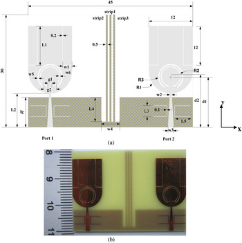
Figure 1 exhibits the configurations and photo of fabricated antenna. The antenna is etched on a cheap FR4 PCB substrate (dielectric constant of 4.4, loss tangent of 0.025, and thickness of 0.8 mm) and occupies 30 × 45 mm2. Each radiator comprises a rectangular radiating patch with a semi-circle at bottom and is fed with a tapered microstrip line. Port isolation between two elements is enhanced effectively by three metal strips extending from common ground plane. Impedance bandwidth can be adjusted by L 4 × w 4 notched block (L 4 = 6.5 mm, w 4 = 5 mm). Two L-shaped slots are inserted in each element to filter 3.5 GHz WiMAX. Since CSRR exhibit negative effective permittivity or negative magnetic permeability, it is employed to notch lower WLAN and upper WLAN; and to create the fourth notched band (7.18–7.88 GHz), a pair of C-shaped open stubs is located symmetrically at both sides of the tapered feed line. Although it is similar to the element in [Reference Huang, Liu, Zhang and Gong10], which realized triple notched bands, some details are different. Firstly, the elements are arranged horizontally to save space, and the overall size is 30% smaller than the antenna in [Reference Huang, Liu, Zhang and Gong10]. More importantly, based on CSRR slots and C-shaped subs, two L-shaped slots are inserted to create a notched band, and then quad-notched bands are obtained. Thirdly, CSRR slots in the design are curved to filter lower WLAN and upper WLAN (in [Reference Huang, Liu, Zhang and Gong10], they are used to block 3.5 GHz WiMAX and 5.5 GHz WLAN). The 5.25 GHz lower WLAN and 5.8 GHz upper WLAN are adjacent, so the inner ring of the CSRR is close to the outer ring. In this case, it is more difficult to design the parameters of CSRR.
(a) Sketch of the proposed antenna and (b) fabricated antenna.

To get notched band, usually the length of resonator is quarter-wavelength or half-wavelength of corresponding notched frequency. The total length of L-shaped slots can be worked out by equation (1). And the total lengths of other three structures are determined by equation (2).
 $$L_{total} = \displaystyle{c \over {{\rm 4}f_{notch}\sqrt {{\rm} \varepsilon _{eff}{\rm}}}}, $$
 $$L_{total} = \displaystyle{c \over {{\rm 2}f_{notch}\sqrt {{\rm} \varepsilon _{eff}{\rm}}}}, $$
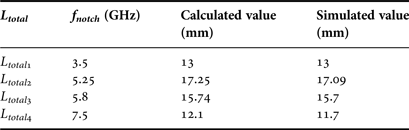
where L total is the total length of resonator, c denotes the light speed, f notch denotes center frequency of rejected bands, and ε eff = (ε r + 1)/2 is the effective dielectric constant. By equations (1) and (2), Table 1 lists calculated L total , simulated values are also given for comparison. From Table 1, it can be observed that simulated values are very close to calculated values, validating the design concepts.
Comparison of calculated and simulated total length.

Computer simulations using CST Microwave Studio have been used to analyze the effects on the antenna characteristics. The final optimum antenna parameters are set as follows (unit, mm):
L 1 = 10.4, L 2 = 9, L 3 = 2.9, L 4 = 6.5, L 5 = 4.4, R 1 = 6, R 2 = 2.74, R 3 = 3.42, w 1 = 2.6, w 2 = 0.5, w 3 = 1.6, w 4 = 5, w 5 = 0.3, w 6 = 0.2, l g = 8, d 1 = 13.45, d 2 = 13.5, g 1 = 0.9, g 2 = 3.45.
B) Effect of strips 1, 2, and 3
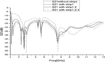
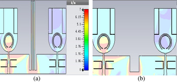
Considering consistency of port1 and port2, we only analyze S 21 for simplicity. Mutual coupling can be effectively reduced with three metal strips, because the strips can be taken as a reflector [Reference Zhang, Ying, Xiong and He13]. As shown in Fig. 2, without strips, S 21 is above −15 dB in the whole band, mutual coupling is strong. When strip 1 is added, S 21 is less than −15 dB, and isolation is enhanced. With the increase of strips, mutual coupling is reduced obviously. It can be observed, S 21 is less than −18 and 20 dB in most of UWB band with strips 1, 2, and 3. Moreover, to better understand the function of strips 1, 2, and 3. Figure 3 illustrates surface current distributions at 6.5 GHz when port 1 is excited. For comparison, the situations without strips are also shown in Fig. 3. One sees that without strips 1, 2, and 3, a large quantity of current flows to port 2 via the common ground. On the contrary, with strips 1, 2, and 3, the current mainly concentrates around left system, and the current flowing to another port is blocked, and then the number of current is much less on the right antenna system. Therefore, these three metal strips help gain better isolation.
S 21 when number of the strips varies.

Surface current distributions on the radiating patch, (a) with strips and (b) without strips.

C) Effect of slots and stubs
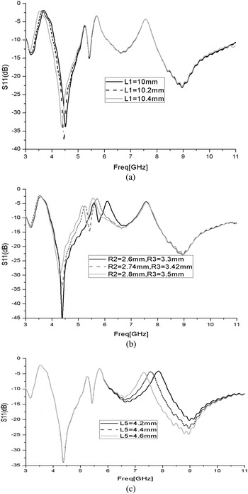
To better understand the effect of the slots or stubs on S 11, some key parameters are chosen to discuss. The effect of different L 1 on S 11 is plotted in Fig. 4(a). Increasing L1 from 10 to 10.4 mm, central frequency of the first stop band is reduced from 3.7 to 3.5 GHz, which can be derived from formula (1). Variation curves of the second and third notched bands with different values of (R 2, R 3) are illustrated in Fig. 4(b). By changing the lengths (R2, R3) from (2.6,3.3 mm) to (2.8, 3.5 mm), the second notched band shifts from 5.5 to 5.15 GHz, and the third notched bands varies from 6.2 to 5.6 GHz. From Fig. 4(c), we find that when L 5 is increased from 4.2 to 4.6 mm, the fourth notched frequency decreases from 7.8 to 7.2 GHz. These simulated results reveal that each rejected band can be controlled individually.
Simulated S 11: (a) effects of L 1; (b) effects of R 2 and R 3; (c) effects of L 5.

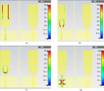
To explain the generation of the notched bands, the current distributions on the antenna at 3.5, 5.25, 5.8, and 7.5 GHz are shown in Fig. 5. As illustrated in Fig. 5(a), at 3.5 GHz WiMAX band, since strongest current is found around L-shaped slots, current propagation is prevented and the antenna cannot radiate, which leads to the first notched band. In Figs 5(b) and 5(c), at 5.25 GHz lower WLAN and 5.8 GHz upper WLAN, the current mainly concentrates around CSRR, which means CSRR has important effect in the formation of 5.25 and 5.8 GHz notched bands. As shown in Fig. 5(d), the current is stronger at the middle of the C-shaped stubs, the impedance is nearly zero; and the current approaches zero at the ends, the impedance is very high. The mismatch impedance causes the fourth notched band.
Surface current distributions when port 1 is excited: (a) 3.5 GHz; (b) 5.25 GHz; (c) 5.8 GHz; (d) 7.5 GHz.

III. RESULTS AND DISCUSSIONS
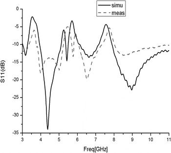
The proposed UWB–MIMO antenna is fabricated and tested. The measurements of S parameters were carried out with Agilent E8362B network analyzer. For consistency of ports 1 and 2, we only discuss S 11 and S 21. The measured and simulated S 11 are displayed in Fig. 6. The results show that the antenna keeps S 11 < −10 dB from 3 to 11 GHz, which covers UWB band, but except notch frequency of 3.25–3.9, 5.11–5.35, 5.5–6.06, and 7.18–7.88 GHz. That means the UWB–MIMO antenna can effectively eliminate interference from WiMAX, lower WLAN, upper WLAN, and X-band.
Simulated and measured S 11 of the proposed antenna.

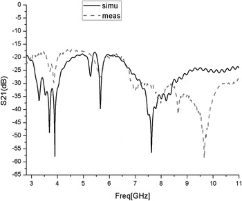
Figure 7 shows S 21 is less than −18 dB in the 3–11 GHz band, and below −20 dB in most of the band. This proves that the antenna meeting FCC UWB standard can be applied for MIMO systems. Measurement and simulation results are in good agreement with each other in Figs 6 and 7. However, some deviations between them occur. For instance, in Fig. 6, the curves match well at lower frequencies, but at higher frequencies, there are deviations. Besides, in Fig. 7, the measurement S 21 is a little higher at low-frequency band, but lower at high-frequency band. The cause of the deviations may be attributed to the loss tangent, fabrication errors and the jointing of SMA (Small A Type) connector.
Simulated and measured S 21 of the proposed antenna.

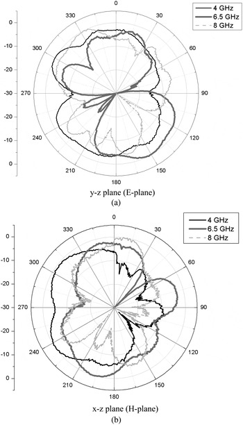
In addition, measured normalized radiation patterns about the y–z plane (E-plane) and the x–z plane (H-plane) for port 1at 4, 6.5, and 8 GHz are depicted in Fig. 8. From Figs 8(a) and 8(b), it can be found that the antenna behaves nearly like a dipole in the E-plane and a nearly omnidirectional radiation pattern in the H-plane. Because of symmetrical structure, when port 2 is excited, patterns of E-plane are similar to Fig. 8(a) and the H-plane patterns are mirror-symmetrical to Fig. 8(b) about the y–z plane. Due to measurement environment and radiation of C-shaped stubs, radiation pattern is deteriorated, especially at high frequency.
Measured normalized far-field radiation patterns for port 1; (a) the y–z plane (E-plane); (b) the x–z plane (H-plane).

To better evaluate MIMO diversity characteristic, [Reference Blanch, Romen and Corbella14] provides an easy formula to calculate envelope correlation coefficient (ECC) for two-port MIMO system.
 $$\rho _e = \displaystyle{{{\left \vert {S_{11}^* S_{12} + S_{21}*S_{22}} \right \vert} ^2} \over {(1 - \vert S_{11} \vert ^2 - \vert S_{21} \vert ^2)(1 - \vert S_{22} \vert ^2 - \vert S_{21} \vert ^2)}}.$$
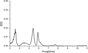
ECC results calculated after obtaining measured S 11, S 21 are illustrated in Fig. 9 for port 1. The ECC results are below 0.02 across 3.1–10.6 GHz UWB band.
Measured ECC of the proposed antenna.

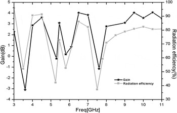
Figure 10 shows gain and radiation efficiency of the proposed antenna when Port 1 is excited. With the above band-notched technique, the gain is decreased sharply at the notched bands, while moderate gain is achieved over the 3.1–10.6 UWB band. It also can be observed that efficiency of port 1 is above 75% in the whole band except four minimum values at the rejected bands.
Antenna gain and radiation efficiency.

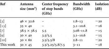
At last, Table 2 shows comparisons of the antenna and some other UWB–MIMO antennas. Compared with [Reference Kumar, Krishna and Kushwaha3], the proposed work is smaller and has higher isolation. Although the antennas in [Reference Zhang, Ying, Xiong and He13, Reference Kang, Li, Wang and Shi7] have a little better isolation, they are large in size and have no notched function or only filter 5.5 GHz WLAN. As for the antenna in [Reference Tang and Lin9], it has a little smaller size and better isolation; however, it only mitigates two bands of WiMAX and WLAN. Compared with [Reference Huang, Liu, Zhang and Gong10], this work has a smaller size, higher isolation, and one more rejected band though the bandwidth is narrower. It is clear that the proposed UWB–MIMO system can not only realize quad-notched band, but also has high isolation and relatively compact size.
Comparisons of the antenna and other UWB–MIMO systems.

IV. CONCLUSION
In the paper, a compact quad-notched band UWB–MIMO antenna has been investigated. The desired four notched bands can be achieved by inserting two similar L-shaped slots, CSRR structure and C-shaped stubs. The results indicate that the system has a wide bandwidth of 3–11 GHz, except the notched bands of 3.25–3.9, 5.11–5.35, 5.5–6.06, and 7.18–7.88 GHz. With simple decoupling structure of three metal strips on the ground, high isolation was easily achieved less than −18 and −20 dB in most of 3.1–10.6 UWB band. Moreover, ECC of less than 0.02 and good radiation pattern, thus making it useful for UWB systems.
ACKNOWLEDGEMENT
The authors acknowledge electromagnetic microwave laboratory of Hua Zhong Normal University for technical support and help.
 Ling Wu received the B.S. degree in Huazhong Normal University, Wuhan, China, in 2004, and received the M.S. degree in Huazhong Normal University in 2007. Currently, she is a lecturer in Wuchang University of Technology, Wuhan, China. At the same time she is pursuing Ph.D. from Huazhong Normal University. Her main research includes microtrip-fed antenna design and signal processing.
 Yingqing Xia received the M.S. degree in Huazhong Normal University, Wuhan, China, in 1997 and received Ph.D. degree in Huazhong Normal University in 2003. From 2006 to 2007, he engaged in postdoctoral research in the University of Oxford. Presently he is a Professor in Huazhong Normal University. He is interested in microwave circuits, embedded software and hardware systems and applications.