Introduction
Polarization of the electromagnetic (EM) waves is a crucial factor to receive the EM waves efficiently by the receiving antennas. For a communication to be effective, the transmitting and receiving linear antennas must have the same type of polarization, which is not always the case in real-world situations. To overcome this, circular polarization (CP) antennas have been used at the front end of the receivers in various applications, but it is hard to achieve the CP feature over the wide range of frequencies. To meet these challenges, radio frequency engineers conceptualized the polarization converters, which are also known as polarizers. In fact, these are the periodic structures with the capability to transform the polarization state of an EM wave to get desired polarization in specific bands [Reference Lerner1]. Hence, polarization converters find their applications in several areas including wireless communication, radar sensing, astronavigation, antennas, [Reference Chen, Taylor and Yu2] etc. Polarization conversion could be accomplished through traditional techniques: using birefringence wave plates [Reference Chin, Lu and Cui3]; liquid crystals [Reference Xiong, Jiang, Hu, Hu, Wang, Peng and Wang4], Faraday effects [Reference Zhao and Alù5], etc. However, these techniques had drawbacks of large thickness and narrow bandwidth that restrict its practicality in various applications. Planar structures such as metasurfaces are then investigated successfully to mitigate the complexity of the wireless systems [Reference Holloway, Kuester, Gordon, O’Hara, Booth and Smith6]. With the advancement, these planar surfaces are developed as polarization converters to serve multiple functions such as cross-polarization conversion (CPC) [Reference Chin, Lu and Cui3], linear polarization to circular polarization (LPCP) conversion [Reference Zhang, Li and Xie7], radar cross section (RCS) reduction [Reference Fu, Han, Liu, Sun and Lu8], and mutual coupling reduction of MIMOantennas [Reference Das and Mandal9].
Depending on whether the receiver is placed on the same side of the polarizer or on the opposite side, polarization conversion can occur in both reflection and transmission modes.
However, since copper film is placed on the back side to guarantee no transmission, reflective-type polarization converters are simpler to design. Reflection-type polarization converters are popular for exhibiting larger bandwidth in LPCP conversion [Reference Lin, Lv, Guo, Liu, Ji and Wu10–Reference Kundu, Singh, Singh and Chakrabarty12], CPC for RCS reduction [Reference Mei, Ma, Lu and Zha13–Reference Chatterjee, Mohan and Dixit15], and hybrid polarization conversion [Reference Wang, Liu, Kong, Zhang, Yu, Wen and Wang16, Reference Dutta, Ghosh, Yang and Zhang17]. Literature studies suggest that the anisotropic metasurfaces are helpful to exhibit CP characteristics in specific bands [Reference Lin, Lv, Guo, Liu, Ji and Wu10–Reference Kundu, Singh, Singh and Chakrabarty12]. Certain metasurfaces exhibit cross-polarization performance, e.g. double U-shaped metasurface [Reference Mei, Ma, Lu and Zha13], double split-ring resonator metasurface [Reference Qi, Zhang, Liu and Deng14], and modified concentric double-square ring resonator [Reference Chatterjee, Mohan and Dixit15]. In order to obtain RCS reduction properties, the Panchratnam Berry 2-bit coding metasurface is employed [Reference Qi, Zhang, Liu and Deng14]. Frequency selective surfaces are also investigated to display multifunctional characteristics in different bands [Reference Wang, Liu, Kong, Zhang, Yu, Wen and Wang16, Reference Dutta, Ghosh, Yang and Zhang17]. For example, the identical structure can transform a linearly polarized wave into cross- and circularly polarized waves in discrete bands. As a result, similar polarization converters are helpful for converting the polarization state across a wide bandwidth according to the needs of the applications. It is important to discuss the applications of polarization converters in satellite communications as well which is one of the most potential applications. In order to prevent interference, the satellite needs nonadjacent frequencies for both uplinking and downlinking, as well as a specific kind of handedness in CP. This is covered in the reflective-type converters [Reference Nama, Nilotpal, Bhattacharyya and Jain11] and the transmissive-type converters [Reference Naseri, Matos, Costa, Fernandes and Fonseca18], and it has been made possible by the use of polarization converters integrated with antennas. Though tuning the bands for the designated frequency bands of satellite communications is an extremely difficult and complex task.
In this paper, a modified dumbbell-shaped unit-cell is chosen to develop metasurface-based polarization converter. The dumbbell-shaped structure is placed diagonally with respect to the substrate to achieve anisotropic nature which is essential to change the state of polarization. Owing to its unique design, careful selection of the structure parameters after meticulous optimization, the proposed polarizer can convert the wave polarization in five different bands. It exhibits CPC (y-to-x or x-to-y) over two bands: 4.74–5.12 and 9.12–13.48 GHz, where polarization conversion efficiency (PCE) is found greater than 90%. It also shows LPCP behavior in the three bands: 4.24–4.68, 5.24–8.64, and 13.72–15.14 GHz considering 3 dB axial ratio (AR) bandwidth. Further, the study of the phase difference between co- and cross-polarized reflected waves in the CP bands demonstrates that left-handed CP (LHCP) is obtained in the first band while it is right-handed CP (RHCP) in last two bands. The effectiveness of the intended metasurface structure, which transforms linearly polarized wave either into its orthogonal counterpart or circularly polarized waves over the entire 4−16 GHz band, is what makes the proposed work novel.
Unit cell geometry and principle of polarization conversion
Unit cell geometry
The proposed design is an amalgamation of three-layered structure. The top layer consists of a modified dumbbell-shaped structure kept diagonally over the top of the substrate. A tapered rod is terminated by semicircular stub on either sides and the resulting structure is termed as modified dumbbell. The curvature of the tapered rod (Larc) is the function of rod width (Ld) and it increases with Ld. This structure is created on a 3.2-mm-thin FR4 glass epoxy substrate with relative permittivity of 4.4 and loss tangent equivalent to 0.02. The 35-μm-thin copper acts as bottom layer of the substrate and it is responsible for complete reflection of the waves from the other side of the converter. Figure 1 shows the top and side views of the proposed unit cell specifying different structural parts along with the design parameters whose optimized values are given in caption. The working methodology of the proposed polarization converter is illustrated with the help of Fig. 1(b). It presents a sheet containing an array of identical unit-cells as described in Fig. 1(a). When a y/x-polarized EM wave impinges on this sheet, reflected waves are converted into x/y-polarized (cross-polarized) wave in 4.74–5.12 and 9.12–13.48 GHz bands. In addition, it is transformed into LHCP reflected wave over the frequency band of 4.24–4.68 GHz, and RHCP waves can be acquired as reflected waves within 5.24−8.64 and 13.72−15.14 GHz ranges.
(a) Side view, top view of the proposed polarization converter unit-cell. (a = 10 mm, Rd = 4.2 mm, Ld = 3.4 mm, Larc = 6.87 mm, and h = 3.2 mm), (b) Working methodology of the proposed polarizer surface.

Principle of operation
The proposed unit-cell is excited via means of Floquet port and is surrounded by the master-slave boundaries which are employed to enforce periodicity. Owing to its highly anisotropic nature, the proposed unit-cell is capable to convert the state of wave polarization from y-to-x and vice versa in two distinct bands. This condition is accomplished when there is high isolation between the magnitudes of co- and cross-polarized reflected waves. PCE accounts for the amount of the wave converted from y-to-x polarization [Reference Das and Mandal9]:
 \begin{equation}{\text{PCE}} = \frac{{r_{xy}^2}}{{r_{yy}^2 + r_{xy}^2}} \times 100\% \end{equation}
where  ${r_{xy}} = E_r^x/E_i^y$ signifies the reflection coefficient of cross-polarized wave while
 ${r_{yy}} = E_r^y/E_i^y$corresponds to the reflection coefficient of the co-polarized wave. To ensure the effective functionality of the polarizer as cross polarization converter, the PCE should be above or equal to 90% in the given working band [Reference Dutta, Ghosh, Yang and Zhang17].
In addition to this, proposed converter also exhibits LPCP characteristics in three relevant bands. This condition requires that the magnitude of the reflected co and cross-polarized waves should remain same, i.e.  $\left| {{r_{yy}}} \right| \approx \left| {{r_{xy}}} \right|$, providing phase difference (
 $\Delta \phi $) between them should be an odd multiple of 90°, i.e.
 $\Delta \phi = {\phi _{yy}}--{\phi _{xy}} = {\text{ }} \pm {\text{ }}90^\circ $. Here,
 ${\phi _{yy}}$ and
 ${\phi _{xy}}$ are the corresponding phases to the reflected waves. To evaluate the CP performance, AR is calculated in terms of the magnitudes of the reflectance and theirs phases and is given by the following equation [Reference Nama, Nilotpal, Bhattacharyya and Jain11]:
 \begin{equation}AR = \sqrt {\left[ {\,\frac{{{{\left| {{r_{yy}}} \right|}^2} + {{\left| {{r_{xy}}} \right|}^2} + \sqrt x }}{{{{\left| {{r_{yy}}} \right|}^2} + {{\left| {{r_{xy}}} \right|}^2} - \sqrt x }}\,} \right]} \end{equation}
where
 \begin{equation}x=\left|r_{yy}\right|^4+\left|r_{xy}\right|^4+2\left|r_{yy}\right|^2\left|r_{xy}\right|^2\text{cos}\left(2\Delta\phi\right)\end{equation}
Considering the aforementioned ideal conditions discussed in the above paragraph (CP), (2) and (3) provide AR as 1 which is equivalent to 0 dB and it regarded as perfect CP; however, it is not always the case in practice. Practically, 3 dB is taken as reference for the most of the communication applications [Reference Naseri, Matos, Costa, Fernandes and Fonseca18, Reference Khan and Eibert19].
Results and analysis
Two figures of merits were examined in the preceding section to describe the suggested polarizer’s polarization transformation performance. The corresponding numerical results for its capacity to convert LPCP and cross polarization separately are now shown in this section along with the parametric analysis and study of surface currents.
Cross polarization conversion
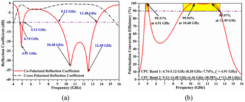
Figure 2(a) shows the reflection coefficient curve of both co- and cross-polarized waves in dB which has been calculated through  $20lo{g_{10}}\left| {{r_{yy}}} \right|$ and
 $20lo{g_{10}}\left| {{r_{xy}}} \right|$, respectively. To exhibit the cross-polarization characteristics, reflected wave must be oriented in orthogonal direction with respect to the direction of incident wave. Hence, high isolation is essential in amplitude levels of the co and cross-polarized reflected waves [Reference Zheng, Guo and Ding20, Reference Huang, Yang, Zhang and Luo21], which is reciprocating in Fig. 2(a). To demonstrate the amount of polarization conversion from y-to-x-polarized wave, Fig. 2(b) presents the simulated PCE, which has been calculated and plotted with the help of relation outlined in (1). It can be monitored that the proposed polarizer offers better than 90% PCE over the 4.74−5.12 and 9.12−13.48 GHz bands. In addition, maximum PCE of 99.31%, 99.94%, and 99.97% are obtained at 4.91, 10.48, and 12.49 GHz, respectively. This demonstrates that the proposed converter is capable to convert the state of linearly polarized wave into its orthogonal directions effectively in above two bands.
(a) Reflection coefficient of co- and cross-polarized waves and (b) Polarization conversion efficiency of the proposed polarization converter.

LPCP conversion
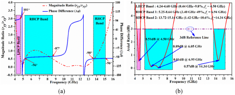
The proposed polarization converter can also exhibit LPCP behavior in three different bands due to its highly anisotropic nature. After tuning the design parameters meticulously, the proposed polarization converter is capable to convert the linearly polarized wave to circularly polarized waves in 4.24−4.68, 5.24−8.64, and 13.72−15.14 GHz bands. Previous studies suggest that the phase difference between two orthogonally polarized waves and their amplitude plays an important role in determining the type of handedness in CP. The phase difference of +90° or −270° implies for the LHCP while −90° or +270° corresponds to the RHCP [Reference Dutta, Ghosh, Yang and Zhang17]. Hence, the ratio of reflectance of co- and cross-polarized reflected waves and phase difference between them have been calculated numerically and portrayed in Fig. 3(a). It is worth mentioning to note that ratio of magnitude of co- and cross-polarized reflectance is equivalent to the ratio of orthogonal electric fields as displayed in papers [Reference Kulkarni, Sim, Gangwar and Anguera22, Reference Kulkarni, Sim, Poddar, Rohde and Alharbi23].
(a) Reflectance magnitude ratio and phase difference between co- and cross-polarized reflected waves and (b) Axial ratio of the proposed polarization converter.

Simulation results indicate that the reflection ratio varies from 0.5 to 1.9 throughout all the CP bands. Moreover, the maximum tolerance level in reflection phase is only ±11° for LHCP band and ±9° for both RHCP bands. This low level of tolerance in turn facilitates excellent CP characteristics, which guarantees LPCP performance practically without much deviation.
Above discussions indicate that the proposed polarizer must show the AR well below 3 dB. To verify the same, Fig. 3(b) qualitatively represents the calculated AR of the intended polarizer by using the relation shown in (2) and (3). With an AR of <3 dB and a phase difference of about odd multiples of ±90° across these frequency bands, it is evident that the outstanding CP characteristics are attained in the 4.24−4.68, 5.24−8.64, and 13.72–15.14 GHz bands. Moreover, the least ARs of 0.51 dB, 0.09 dB, 0.01 dB, and 0.57 dB is achieved at 4.50, 6.05, 6.95, and 14.34 GHz, respectively which is closer to the 0 dB, the ideal condition.
Parametric analysis
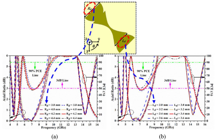
To study the effect of the design parameters on the cross and LPCP conversion performance, AR and PCE are represented in the same plot corresponding to the variation in two key parameters − the diameter of the semicircular stubs (Rd) and the width of the tapered rod (Ld). A close examination of Fig. 4(a) reveals that the AR performance in the second band is dictated by the value of Rd. Moreover, it is also responsible for improving the bandwidth of the PCE. Hence, it can be stated that this parameter helps to control the anisotropy. The value of Rd has been selected as 4.2 mm considering optimum AR and PCE bandwidths.
AR and PCE performance of the proposed polarizer with respect to the variation in (a) Rd and (b) Ld.

Furthermore, the parameter Ld performs two functions: (a) it deals with the portion of semicircular stubs joined with the tapered rod; (b) it also accounts for tapering which increases with Ld. As a result of this, it plays crucial role in determining the PCE and AR bandwidths. Hence, this parameter is included in our analysis and its effect has been portrayed in Fig. 4(b). It has been found that raising the value of Ld considerably increases PCE bandwidth while concurrently reducing AR bandwidth.
Hence, there is trade-off between PCE and AR bandwidths. The value of Ld was chosen such that the proposed polarizer shall demonstrate the characteristics of cross polarization converter and LPCP converter in considerably wide range of frequencies.
EM analysis using current distributions
To reveal the cause behind the polarization conversion mechanism, current distributions are plotted on the top and bottom surfaces of the proposed converter at the frequencies at which PCE is nearly 100% and the frequencies at which AR is minimum. During literature studies, it was found that the resonances occur due to the symmetric and antisymmetric surface current between the top patterned layer and bottom ground plane. These resonances may be electric resonance, magnetic resonance, or EM resonance subjected to the direction of currents on the top surface with respect to the ground plane at the bottom [Reference Nama, Nilotpal, Bhattacharyya and Jain11].
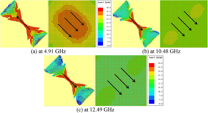
In order to study the cross polarization behavior, surface current is plotted at the frequencies where PCE is nearly 100%, i.e. 4.91, 10.48, and 12.49 GHz, as shown in Fig. 5. Figure 5(a) shows that the current direction is parallel to the top dumbbell-shaped structure and most of the current is confined in the tapered middle part. On the other hand, the current direction is found in antiparallel direction in the ground plane. This forms a circulating loop hence it resembles the presence of the magnetic resonance. However, in Fig. 5(b) and (c), the current at the top and bottom are in the same direction, which suggests electric resonance. Hence, it can be inferred that the proposed converter is exhibiting the CPC behavior due to magnetic resonance in the first band and electric resonance in the second band.
Surface current distribution of the proposed polarizer at frequencies having close to 100% PCE. (a) at 4.91 GHz, (b) at 10.48 GHz, and (c) at 12.49 GHz.

Moreover, to showcase the CP conversion mechanism in the mentioned bands, surface current distribution is plotted at 4.5, 6.05, 6.95, and 14.35 GHz (least AR frequency points), as shown in Figure 6. It is important to note that the current vectors are rotating orthogonally in the ground plane in contrasts with the above case where cross polarization took place and currents were confined in a single direction [Reference Dutta, Ghosh, Yang and Zhang17]. Figure 6(a) reveals that the currents are rotating in the counterclockwise direction, providing LP wave is incident in the –z-direction. This confirms the LHCP behavior at 4.5 GHz offered (in the first band) as illustrated by the phase difference in the “LPCP conversion” section. Similarly, Fig. 6(b–d) represents the sense of rotation as right-handed due to the clockwise rotation of surface currents. Hence it is concluded that the proposed structure converts LP wave to LHCP wave in first band while converts into the RHCP wave for rest two higher bands.
Surface current distribution of the proposed polarizer at the frequencies with least axial ratio. (a) at 4.50 GHz, (b) at 6.05 GHz, (c) at 6.95 GHz, (d) at 14.34 GHz.

Experimental results and discussion
Proposed polarizer has been fabricated on a FR4 glass epoxy substrate of volume 300 × 300 × 3.2 mm3 to realize the polarization conversion surface and accommodates 900 (30 × 30) unit-cells of the suggested structure. Figure 7(a) shows a snapshot of the constructed prototype along with a macroscopic view and Fig. 7(b) depicts the experimental configuration used to measure the polarization converter’s intended performance. This setup is customized according to the requirement of measuring the reflection characteristics of the polarizer. To do this, first, both the horn antennas are oriented in the same polarization state to record the reflected co-polarized waves (ryy). However, to measure the cross-polarized reflected waves (rxy), the receiving horn antenna is rotated by 90°. It is important to note that the prototype is placed at a distance of 1 m (>2D2/λ) from the horn antennas to reduce the near-field effects and simultaneously ensure the incidence of plane wave on the metasurface. Here, D is the maximum aperture of the horn antennas and λ is the largest free-space wavelength.
Photograph of the (a) implemented polarization converter surface and (b) Customized anechoic chamber setup for reflection magnitude and phase measurement.

Figure 8(a) shows the measured results of reflection coefficient along with simulated ones to show the CPC capability. Measured results suggest that the proposed polarizer is capable to alter the polarization state from y-to-x polarization and vice versa over 4.72−5.05 and 8.92−13.55 GHz. This corresponds to the fractional bandwidths (FBWs) of 6.77% and 41.22% considering center frequency of 4.88 and 11.23 GHz, respectively. To further verify the CPC behavior, the simulated and measured PCE is also plotted in Fig. 8(b). It can be monitored that the proposed converter is successful in maintaining the PCE above 90% over the above-mentioned bands. However, minor discrepancies can be observed between simulated and experimental results which are subjected to the measurement inaccuracy in the placement of the polarizer sheet.
Comparison of simulated and measured (a) reflection coefficients of co- and cross-polarized waves and (b) polarization conversion efficiency.

Subsequently, the prototype’s behavior in terms of LPCP conversion is analyzed. As mentioned in the “Unit cell geometry and principle of polarization conversion” section, the co- and cross-polarized reflected waves’ reflection phases and magnitudes are also required for analyzing this behavior. Figure 9(a) demonstrates the experimentally obtained magnitude ratio of ryy to rxy and the phase difference between them. Maximum tolerance of merely 13° is monitored after careful examination in reflection phases. Using relation (2) and (3), the AR is then computed and plotted in Fig. 9(b). The data indicate that there is excellent agreement between the simulated and measured results due to the lowest tolerance level in phases and magnitude. These reliable results are the resultant of armored phase stable cables constructed for phase measurement purpose which ensures least level of tolerances in simulated and measure results. Finally, measured results suggest that the proposed converter is exhibiting LPCP performance in the three bands ranging from 4.12 to 4.55, 5.16 to 8.42, and 13.85 to 15.20 GHz which is equivalent to FBW of 9.81%, 48.01%, and 9.35% considering center frequency of 4.38, 6.79, and 14.44 GHz, respectively.
(a) Measured magnitude ratio of the reflectance and reflection phase difference of co- and cross-polarized waves, and (b) Measured and simulated axial ratio of the proposed polarization converter.

It is significant to observe from Figs. 8 and 9 that there is no overlap in the specified frequency bands corresponding to its CPC and LPCP conversion performance. Thus, the experimental results validate that the proposed converter can effectively convert the 4–16 GHz frequency range of linear polarization to either its cross counterpart or CP waves. This renders the suggested converter extremely effective.
In order to show the novelity and contribution of the proposed work, a qualitative comparison with the latest relevant works in the literature has been presented in Table 1. It is worth mentioning that all the converters included in this table are offering CPC and LPCP behavior concurrently in different bands and are based on the reflective metasurfaces for fair comparison. Moreover, these works are compared with respect to the types of substrate, electrical size, thickness of the unit cell, number of bands, and their FBWs in terms of AR and PCE. This table suggests that the low cost FR4 substrate is a better choice to exhibit hybrid polarization conversion characteristics. It also demonstrates a study representing efficiency of the reflective surfaces to offer polarization conversion behavior which is investigated for the first time to the author’s best knowledge. This study suggests that how effective a polarizer is capable to convert the polarization in either states over maximum available bandwidth such that it can be utilized efficiently. It has been noted that in certain bands, the majority of polarizers documented in the literature fail to change the polarization state. These bands can be identified as null operation zone (NOZ). It has been calculated in the table by considering the PCE and AR bandwidths. With the exception of paper [Reference Wahidi, Khan, Tahir and Rmili24], it is perceived that all of the polarizers under comparison underutilize their bandwidths and do not change the polarization state with respect to its CPC or LPCP. However, this work [Reference Wahidi, Khan, Tahir and Rmili24] is hindered by its large electrical size. Conversely, the suggested polarizer exhibits nearly no null operation region; that is, it functions as a CPC or LPCP converter within the 4–16 GHz frequency range. In addition, it offers largest AR and PCE bandwidths among all the compared works. The proposed polarizer’s electrical size is also small and comparable to previous designs, making it compatible with antennas to change the polarization state of EM waves.
Comparison of different figure of merits with the recent reflective type hybrid polarization converters

λ L, λ W, and λ 0= length, width, and thickness, respectively, of the unit cells in terms of free-space wavelength calculated at the lower frequency of operation.
a Operating band is not mentioned in the paper.
Conclusion
A modified dumbbell-shaped reflective type polarization converter with broadband LPCP and CPC characteristics is designed, developed and tested in this paper. Measured results demonstrate that the proposed converter is exhibiting the CPC characteristics in 4.72−5.05 and 8.92−13.55 GHz bands with PCE above 90%. It is also capable to convert LP waves to CP waves over 4.12−4.55, 5.16−8.42 GHz, and 13.85−15.20 GHz with AR well below 3 dB, due to the minimum tolerance in phase difference between co- and cross-polarized reflected waves. Measured results follow the simulated patterns due to its simplified structure. Novelty of the proposed converter corresponds to the fact that it has almost zero NOZ in the frequency range of 4−16 GHz which is rarely been observed in the previously reported literatures. Moreover, its ultra-thin, miniaturized profile and multifunctional characteristics in five distinct bands suggest that it can be adopted for any defense, satellite, or on-antenna applications over the wide range of frequencies.
Acknowledgements
This work was supported by Directorate of Research Innovation and Development, Jaypee University System, Jaypee Institute of Information Technology, Noida (Grant Number: DRID/COE/15/2023).
Competing interests
The authors declare that they have no known competing financial interests or personal relationships that could have appeared to influence the work reported in this paper.

Dr. Ashish Gupta is currently working as an assistant professor in Jaypee Institute of Information Technology, Noida. He has done his Ph.D. in RF and Microwave Engineering from Department of Electronics Engineering, Indian Institute of Technology (Indian School of Mines) Dhanbad in 2017. He did his M. Tech. from Shri Govindram Seksaria Institute of Technology and Science, Indore, in 2010. He is the senior member of IEEE society since 2020 and the member of APS society since 2019. He got fellowship from MHRD Govt. of India during his M.Tech. tenure. He has received National Instruments Students Travel Fellowship at IIT Bombay, India. He was also offered an international travel grant sponsored by ISM alumni association for presenting a research paper in Vancouver, Canada. He has published more than 30 articles in refereed journals of repute, 25 papers in the renowned conferences and multiple book chapters in the relevant area. Dr. Gupta is serving as reviewer in multiple journals of repute and several conferences and in the member of the editorial board in certain journals. His current research interests involve metamaterial antennas, microstrip antennas, filtering antennas, metamaterial-inspired microwave absorbers, microwave polarizers, and microwave filters.

Dr. Raghvenda Kumar Singh received his Ph.D. degree in RF and Microwave Engineering from Jaypee Institute of Information Technology (JIIT), Noida, in 2023. He did M.Tech. in RF and Microwave Engineering from Indian Institute of Technology, Roorkee, from 2012 to 2014, where he got fellowship from MHRD Govt. of India. He worked as an Assistant Professor in Department of ECE, Teerthanker Mahaveer University, Moradabad, from July 2014 to January 2017. Since January 2017, he is working as an Assistant Professor at JIIT, Noida. He is a member of IEEE, IEEE Young Professional UP Section Team, IEEE AP-S, and IEEE MTT-S. Also, he is acting as reviewer of reputed journals like Wireless Personal Communications, International Journal of Antennas and Propagation, and Microwave and Optical Technology Letters. He has published more than 20 papers in reputed journals and conference proceedings. His research interests include metasurface, metamaterial antenna, microwave absorber, polarization converter, and terahertz sensors.

Akshat Sinha is currently pursuing his B.Tech degree in Electronics and Communication Engineering from Jaypee Institute of Information Technology, Noida. He is working as an associate business quality analyst intern at Rxlogix Sector 125, Noida. He has completed his summer internship at Goldilocks Tech Solution Pvt Ltd. Also, his research interests include metasurfaces, metamaterial antenna, polarization converter, and inductive loaded antenna.

Swarnim Pathak is currently pursuing his B.Tech degree in Electronics and Communication Engineering from Jaypee Institute of Information Technology, Noida. He has completed his summer internship at Glorious Insight Pvt Ltd Sector 136, Noida. His research interests include metasurface, microwave polarizers, and inductive loaded patch antenna.

Preet Singh Sodhi is currently pursuing his B. Tech. degree in Electronics and Communication Engineering from Jaypee Institute of Information Technology, Noida. He has completed his summer internship at Samvardhana Motherson International Limited. His research interests include metasurface-based polarization converter, and inductive loaded antenna.