NOMENCLATURE
- a
torque offset or lift curve slope
- c
blade chord (= 2 b)
- Cw
weight coefficient
- e1, e2
root offset
- {FAD}
aerodynamic force vector
- [M]
mass matrix or apparent mass matrix in inflow model
- [MC]
Coriolis damping matrix
- Nb
number of blades in main rotor
- OH
hub centre
- R
main rotor blade radius
- βd
blade pre-droop angle
- βp
blade pre-cone angle
- βs
blade pre-sweep angle
- γ
lock number
- Λa
tip-anhedral angle
- Λs
tip-sweep angle
- η, ζ
blade cross-sectional principal axes coordinates
- θG
geometric pitch angle of rotor blade
- θI
control pitch angle of rotor
- θ0
mean value of pitch angle or main rotor collective pitch angle
- θ1c, θ1s
cyclic pitch angles for main rotor
- ρ
density of air
- σ
main rotor solidity ratio
- ψ
azimuthal angle or non-dimensional time, Ωt
1.0 INTRODUCTION
The structural dynamics and aeroelastic characteristics of a rotor blade influence the performance of the helicopter in terms of loads, vibrations and handling qualities. These characteristics are sensitive to variations in blade geometric parameters(1). There have been several studies reported in open literature which aimed to develop an understanding of the role played by these parameters in rotor loads and vibrations.
While it is known that pre-twist improves aerodynamic performance of the rotor blade, there have been differing observations on the influence of pre-twist on vibratory loads. In Reference BlackwellRef. 2, it is shown that there is little sensitivity of blade vibration to pre-twist, while Reference HeRefs 3 and Reference Laxman, Venkatesan and Byun4 deduce that structural coupling from blade pre-twist significantly influences blade response and loads. In Reference Laxman, Venkatesan and ByunRef. 4, it was also concluded that the magnitudes of oscillatory root and hub loads are significantly altered by variations in hinge- and root-offsets. In Reference GötzfriedRef. 5, it was shown that a 2.5° pre-cone angle resulted in reduced lead-lag bending loads as compared to those for a 2.5° droop.
Concentrated masses are added to the rotor blade for balancing. Reference HeRef. 3 showed that mass tuning is also effective in minimising vibratory hub loads. In Reference Pritchard, Adelman, Walsh and WilburRef. 6, an optimisation procedure was developed to systematically place tuning masses along a rotor blade span to minimise vibratory loads. Reference Yoo, Seo and HuhRef. 7 concluded that the magnitude and location of the concentrated mass significantly influence the modal characteristics of the rotating beam.
Tip-sweep and tip-anhedral are other important parameters used to improve rotor aerodynamic performance. In a recent study(8), the natural frequencies of a rotating beam with tip-sweep and tip-anhedral were obtained using a structural dynamic model and correlated with experimental data. With regards to vibration, both experimental(2) and analytical results(9,10) have shown reduction in 4/rev hub loads in forward flight with addition of tip-sweep. The study in Reference Kim and ChopraRef. 11 concluded that tip-sweep reduces flap and torsional oscillatory responses while tip-anhedral has considerable influence on flap dynamics.
In this article, the effects of blade geometry parameters are studied using an aeroelastic formulation of a generic rotor blade with non-linear structural and unsteady aerodynamic models. The objectives of this article are to determine:
(i) the effects of blade geometry parameters on rotating blade natural frequencies, and identify the parameters influencing the structural coupling in mode shapes
(ii) the effects of tip-sweep and tip-anhedral on loads at the blade root and also at the junction between the tip section and straight portion of the blade
2.0 BLADE STRUCTURAL MODEL
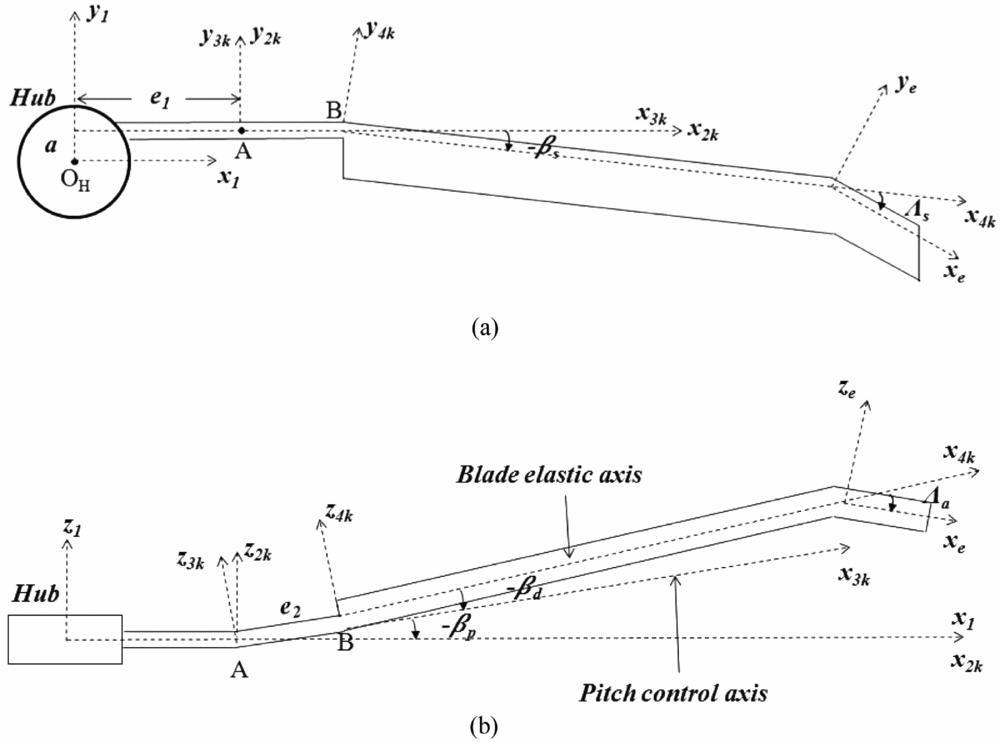
The rotor structural and aerodynamic models are described in detail in Reference Kumar and VenkatesanRef. 12. For this work, a general geometry has been assumed for the rotor blade. Non-linearities in structural modelling and in aerodynamic modelling due to dynamic stall have been considered. An elastic rotating beam with constant angular velocity and features like blade root offset, torque offset, pre-twist, pre-cone, pre-droop, pre-sweep, tip-sweep and tip-anhedral was considered. The option of adding concentrated masses meant for blade tracking and balancing was also included. Figures 1(a) and 1(b) show the orthogonal co-ordinate systems describing the geometry of the rotating blade.
Blade co-ordinate systems: (a) blade top view and (b) blade front view.

2.1 Co-ordinate transformations
In this section, the key co-ordinate transformations used in deriving the equations of motion of the rotor blade and involving the geometric features being studied are described. The relation between two orthogonal systems Xi, Yi, Zi and Xj, Yj, Zj with êxi, êyi and êzi and êxj, êyj and êzj as unit vectors along the respective axes can be written as:
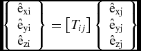 $$\begin{equation}
\left\{ {\ \begin{array}{*{20}{c}} {{{\rm{\hat{e} }}_{{\rm{xi}}}}}\\ {{{\rm{\hat{e} }}_{{\rm{yi}}}}}\\ {{{\rm{\hat{e} }}_{{\rm{zi}}}}} \end{array}\ } \right\} = \left[{{T_{ij}}} \right]\left\{ {\ \begin{array}{*{20}{c}} {{{\rm{\hat{e} }}_{{\rm{xj}}}}}\\ {{{\rm{\hat{e} }}_{{\rm{yj}}}}}\\ {{{\rm{\hat{e} }}_{{\rm{zj}}}}} \end{array}\ } \right\}
\end{equation}$$
where the transformation matrix [Tij] can be obtained using the Euler angles required to rotate the j-system so as to make it parallel to the i-system.
The angle between the 3K and 2K systems is -βp (Fig. 1(b)). Here, K refers to the kth blade. Applying the small-angle approximation (sin βp ≈ βp and cos βp ≈ 1), the transformation relation between these two systems is given by:
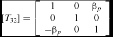 $$\begin{equation}
\left[{{T_{32}}} \right] = \left[{\ \begin{array}{*{20}{c}} 1&\quad 0&\quad {\beta_{p}}\\ 0&\quad 1&\quad 0\\ {{-\beta_p}}&\quad 0&\quad 1 \end{array}\ } \right]
\end{equation}$$
The 4K-system is obtained by (i) translating the origin of the 3K-system by a distance ‘e2’ along êx3k, (ii) then rotating the system by an angle -βs (pre-sweep angle) about z3k axis, (iii) then rotating the system by an angle -βd (pre-droop angle) about y3k axis, and finally, (iv) rotating the system by an angle θI (pitch input) about x3k axis. The rotation sequence for obtaining the 4K system from the 3K system is a space-fixed rotation sequence(13), as all the rotations are about the 3K-axes. The transformation matrix, after applying small-angle approximation for angles βs and βd, is given by:
 $$\begin{equation}
\left[ {{T_{43}}} \right] = \left[ {\begin{array}{*{20}{c}} 1&\quad { - \left( {\beta_s{\rm{cos}}{\theta _I}{ + \beta_d}{\rm{sin}}{\theta _I}} \right)}&\quad {\left( {\beta_d{\rm{cos}}{\theta _I}{ - \beta_s}{\rm{sin}}{\theta _I}} \right)}\\ {\beta_s}&\quad {{\rm{cos}}{\theta _I}}&\quad {{\rm{sin}}{\theta _I}}\\ {{ - \beta_d}}&\quad { - {\rm{sin}}{\theta _I}}&\quad {{\rm{cos}}{\theta _I}} \end{array}} \right]
\end{equation}$$
The transformation matrix between the e- and the 4K systems for the swept-tip element is given by:
 $$\begin{equation}
{\left[ {{T_{e4}}} \right]_t} = \left[ {\ \begin{array}{*{20}{c}} {{\rm{cos}}{\Lambda _s}{\rm{cos}}{\Lambda _a}}&\quad { - {\rm{sin}}{\Lambda _s}}&\quad {{\rm{cos}}{\Lambda _s}{\rm{sin}}{\Lambda _a}}\\ {{\rm{sin}}{\Lambda _s}{\rm{cos}}{\Lambda _a}}&\quad {{\rm{cos}}{\Lambda _s}}&\quad {{\rm{sin}}{\Lambda _s}{\rm{sin}}{\Lambda _a}}\\ { - {\rm{sin}}{\Lambda _a}}&\quad 0&\quad {{\rm{cos}}{\Lambda _a}} \end{array}\ } \right]
\end{equation}$$
where Λs is the blade tip sweep angle (positive for backward sweep) and Λa is the blade tip anhedral/dihedral angle (positive upward).
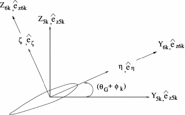
The 5K-system is the cross-sectional co-ordinate system of the kth blade. The 6K-system is obtained by rotating the 5K-system about êx5k by an angle (ϕk + θG), where θG is the geometric twist angle of the cross-section and ϕk is the elastic twist. The transformation relation between the 5K- and the 6K-systems (Fig. 2) is given by:
 $$\begin{equation}
\left[ {{T_{65}}} \right] = \left[ {\ \begin{array}{*{20}{c}} 1&\quad 0&\quad 0\\ 0&\quad {{\rm{cos}}\left( {{\phi _k} + {\theta _G}} \right)}&\quad {{\rm{sin}}\left( {{\phi _k} + {\theta _G}} \right)}\\ 0&\quad { - {\rm{sin}}\left( {{\phi _k} + {\theta _G}} \right)}&\quad {{\rm{cos}}\left( {{\phi _k} + {\theta _G}} \right)} \end{array}\ } \right]
\end{equation}$$
Cross-sectional principal co-ordinate system.
2.2 Equations of motion
The blade structural formulation follows the approach in Reference Yuan, Venkatesan and FriedmannRef. 14. The non-linear equations of motion were derived for each beam element using Hamilton's principle. The equations are based on a moderate deflection theory and account for: arbitrary cross-sectional shape, pre-twist, generally anisotropic material behaviour, transverse shears and out-of-plane warping. Strain-displacement expressions are derived from Green's strain.
The blade is modelled by a series of straight beam finite elements along the elastic axis of the blade. Each beam element consists of two end nodes and one internal node at its mid-point, resulting in 14 degrees of freedom representing 4 lag, 4 flap, 3 torsional and 3 axial motion variables. Cubic Hermite interpolation polynomials are used for the bending displacement, while quadratic Lagrangian interpolation polynomials are used for torsional rotation and axial deflections.
2.3 Local-to-global co-ordinate transformation
Special care needs to be taken during assembly of the tip element matrices when tip-sweep or tip-anhedral is present. The local-to-global co-ordinate transformation for the tip element with sweep or anhedral can be written in the form
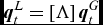 $$\begin{equation}
\boldsymbol{q}_t^L = \left[ \Lambda \right]\boldsymbol{q}_t^G
\end{equation}$$
where q represents the vector of unknown nodal degrees of freedom and the subscript t denotes quantities associated with the tip element; the superscripts L and G denote the local (e) and global (4K) co-ordinate system, respectively. The transformation matrix, [Λ], is derived with the condition that the angular relationship between the tip-sweep (or tip-anhedral) and the straight portion of the blade at the junction is preserved after deformation(15). The elements of the local-to-global transformation matrix [Λ] for the tip element are given in the Appendix.
3.0 COMPLETE AEROELASTIC EQUATION FOR THE ROTOR BLADE
3.1 Structural dynamics analysis
The first step in the aeroelastic response study is to solve the linear, undamped structural dynamics model in the finite element domain to obtain the natural frequencies and the corresponding mode shapes of the rotating blade(16). The governing equation for the ith finite element is
 $$\begin{equation}
\left[ {{M_i}} \right] \left \{ {{{\mathrm{\ddot q}}_\mathrm{i}}} \right \} + \left[ {{K_i}} \right] \left \{ {{\mathrm{q}_\mathrm{i}}} \right \} = 0
\end{equation}$$
where [Mi] represents the mass matrix of the ith element.
For cases with tip-sweep/anhedral, the governing equation for the tip element is given by
 $$\begin{equation}
{\left[ \Lambda \right]^T}\left[ {{M_t}} \right]\left[ \Lambda \right]\left\{ {{{\mathrm{\ddot q}}_\mathrm{t}}} \right\} + {\left[ \Lambda \right]^T}\left[ {{K_t}} \right]\left[ \Lambda \right]\left\{ {{\mathrm{q}_\mathrm{t}}} \right\} = 0
\end{equation}$$
The element matrices are assembled to form the global finite element model for the rotor blade.
3.2 Aerodynamic model
The approach used for aerodynamic modelling has been described in detail in Reference Kumar and VenkatesanRefs 12 and Reference Laxman and Venkatesan17. The aerodynamic model involves the evaluation of inflow (Peters-He model(18)), at various locations on the rotor disc and the evaluation of sectional aerodynamic loads (modified ONERA dynamic stall model(19)), on the rotor blade.
3.3 Aeroelastic equation
The global aeroelastic equation for the whole blade is obtained by assembling the elemental matrices from the kinetic and strain energy contributions,
 $$\begin{equation}
\left[ M \right]\left\{ {\boldsymbol{\ddot q}} \right\} + \left[ C \right]\left\{ {\boldsymbol{\dot q}} \right\} + \left[ K \right]\left\{ \boldsymbol{q} \right\} = \left\{ {{F_{AD}}} \right\}
\end{equation}$$
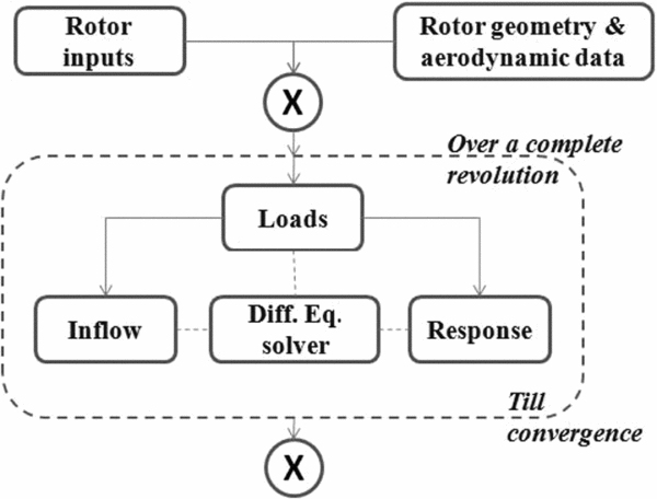
where {FAD} is the aerodynamic force contribution. To reduce the number of degrees of freedom of the problem, modal co-ordinate transformation is performed on the aeroelastic equation. Eight modes comprising two lag, four flap, one torsion and one axial modes were used in the modal transformation. Solution of the non-linear aeroelastic equation of the main rotor involves successively calculating the inflow, rotor loads and the resulting response for a small time step. The time is then incremented and the calculation process is repeated until the converged periodic solution for a complete revolution is obtained. The flowchart of the solution procedure is shown in Fig. 3. The GSL math library(20) was used in the C++ program used to implement the algorithm. The models described in the previous sections and the solution procedure for loads and response calculations were validated for structural dynamics and whirl tower analysis in Reference Kumar and VenkatesanRef. 12.
Flowchart for whirl tower analysis.
4.0 EFFECTS OF BLADE CONFIGURATION PARAMETERS ON STRUCTURAL DYNAMICS
A parametric study was undertaken to study the effect of each of the various geometric parameters on the structural dynamic characteristics of the rotor blade. The baseline blade is an untwisted, straight blade with all geometric parameters (hinge-offset, torque-offset, pre-droop, pre-cone, pre-sweep, tip-sweep and tip-anhedral) set equal to zero. Each case consisted of setting a finite value to one geometric parameter at a time in the baseline blade. Blade mass distribution, m0, was taken to be 8.45 kg/m and non-dimensional chord (c/R) was taken as 0.0757. The beam is clamped at the root.
4.1 Parametric study–results
4.1.1 Natural frequencies
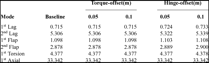
Table 1 shows the effects of torque- and hinge-offsets on the natural frequencies of the blade. Torque-offset has no effect while the hinge-offset increases the bending frequencies. The torsional and axial frequencies are hardly affected.
Effect of torque- and hinge- offsets on natural frequencies (@ 314 RPM)
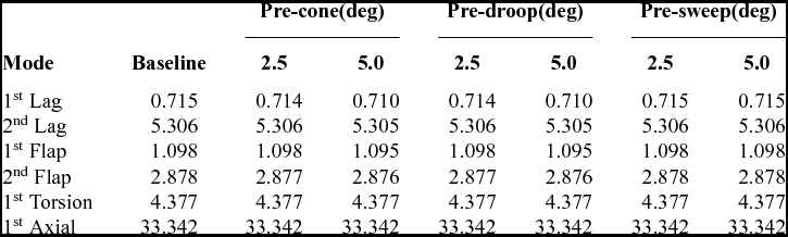
Table 2 shows the effect of pre-cone, pre-droop and pre-sweep on the natural frequencies. Pre-cone is the inclination of the pitch-change bearing with respect to the plane of rotation, while pre-droop is the inclination of the blade outboard of the pitch-change bearing. Both pre-cone and pre-droop slightly reduce the frequencies of the lower bending modes. The higher bending modes, torsional mode and axial mode, are hardly affected. Pre-droop has identical behaviour as pre-cone when both pitch input and pre-sweep angles are zero. This can be seen from their respective co-ordinate transformation matrices (Equations (2) and (3)). Pre-sweep does not have any effect on the frequencies.
Effect of pre-cone, pre-droop, pre-sweep on natural frequencies (@ 314 RPM)
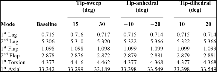
Table 3 shows the effect of tip-geometry. The outboard 10% of the rotor blade is given a sweep or anhedral/dihedral angle. Tip-sweep is seen to increase the lag frequencies while flap frequencies are decreased. Tip-sweep effect is mostly seen in the torsional mode, the frequency of which is increased, while axial frequencies decrease with increase in tip-sweep. The reason for the increase in torsional frequency is the increase in torsional stiffness of the rotor blade due to the centrifugal force of the swept-tip. In the case of tip-anhedral (downward angle) and tip-dihedral (upward angle), both of which show the same effect, the bending (both lag and flap) and axial frequencies increase slightly, while the torsional frequency decreases with increase in tip-anhedral/dihedral.
Effect of tip-sweep, tip-anhedral, tip-dihedral on natural frequencies (@ 314 RPM)
Concentrated masses are used in rotor blades for balancing and for reducing rotor vibration. They can also be in the form of sensors attached to the blade during experiments. Concentrated masses increase the modal mass of the rotor blade and also increase the centrifugal stiffening effect. Depending on the magnitude and the location of the mass, one of these effects is more dominant. When the modal mass increase is more dominant than the centrifugal stiffening effect, the natural frequency is reduced and vice-versa.
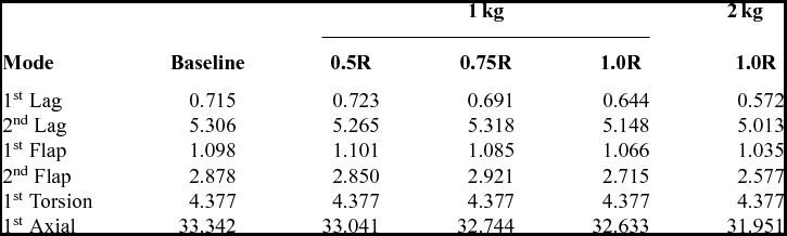
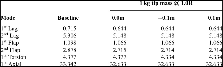
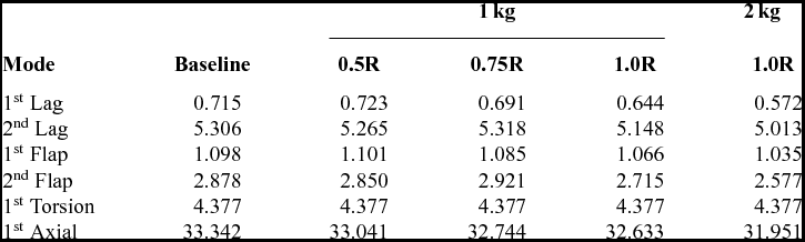
The effect of spanwise location and the effect of magnitude of concentrated mass is shown in Table 4. In general, as the spanwise location of the concentrated mass increases radially, the bending and axial frequencies decrease. The torsion frequency is left untouched as the mass is placed on the elastic axis. Increasing the magnitude of the concentrated mass (1 kg to 2 kg) reduces the bending and axial frequencies but does not affect the torsion mode. Table 5 shows the effect of chordwise location (from the elastic axis) of a tip mass. The torsional frequency reduces when the mass is moved away from the elastic axis. None of the other modes are affected.
Effects of concentrated mass radial location and magnitude (@ 314 RPM)
Effect of concentrated mass chordwise location (@ 314 RPM)
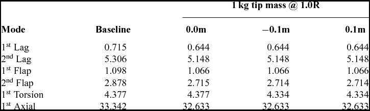
*Concentrated mass placed on elastic axis.
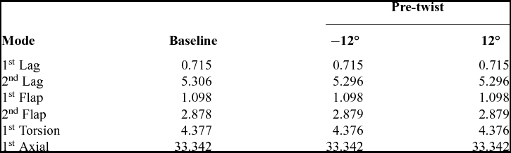
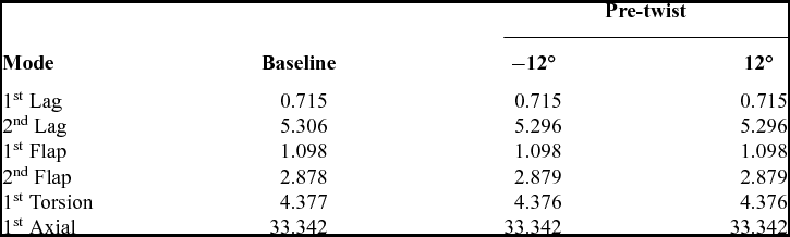
The effect of pre-twist on the blade is shown in Table 6. The frequencies of the baseline untwisted blade are compared with those of blades having pre-twist of −12° and 12° such that the geometric twists at the section at 0.7R are zero. Airfoil portion of the blade begins at 0.25R and, hence, this is where pre-twist starts. The table shows that only the higher-bending (lag and flap) frequencies are slightly affected due to the pre-twist. There is hardly any change in the frequency of the torsional mode. Pre-twist does not have much effect on the natural frequencies because the neck region of the blade (<0.25R) with less stiffness than the airfoil region primarily determines the structural dynamics characteristics.
Effect of pre-twist (@ 314 RPM)
Summarising from the results above, of all the geometric parameters, hinge-offset affects the bending (lag and flap) frequencies the most without affecting the torsion frequency. Tip-sweep affects torsion frequency the most with least effect on the bending frequencies. Torsion frequency can also be altered without affecting the bending frequencies by placing concentrated masses with a chord-offset.
4.1.2 Mode shapes
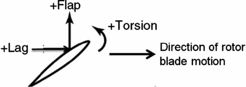
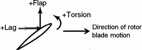
Next, the effects of the geometric parameters on mode shapes are studied. Changes in mode shapes alter the modal generalised forces. In this section, only those cases which show some effect on the mode shapes have been plotted. Only the first lag and first flap modes are plotted. The sign convention for the mode shapes are shown in Fig. 4. It is to be noted that pitch-up deformation is taken as positive. Figures 5–9 show the first lag and first flap modes along with the corresponding coupled torsion or axial deformation for the cases of pre-cone, tip-sweep, tip-anhedral and pre-twist. The other geometric parameters were found to have negligible influence as far as the mode shapes are concerned.
Positive directions for the airfoil degrees of freedom.
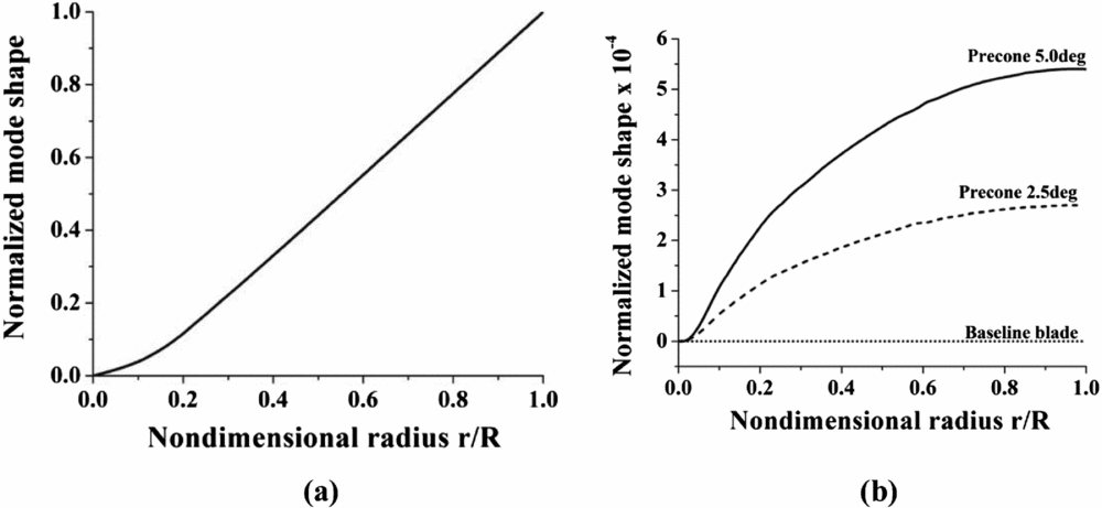
Effect of pre-cone on 1st lag mode. (a) 1st Lag. (b) Torsion participation in 1st Lag.
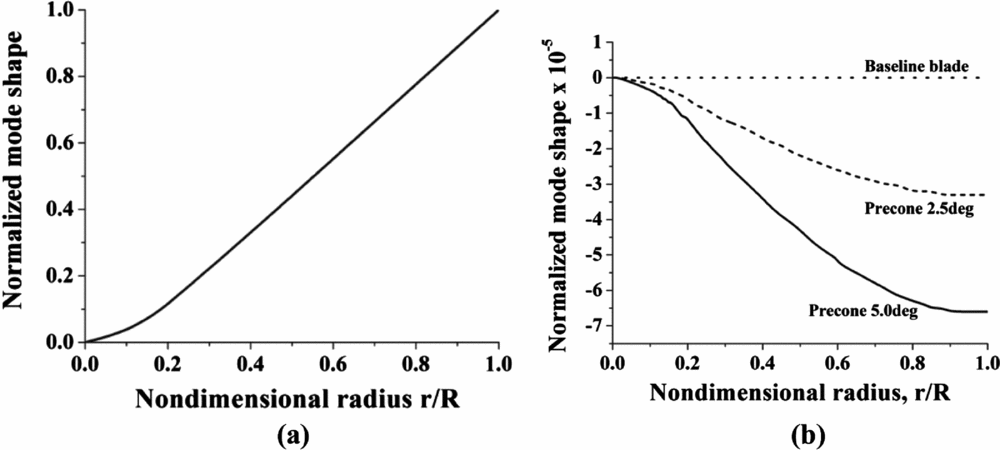
Effect of pre-cone on 1st flap mode. (a) 1st Flap (b) Axial participation in 1st Flap.
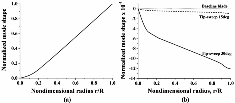
Effect of tip-sweep on mode shapes. (a) 1st Flap (b) Torsion participation in 1st Flap.
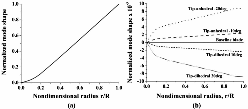
Effect of Tip-anhedral/dihedral on mode shapes. (a) 1st Lag (b) Torsion participation in 1st Lag.
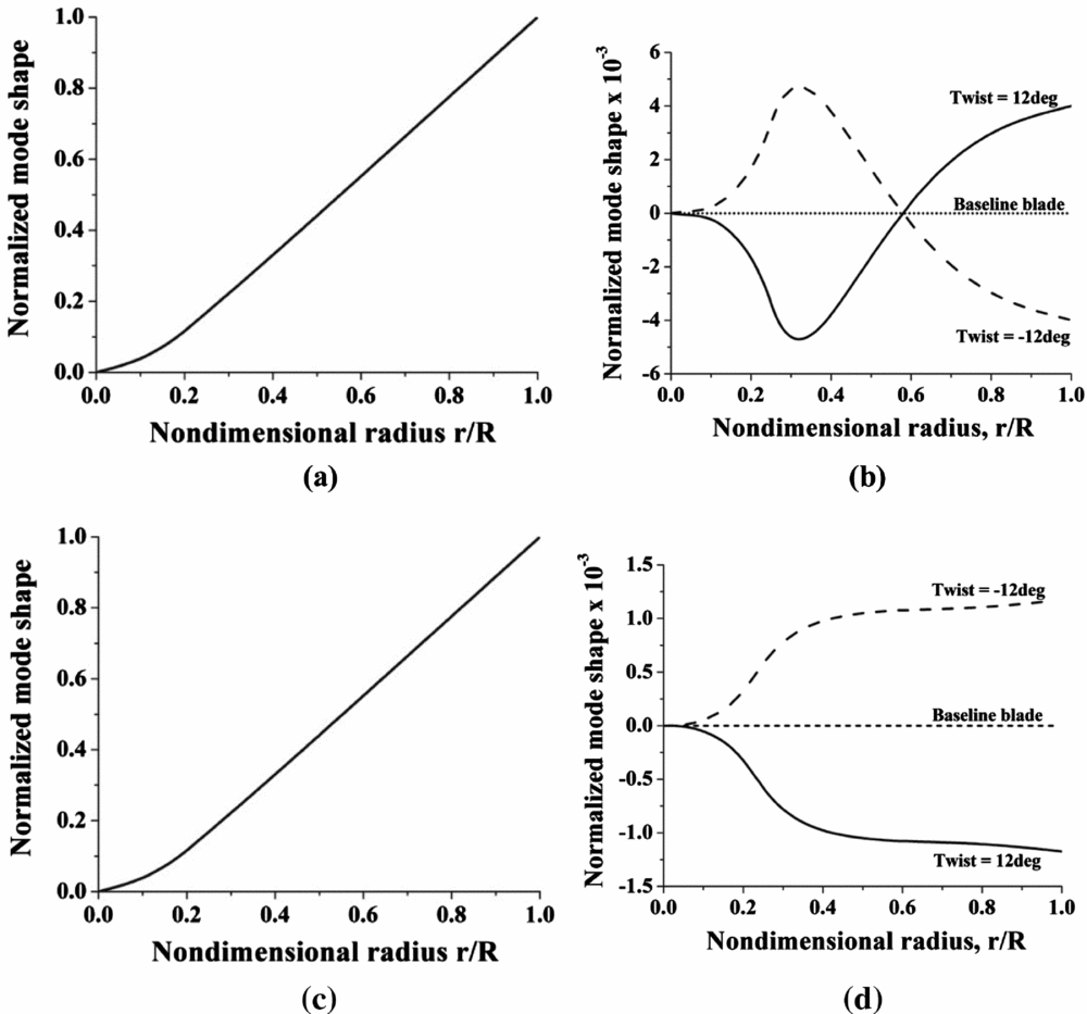
Effect of pre-twist on mode shapes. (a) 1st Lag (b) Flap participation in 1st Lag. (c) 1st Flap (d) Lag participation in 1st Flap.
Figure 5(a) shows the first lag mode for the baseline blade. It was observed that there is no change in the mode shape with inclusion of pre-cone angle. Hence, for legibility, only the baseline blade mode shape has been plotted here. Figure 5(b) shows the participation of torsion deformation in this mode. It can be seen that while the lag mode shape is not significantly affected by pre-cone, the coupled torsion deformations have been substantially affected. There is an increasing pitch-up deformation with increase in pre-cone. Similarly, Fig. 6(a) shows the first flap mode of the baseline blade. There is no change in this mode with increase in pre-cone angle. The first flap mode was found to be coupled with axial mode and this can be seen in Fig. 6(b). The participation of the axial deformation in this mode is observed to be increasing with increase in the pre-cone angle.
Figures 7 and 8 show the effect of tip-sweep and tip-anhedral/dihedral on the mode shapes. Tip-sweep was found to induce flap-torsion coupling, while tip-anhedral/dihedral was found to induce lag-torsion coupling. This can be explained by the fact that there is an in-plane offset of the centre of gravity at the tip in the case of tip-sweep which causes a pitching moment about the elastic axis during flap motion. Similarly, there is an out-of-plane offset of the centre of gravity at the tip in the case of tip-anhedral which causes a pitching moment about the elastic axis during lead-lag motion. The torsion participation in the first flap mode with increase in tip-sweep is shown in Fig. 7(b). There is no effect of tip-sweep on the flap mode (Fig. 7(a)) itself and hence, only the baseline blade flap mode is shown. Only the coupled torsion deformation is affected by tip-sweep, and it is seen that there is an increasingly pitch-down deformation with increase in sweep. Similarly, in Fig. 8(b), it is seen that the coupled torsion deformation in first lag is pitch-up for tip-anhedral case and pitch-down for tip-dihedral case. The torsion participation is seen to increase with increase in tip-anhedral/dihedral. There is no effect of tip-anhedral on the lag mode (Fig. 8(a)).
Pre-twist in rotor blades causes coupling of flap and lead-lag motion. This can be seen from Fig. 9 where the mode shapes of the baseline untwisted blade are compared with those of blades having pre-twist of −12° and 12°, such that the geometric pitch angle at the section at 0.7R are zero. Figure 9(b) shows flap participation in first lag mode and Fig. 9(d) shows lag participation in the first flap mode. The positive and negative twists produce opposite effects in the coupled motion as seen in the figures. However, there is no effect of pre-twist on the bending modes themselves (Fig. 9(a) for first lag and Fig. 9(c) for first flap). There is no change in the mode shape of the torsional mode due to the blade pre-twist and hence, the torsional mode has not been plotted.
5.0 EFFECTS OF BLADE CONFIGURATION PARAMETERS ON WHIRL TOWER LOADS
5.1 Effects of collective input
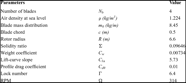
In a whirl tower, the rotor is mounted above the ground on a vertical stand with a motor with facility to change rotor collective and cyclic pitch input. The general effects of the blade configuration parameters on the whirl tower loads with variation in collective angle have been studied in Reference Kumar and VenkatesanRef. 12. The geometry of the rotor of the whirl tower used for the analysis is given in Table 7. It was seen in this study that pre-cone and pre-droop reduce root flap bending stresses at higher collective angles. Similarly, torque offset was seen to reduce the root lead-lag moment. The other parameters were found not to have significant effects on the root moments and tip displacements. However, tip geometry effects were not considered in this reference.
Rotor data
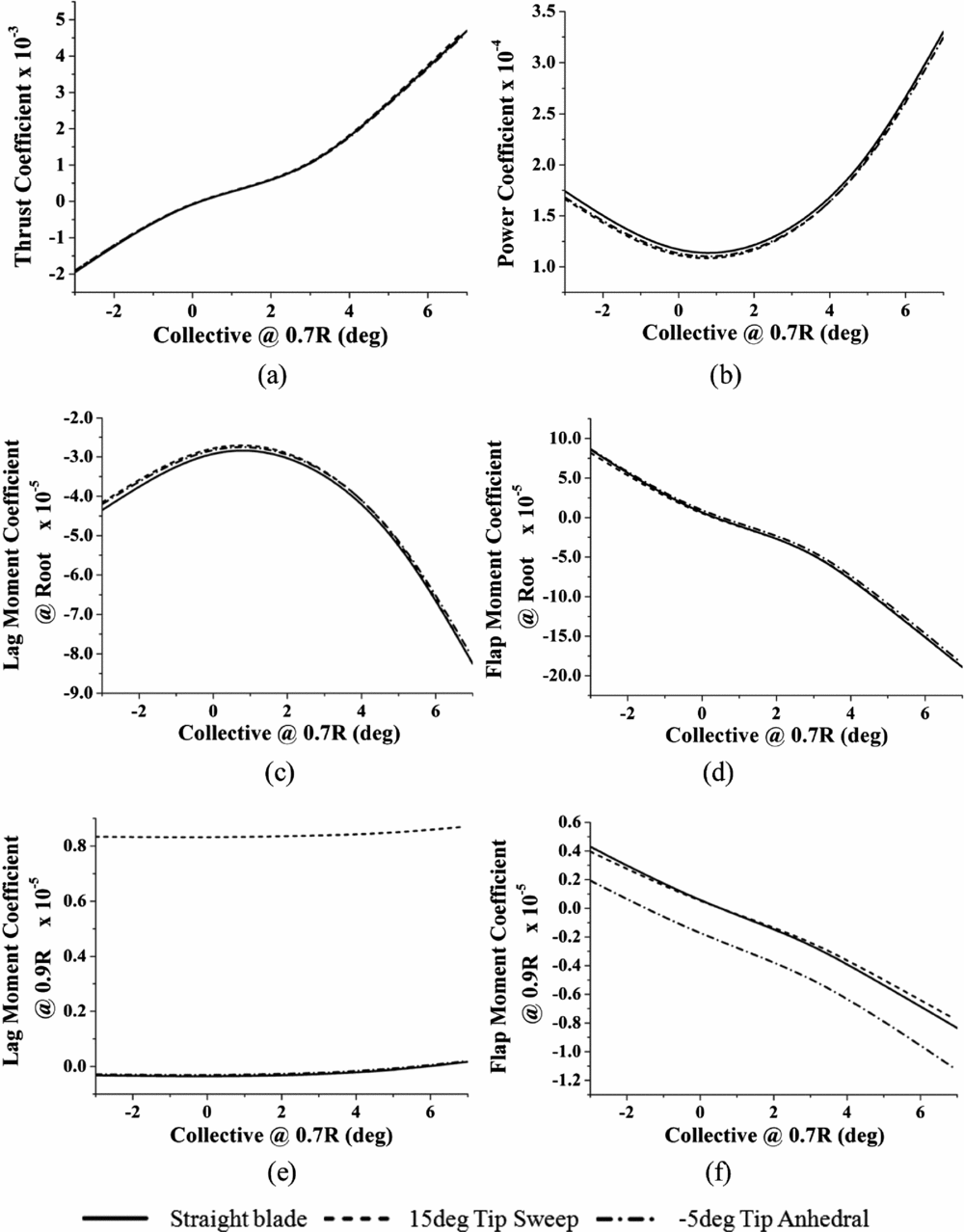
Figure 10 shows the effects of tip-sweep and tip-anhedral with change only in collective angle. It is seen that these two parameters do not have much effect on thrust and power coefficients (Figs 10(a), 10(b)), and the root bending moments (Figs 10(c), 10(d)). However, it is interesting to note that tip-sweep induces a large increase in the lag moment at 0.9R which is its junction with the straight portion of the blade (Fig. 10(e)). Similarly, tip-anhedral causes an increase in flap moment at 0.9R (Fig. 10(f)).
Variation of effects of tip sweep and tip anhedral with only collective input.
5.2 Effects of cyclic input along with collective
Giving only a collective input produces only non-oscillatory loads in the whirl tower blades. Oscillatory loads are generated in the whirl tower blades when cyclic inputs are introduced. In this section, the effects of tip-sweep and tip-anhedral on the blade oscillatory loads due to a 2° lateral cyclic input along with a 5° collective are studied. It is necessary to give a minimum collective angle so that the system has sufficient aerodynamic damping in flap.
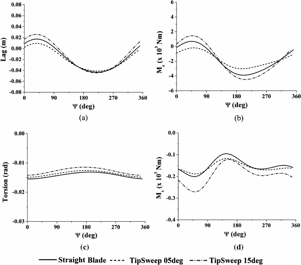
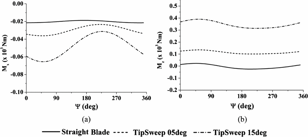
Figure 11 shows the effects of tip-sweep on blade response @ 0.7R and the root blade moments. The lag response and root lag moment show a slight reduction in peak-to-peak values for a small tip-sweep angle (5°); but at higher tip-sweep (15°), the peak-to-peak values show an increase. Flap response and root flap moment are hardly affected by tip-sweep and hence, have not been plotted. The torsion response is seen to decrease with increase in tip-sweep. This is due to the inertia of the tip portion providing a pitch-up moment to the blade. The root pitch-down moment is seen to increase in magnitude with increase in tip-sweep. Figure 12 shows the pitching and lag moments at the junction between the tip-sweep and straight portion of the blade. It is seen that tip-sweep increases these moments at the junction substantially.
Effect of tip-sweep on blade responses @ 0.7R and blade root moments with 2° lateral cyclic input and 5° collective. (a) Lag @0.7R (b) Root Lag Moment. (c) Torsion @0.7R (d) Root Pitching Moment.
Bending moments @0.9R for tip-sweep. (a) pitching moment (b) lag moment.
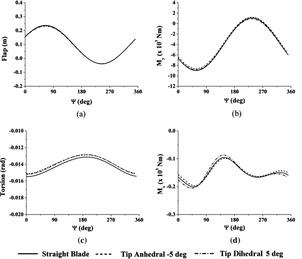
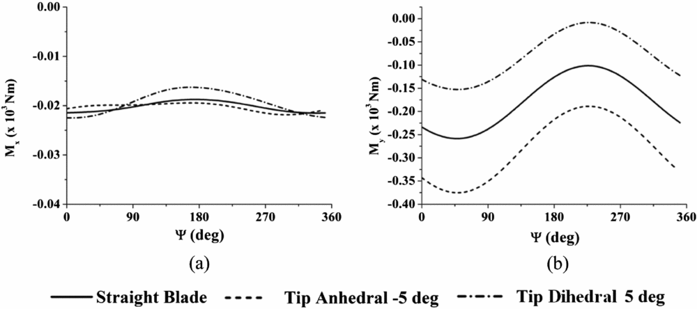
Figure 13 shows the effects of tip-anhedral on blade response @ 0.7R and the root blade moments. The lag response and root lag moment are hardly affected. The flap response and root flap moment also have negligible effects and hence, are not shown here. The most noticeable effect of tip-anhedral is the reduction in the torsion response. Figure 14 shows the pitching and flap moments at the junction between the tip-anhedral and straight portion of the blade. Just as in the case with only collective input, the flap moment is seen to be affected by tip-anhedral/dihedral. Tip-anhedral increased the negative flap moment while tip-dihedral has decreased it.
Effect of tip-anhedral on blade response @ 0.7R and on blade root moments with 5° collective and 2° lateral cyclic input. (a) Flap @0.7R (b) root flap moment. (c) Torsion @0.7R (d) root pitching moment.
Bending moments @0.9R for tip-anhedral. (a) pitching moment (b) flap moment.
6.0 CONCLUDING REMARKS
The influence of the blade geometric parameters on the structural dynamic characteristics, and response and loads of the rotor in a whirl tower simulation was studied. The key observations from this investigation are:
• The bending (lag and flap) frequencies can be tuned without affecting the torsion frequency by varying the hinge-offset.
• The torsion frequency can be tuned with least effect on the bending frequencies by varying tip-sweep and chord-wise placement of concentrated mass.
• As the span-wise location of a concentrated mass moves towards the blade tip, the first flap and lag frequencies are reduced.
• The second flap and lag frequencies initially increase and then decrease as a concentrated mass is moved towards the tip. The reason for this behaviour is a node observed near 0.75R in the mode shape. For a concentrated mass placed at a node, inertia effect is reduced but centrifugal effect is preserved.
In the whirl tower simulation, a cyclic pitch input was provided in addition to a collective pitch angle in order to generate oscillatory response and loads on the blade. From this study, it is observed that
• Tip-sweep increases the oscillatory lag moment at the blade root.
• Both tip-sweep and tip-anhedral decrease the elastic torsion deformation of the blade. However, the root pitching moment is significantly increased, especially, due to tip-sweep.
• Tip-sweep and tip-anhedral are found to alter the bending moments at the junction between the straight portion of the blade and the tip element. In particular, tip-sweep increases the lag bending moment while tip-anhedral increases the flap bending moment at the junction, substantially.
ACKNOWLEDGEMENTS
The authors thank Hindustan Aeronautics Limited, Bangalore, India for providing the financial support for this research work.
APPENDIX
The non-zero elements of the local-to-global transformation matrix, [Λ], for a tip element with tip-sweep and tip-anhedral are given here (Section 2.3):
Λ [1, 1] = cosΛs
Λ [1, 3] = sinΛs sinΛa
Λ [1, 6] = sinΛs cosΛa
Λ [2, 2] = cosΛa
Λ [2, 5] = −sinΛa
Λ [3, 3] = cosΛa
Λ [3, 6] = −sinΛa
Λ [4, 2] = sinΛs sinΛa
Λ [4, 4] = cosΛs
Λ [4, 5] = sinΛs cosΛa
Λ [5, 2] = cosΛs sinΛa
Λ [5, 4] = −sinΛs
Λ [5, 5] = cosΛs cosΛa
Λ [6, 1] = −sinΛs
Λ [6, 3] = cosΛs sinΛa
Λ [6, 6] = cosΛs cosΛa
Λ [7, 2] = 1/2 cosΛs sinΛa
Λ [7, 4] = −1/2 sinΛs
Λ [7, 7] = cosΛs cosΛa
Λ [7, 10] = 1/2 cosΛs sinΛa
Λ [7, 12] = −1/2 sinΛs
Λ [8, 1] = −1/2 sinΛs
Λ [8, 3] = 1/2 cosΛs sinΛa
Λ [8, 8] = cosΛs cosΛa
Λ [8, 9] = −1/2 sinΛs
Λ [8, 11] = 1/2 cosΛs sinΛa
Λ [9, 9] = cosΛs
Λ [9, 11] = sinΛs sinΛa
Λ [9, 14] = sinΛs cosΛa
Λ [10, 10] = cosΛa
Λ [10, 13] = −sinΛa
Λ [11, 11] = cosΛa
Λ [11, 14] = −sinΛa
Λ [12, 10] = sinΛs sinΛa
Λ [12, 12] = cosΛs
Λ [12, 13] = sinΛs cosΛa
Λ [13, 10] = cosΛs sinΛa
Λ [13, 12] = −sinΛs
Λ [13, 13] = cosΛs cosΛa
Λ [14, 9] = −sinΛs
Λ [14, 11] = cosΛs sinΛa
Λ [14, 14] = cosΛs cosΛa