
I. INTRODUCTION
Carbon nanomaterials such as carbon nanotubes and graphene possess interesting and sometimes unique physicochemical properties Reference Gogotsi and Presser1 suitable for energy, Reference Dai, Chang, Baek and Lu2 electromagnetic, Reference Bonaccorso, Sun, Hasan and Ferrari3 and biomedical Reference Feng and Liu4 applications. Manufacturing large macroscopic two- and three-dimensional assemblies of these nanomaterials are required for many of these applications including sensor development, Reference Dong, Wang, Wang, Song, Zhang, Huang and Chen5,Reference Kang, Schulz, Kim, Shanov and Shi6 solar cells, Reference Wang, Zhi and Müllen7 electromagnetic shielding, Reference Xu, Hu, Anlage and Gruner8,Reference Cao, Wang, Cao and Yuan9 fuel cells, Reference Maiyalagan, Dong, Chen and Wang10 and scaffolding. Reference Li, Zhang, Gao, Song, Huang, Wang, Liu, Dai, Tang and Cheng11
Spray coating, chemical vapor deposition, and vacuum filtration have been explored as methods to deposit two- and three-dimensional assemblies of carbon nanomaterials. However, none of these current technologies have been demonstrated to facilitate layer-by-layer additive manufacturing of three dimensional all-carbon nanomaterial structures or parts. Reference Huang, Liu, Mokasdar and Hou12–Reference Small16
Among these methods, spray coating is one of the most inexpensive and flexible manufacturing methods for creating thick surface coatings of carbon nanomaterials. Unlike other coating modalities, spray coating does not require a flat substrate, impose specific substrate chemistries for chemical growth of the nanomaterial, or exert high pressures and temperatures on the substrates. Reference Wang, Zheng, Xu, Dubuisson, Bao, Lu and Loh17–Reference Wu, Chen, Du, Logan, Sippel, Nikolou, Kamaras, Reynolds, Tanner and Hebard19 The layer-by-layer approach of spray coating allows for fine control of coating thickness. Also, recent advances in spray coating have significantly improved surface homogeneity Reference Tenent, Barnes, Bergeson, Ferguson, To, Gedvilas, Heben and Blackburn20 and the mechanical properties of spray coated carbon nanomaterial coatings. Reference Tait, Worfolk, Maloney, Hauger, Elias, Buriak and Harris21
Spray coating has been previously used to fabricate large surface area graphene Reference Pham, Cuong, Hur, Shin, Kim, Chung and Kim22 and carbon nanotube Reference Tenent, Barnes, Bergeson, Ferguson, To, Gedvilas, Heben and Blackburn20,Reference Ramasamy, Lee, Lee and Song23 films. The two main methods of spray coating include airbrush spraying techniques and ultrasonic spray coating. Airbrush spray coating involves application of an aerosolized dispersion of particles using a pressurized gas carrier. Airbrush spray coatings has been used to fabricated carbon nanotube coatings as substrates for stem cell differentiation, Reference Nayak, Jian, Phua, Ho, Ren and Pastorin24 carbon nanotube solar cell counter electrodes, Reference Ramasamy, Lee, Lee and Song23 and graphene based semiconductors. Reference Alver, Zhou, Belay, Krueger, Davis and Hickman25
Ultrasonic spray coating is a newer method which utilizes a high frequency actuated nozzle creating more homogenous droplets than airbrushing, with individual droplet volumes as low as picoliters in volume. Reference Steirer, Reese, Rupert, Kopidakis, Olson, Collins and Ginley26 In contrast to airbrush methods, ultrasonic spray nozzles also disperse the nanomaterials as the ultrasonic vibrations can disrupt particle aggregates and self-cleans at the nozzle to prevent nanomaterial accumulation at the spray head. Ultrasonic spray coating of carbon nanomaterials has been investigated for assembly of graphene-carbon nanotube composite electrochemical cells Reference Kim, Jeong, Higgins, Yu and Wallace27 and carbon nanotube photovoltaics. Reference Tenent, Barnes, Bergeson, Ferguson, To, Gedvilas, Heben and Blackburn20
While ultrasonic spray coating of carbon nanomaterials has worked well at laboratory scales a significant barrier that needs to be overcome to employ this method (or other deposition methods listed above) toward large-scale 2D and 3D printing of all carbon nanomaterials for many practical applications is the lack of strong chemical (covalent) bonding between the particles. For example, graphene and carbon nanotube coatings show prospect for orthopedic devices. However, these coatings lack structural robustness due to lack of chemical bonds between individual particles which can lead to loose nanoparticle related toxicity. Reference Tutak, Park, Vasilov, Starovoytov, Fanchini, Cai, Partridge, Sesti and Chhowalla28 Also, for some photovoltaic applications, such as solar panels, components fabricated using carbon nanomaterials which are 2D or 3D structures need to be durable and able to withstand various mechanical stressors. Thus, chemically association between individual nanomaterials that improve the structural stability of the components could be beneficial. Reference King, Quintana, Kratochvil, Ellibee and Hansen29
Recently, we reported a method to fabricate 3D, robust, free-standing multiwalled carbon nanotubes (MWCNT) porous scaffolds using a simple free-radical initiated crosslinking protocol. Reference Lalwani, Kwaczala, Kanakia, Patel, Judex and Sitharaman30 Using the same chemical crosslinking principle, Reference Sivertz, Andrews, Elsdon and Graham31 we also reported a method to fabricate in situ chemically-crosslinked coatings using MWCNTs via an airbrush spraying technique. Reference Patel, Lalwani, Grover, Qin and Sitharaman32 However, with airbrushing we noted some severe limitations. First, the pressure required to carry the solvent and create droplets reached over 20 psi, which can disrupt the coating, causing inhomogeneity on the surface and a high-surface roughness. Second, the droplets created by airbrushing are more inhomogeneous in size and volume compared to ultrasonic spray coating. Reference Wang, Purwanto, Lenggoro, Okuyama, Chang and Jang33
Herein we have combined our in situ carbon nanomaterial crosslinking method with ultrasonic spray coating to create smoother and more uniform chemically-crosslinked carbon nanomaterial coatings by a layer-by-layer ultrasonic spray coating approach. We also explore and compare the physiochemical properties coatings made with different types of carbon nanotubes and graphene nanoparticles. The in situ chemical crosslinking protocol allows excellent control over coating thickness and allows for fabrication of thick macroscopic coatings. Lastly, as a proof of concept, we present the potential of this technique to build layer-by-layer assembled, free-standing, three dimensional crosslinked carbon nanotube structures as a first step toward additive manufacturing of all carbon assemblies.
II. MATERIALS AND METHODS
A. Materials
Multi-walled carbon nanotubes of high diameter (MWCNT-H) and multi-walled carbon nanotubes of low diameter (MWCNT-L) were purchased from Sigma Aldrich (St. Louis, MO, USA). The free radical initiator, benzoyl peroxide (BP) and anhydrous ethyl acetate was also purchased from Sigma Aldrich (St. Louis, MO, USA). Single-walled carbon nanotubes (SWCNT) and research-grade graphene oxide nanoplatelets (GONP) were purchased from CheapTubes (Cambridgeport, VT, USA). Graphene oxide nanoribbons (GONR) were provided by AZ Electronic Materials (Branchburg, NJ, USA), available from Sigma Aldrich (St. Louis, MO, USA).
B. Film fabrication
For each carbon nanomaterial geometry, 0.4–1.0 mg/mL dispersions were made in anhydrous ethyl acetate and subsequently treated by bath sonication for 1 h to disperse aggregated particles. To initiate in situ crosslinking of nanomaterials, BP was added to each solution at a 1:4 mass ratio of nanomaterial to BP shortly before spraying. Spray coating was conducted in a rastering pattern utilizing an automated XYZ gantry with an ultrasonic spray nozzle (Sonaer Ultrasonics, Farmingdale, NY, USA). The nanomaterial and BP were fed to the nozzle by a syringe pump with flow rates varying according to the speed of the x–y motion and nanoparticle concentration. The suspensions were coated onto 12 mm diameter commercially pure (Grade 2) titanium circles fabricated by Wyoming Machine (Stacy, MN, USA). A total of 30 spray coated passes were made on each titanium circle during the spray coating process. Additionally, inert nitrogen gas was fed into the spray nozzle to shape the spray into a conical shape as it exits the spray head. While spray coating, the titanium circles were affixed to a custom fabricated aluminum vacuum chuck. The vacuum chuck was placed directly onto an aluminum hotplate with a set point temperature of 135 °C. The temperature at the surface of the titanium was found to be around 90 °C as measured by a laser guided heat gun (Fluke, Everett, WA, USA).
C. Layer-by-layer fabrication of 3D structures
Three dimensional structures were fabricated using a dispersion of 1.0 mg/mL SWCNT in chloroform which were dispersed via bath sonication for 1 hour prior to spraying. Similar to the 2D coatings, BP was added to the solution at a 1:4 mass ratio of SWCNT to BP shortly before spraying. The solution was sprayed into a cylindrical well made by drilling a 3/16″ diameter hole in an aluminum block. The ultrasonic spray nozzle rasterized between three wells above the mold. While spraying the mold was placed on an aluminum hotplate with a set point temperature of 105 °C. The resultant 3D carbon nanotube architecture was removed from the well by gently dislodging it using a sharp 27 gauge needle and sharp tweezers.
D. Electron microscopy
Scanning electron microscopy (SEM) analysis was performed at Brookhaven National Lab on a JEOL 7600 analytical high-resolution SEM. Carbon nanomaterial films on titanium discs were sputter coated with 3 nm of silver to prevent surface charge accumulation and provide higher resolution imaging.
Transmission electron microscopy (TEM) of crosslinked thin films were performed on lacey carbon TEM grids (Ted Pella, Redding, CA, USA). Each coating surface was scratched with sharp tweezers and the fragmented coating was placed over the lacey carbon grid. TEM was performed at Brookhaven National Lab on a JOEL 1400F analytical TEM at 80 kV accelerating voltage.
E. Atomic force microscopy
For atomic force microscopy (AFM), the crosslinked films on titanium substrates were probed with a NanoSurf EasyScan 2 Flex AFM (NanoScience Instruments Inc., Phoenix, AZ). AFM was performed in tapping-mode by a V-shaped cantilever (APP Nano ACL−10, frequency fc = 145–230 kHz, L = 225 μm, W = 40 μm, tip radius <10 nm, spring constant k = 20–95 N/m) mounted on a 10 × 10 μm scan head. NanoSurf Easy Scan 2 software was utilized to calculate the root mean square (r.m.s.) area surface roughness of the coatings.
F. Raman spectroscopy
Raman spectroscopy (Enwave Optronics, Irvine, CA) was performed in five regions of each sample under a 40× objective using a 532 nm laser source. Point spectra scanning from 100 to 3100 cm−1, at room temperature, were acquired for analysis.
G. Mechanical testing-nanoindentation
Quasi-static nanoindentaiton was used to find the elastic modulus and hardness of the various carbon nanoparticle coatings. The coated titanium disks were subsequently attached to AFM specimen disks (Ted Pella, of 15 mm diameter), which were finally mounted on the magnetic base of the nanoindenter (Hysitron, Minneapolis, MN, USA). Points of indentation were chosen using the imaging system of the triboindenter (with an objective of 10× magnification and eyepiece of 2× magnification), after careful analysis. The selection of the indentation took account of the porous structure of the samples. Each point was selected at a distance no less than 100 μm away from the others. Each indentation further comprised of 9 sub-indents in a 3 × 3 pattern. The tip area function was calibrated from indentation analysis on fused quartz, and drift rates in the system were measured prior to each indentation. For each indentation, first, a preload of 3 μN was applied to the system followed by a constant loading rate (10 μN/s). Next, a hold segment at a fixed system load was applied, followed by a constant unloading rate to retract the tip (−10 μN/s), and finally another hold segment was applied (3 μN). Each sample was indented with a peak load of 50 μN. The elastic response was calculated from the 20–90% portion of the unloading curve using methods previously described. Reference Ozcivici, Ferreri, Qin and Judex34 Indentation depth of less than 500 nm were rejected as an exclusion criteria, due to the possibility of probing the titanium substrate. Statistical analysis was performed using GraphPad Prism 4 using a nonparametric analysis of variance (Kruskal–Wallis test) with multiple comparisons post hoc test (Dunn’s multiple comparison test).
To determine the nanoscale viscoelastic properties of crosslinked carbon nanomaterial coatings, nanoscale dynamic mechanical analysis (nanoDMA) was carried out by using a nanoindenter (Hysitron, Minneapolis, MN, USA) with a Berkovich indenter tip. Reference Li and Bhushan35 The specimens were fixed on AFM specimen discs (Ted Pella) and firmly mounted onto the magnetized base of the nanoindenter. Samples were indented 10 single indents each time to determine the average loss modulus, storage modulus and subsequently the respective phase angle (δ). The indentations were performed at room temperature. After calibration, frequency mode were used for the nanoDMA testing. A quasistatic load of 1 µN at a loading rate of 10 µN/s was applied to the sample. Superposed on the load was a 0.1 µN dynamic load with a frequency range of 10–250 Hz. The quasistatic load was determined to limit the depth of the indentation to be within 1000 nm so that the tip of the indenter did not puncture the carbon film and engage with the titanium substrate. The storage and loss modulus were determined by Reference Xiaodong, Hongsheng, Wally, Dongling, Xiaoyou, Michael, Anthony and Michael36 :
 $$E' = {{{K_{\rm{s}}}\sqrt \pi } \over {2\sqrt A }}\quad .$$
 $$E'' = {{\omega \cdot {C_{\rm{s}}}\sqrt \pi } \over {2\sqrt A }}\quad .$$
Where K s is the dynamic stiffness and C s is the dynamic damping coefficient, A is the projected contact area of the Berkovich tip used in this study and ω is the frequency in radians per second. Tan (δ), or the damping from the material, was determined by E″/E′.
H. Micro-computed tomography
A high-resolution micro computed tomography (μCT) scanner (μCT-40, SCANCO Medical AG, Bassersdorf, Switzerland) was used for scanning of the macroscopic 3D SWCNT structures to characterize the porosity and 3-D structure of the material. The samples were placed in a cylinder with rigid foam supports in the sample holder, and scanned with a spatial resolution of 6 μm. Specific Gaussian sigma, support, lower threshold and upper threshold were set to be 0.3, 1, 28, and 60, respectively, for image smoothing purposes.
I. Thermogravimetric analysis
Thermogravimetric analysis (TGA) was performed on three-dimensional structures made by chemically crosslinking SWCNT in a layer-by-layer approach. The porous three dimensional structure was placed in an aluminum pan and the mass was recorded using a Perkin Elmer TGA (Waltham, MA, USA) while heating the sample from 100 to 550 °C at a rate of 5 °C/min with oxygen purging.
III. RESULTS AND DISCUSSIONS
A. Two-dimensional coatings
Carbon nanomaterials, of various sizes and architectures, were coated onto heated titanium substrates to trigger in situ crosslink formation. We utilized carbon nanotubes of varying diameters, as specified by the producer, including SWCNT (1–4 nm diameter), MWCNT-L (40–70 nm diameter), and MWCNT-H (110–170 nm diameter). For graphene coatings, two allotropes of graphene were used: GONP (few layer, 1–2 μm grain size) and GONR (∼400–700 nm in width as measured by TEM). As previously reported, BP was used as a free radical initiator to create crosslinks between the nanoparticles Reference Patel, Lalwani, Grover, Qin and Sitharaman32 as the ethyl acetate droplets evaporated at the heated titanium surface.
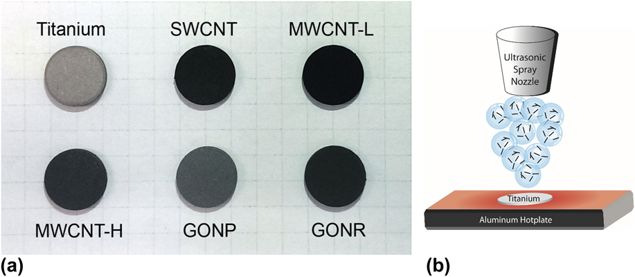
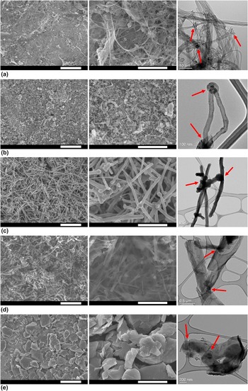
Photographs of the titanium substrates and the coatings for each type of nanomaterial are shown in Fig. 1(a). An illustrated schematic of the ultrasonic spray coating process is shown in Fig. 1(b). GONP coated as a dark gray color while the remainder of the materials coated to form a dark black coating. Each coating was characterized using scanning electron microscopy (SEM) and transmission electron microscopy (TEM) and is shown in Fig. 2. Low magnification (Fig. 2, left panel) SEM images show the continuity of the coatings. High magnification (Fig. 2, middle panel) SEM images show the relative size scales of the particles. In Fig. 2(c) (middle panel), the crosslink junctions between MWCNT-H can be observed. The crosslinks for the other materials are better visualized by TEM as shown by the red arrows in the right-most panel of Fig. 3. By TEM, dense rope structures of SWCNT are seen, characteristic of SWCNT which are not treated to harsh, oxidizing acidic solutions to separate the bundles. Reference Xie, Gao, Patel, Booske, Hagness and Sitharaman37 As the diameter of the nanotubes increases (from SWCNT to MWCNT-H), the structures are also visibly more rigid and linear where SWCNT exist as entangling ropes while MWCNT-H are more like rigid rods. Carbon nanotube coatings formed a mesh-like network, while the graphene allotropes were stacked on their planar surfaces as they were sprayed onto the titanium [Figs. 2(d) and 2(e), left column]. TEM analysis of the fragmented coatings (Fig. 2, right column) was performed to observe the crosslinks between the nanoparticles. SWCNTs existed in ropes but still had a few noticeable junctions which suggest crosslinking, while MWCNT-L, MWCNT-H, and GONR had more obvious junctions between the individual particles as indicated by the red arrows. Corroborating with SEM images, TEM observation of GONP indicates planar stacking and suggests crosslinking of the graphene sheets to create larger sized graphitic fragments with crosslinks forming between one or more sheets as indicated by the red arrows. While TEM results suggest crosslinking, evidence of crosslinking is based on all the other characterization results taken together.
(a) Photographs of titanium substrates coated with in situ chemically crosslinked SWCNT, MWCNT-L, MWCNT-H, GONP, and GONR. (b) An illustrated schematic of ultrasonic spray coating process.

Electron microscopy of chemically crosslinked carbon nanomaterial films. The left column shows low magnification SEM images (scale bars: 5 μm) and the middle column shows higher magnification SEM images (scale bars 2 μm). The right column shows TEM images of fragmented carbon nanomaterial films and junctions (red arrows) between nanoparticles. Each carbon nanomaterial is shown in the following corresponding rows: (a) SWCNT, (b) MWCNT-L, (c) MWCNT-H, (d) GONR, and (e) GONP.

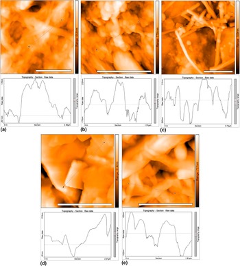
Representative AFM images and line graphs showing regions of interest of ultrasonic spray coated, chemically crosslinked (a) SWCNT, (b) MWCNT-L, (c) MWCNT-H, (d) GONR, and (e) GONP coatings on titanium substrates. Each scale bar is 2 μm in width.

Surface roughness and topography were studied using AFM. Representative AFM images of each crosslinked carbon nanomaterial coating is presented in Fig. 3. Samples were probed in AFM tapping mode in multiple regions of multiple coatings (n = 10). Surface roughness measurements were determined from a total of 10 regions for each group. Each of the nanomaterials showed regions of dense packing as shown in Fig. 3. Line plots of SWCNT [Fig. 3(a)] show small peaks nested inside larger topographical features while fewer nested peaks are observed in the MWCNT-L [Fig. 3(b)], and even fewer in MWCNT-H [Fig. 3(c)]. GONP had large planar sheet-like structures which had high intrinsic topography shown in the line plot of Fig. 3(d). GONR were visibly planar with long [Fig. 3(e)], flat structures randomly oriented in the x–y direction. Surface roughness (r.m.s) measurements were performed on the titanium substrates and the crosslinked carbon nanomaterial coatings (Table I). The titanium substrates had surface roughness of 110.79 nm. The additional coating of the crosslinked carbon nanomaterials increased the overall surface roughness to 125.56–225.45 nm. Increasing the diameter of the carbon nanotubes from SWCNT to MWCNT-H resulted in an increase in surface roughness due to the diameter of the tubes. However MWCNT-L (125.56 nm) had a lower surface roughness than SWCNT (179.65 nm). The increased surface roughness in SWCNT coatings compared to MWCNT-L coatings, may be due to the SWCNT existing in large rope-like bundles unless pre-treated with acidic solutions. Reference Xie, Gao, Patel, Booske, Hagness and Sitharaman37 Both graphene structures, GONP and GONR, showed comparable surface roughness, between 162.63 nm and 172.81 nm.
Surface roughness (r.m.s) of titanium substrates and crosslinked carbon nanomaterial coatings as measured by AFM (n = 10 for each group).

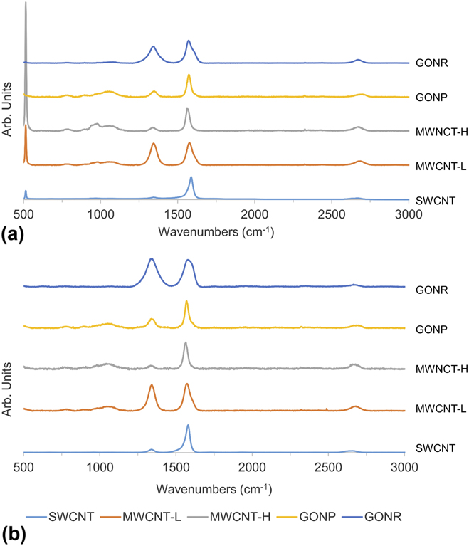
Raman spectroscopy was utilized to characterize the chemical properties of the carbon nanomaterial crosslinked coatings. Raman spectra of each pristine nanomaterial (nanomaterial drop casted onto a silicon wafer without any treatments) and chemically crosslinked coatings (on titanium discs) are presented in Fig. 4(a) and Fig. 4(b), respectively. Characteristic Raman peaks of carbon nanomaterials include three prominent peaks at ∼1345 cm−1, 1560 cm−1, and 2670 cm−1, identified as the D, G, and G′ bands respectively. Reference Dresselhaus, Dresselhaus, Saito and Jorio38 Pristine sp 2 hybridized carbon nanomaterials share a characteristic G band (intensity of which is I G) generated by in-plane vibrations of double bonded carbon atoms. Reference Ferrari39 Defect structures, identified by the D band (intensity of which is I D), are caused by structural defects or sp 3 bonds in the graphitic network. Reference Dresselhaus, Dresselhaus, Saito and Jorio38 The relative amounts of defect structures between groups can be identified by the I D/I G ratio. We found an increase in the I D/I G ratio for each group (n = 3) of chemically crosslinked carbon nanoparticle when compared to its pristine counterpart (Table II). The increase in I D/I G ratio for crosslinked coatings may be attributed to radical initiated crosslinking forming junctions on the surface of adjoining nanoparticles. Notably, the I D/I G ratio of the crosslinked SWCNT and GONP groups nearly doubled as compared to their pristine counterparts. While the I D/I G ratio in the crosslinked SWNCT and GONP groups increased, the defect concentration in the crosslinked SWCNT group is still less than the pristine MWCNT-L and MWCNT-H materials, while the defect concentration in the crosslinked GONP group is lower than in the pristine GONR material. Along with the chemical crosslinking, the increase in I D/I G ratio may be attributed to the sonicating of the nanoparticles for an extended duration of time to debundle the aggregated SWCNT and exfoliate larger GONP to fewer layer particles as sonication has shown the ability to damage sp 2 hybridized carbon nanoparticles. Reference Gojny, Wichmann, Fiedler and Schulte40 Another reason for the disparity in Raman spectra for SWCNT films compared to the other nanotube groups is the surface area available for crosslinking. In case of SWCNTs, each nanotube is prone to effects from the benzoyl peroxide. For MWCNT, this may not be case; their concentric tubular structures most likely protects the inner nanotube layers from the benzoyl peroxide reaction.
Representative Raman spectrographs of (a) pristine carbon nanomaterials drop casted on silicon substrates and (b) chemically crosslinked carbon nanomaterial coatings on titanium substrates.

Normalized Raman I D/I G ratios for pristine carbon nanoparticles on silicon substrates and chemically crosslinked carbon nanoparticles on titanium substrates (n = 3 for each group).

For many applications of carbon nanomaterials, including solar cells, personal devices, medical devices and implants, etc., mechanical analysis of the carbon nanomaterial assembly is required. Nanoindentation was performed on the crosslinked carbon nanomaterial coatings to characterize the mechanical properties of the coatings. Quasistatic indentation was performed to measure the elastic modulus (Table III) and hardness (Table IV) from the unloading curve of the indentation. Quasistatic indentation revealed SWCNT groups to have the lowest elastic modulus (79 MPa), two orders of magnitude less than all other experimental groups, and significantly less than MWCNT-L, GONP, and GONR groups. MWCNT-H also had a significantly lower elastic modulus (1.18 GPa) compared to MWCNT-L and GONR. The nanoindentation also measured hardness revealing similar results. Measured hardness of SWCNT (1.843 MPa) was significantly less than all other experimental groups. Here, however, there was only one order of magnitude difference between SWCNT and other experimental groups. GONR showed the greatest hardness (97.52 MPa), significantly greater than both MWCNT-H and GONP groups. An exclusion criteria of contact depth was imposed on the quasistatic indentation. We wanted to measure the mechanical properties of the crosslinked coating, rather than effects due to the substrate. Shallow indentation depths were found to have mechanical properties resembling that of the titanium substrate (data not show). This is likely due to the sensitivity of the nanoindenter probe, recognizing the porous crosslinked nanomaterial structure after breaking through the top layers of the coating. To avoid confounding our results with substrate-related mechanical properties, where the indentation may start at a pore or a thin region of the film, we only collected data from points where contact depth was greater than 500 nm.
Elastic modulus determined by quasi-static nanoindentation of chemically crosslinked carbon nanomaterial coatings. All data is reported in median, interquartile range (I.Q.R), average, and standard deviation (significant differences are observed as follows: *P < 0.01, **P < 0.001).

Mechanical hardness determined by quasi-static nanoindentation of chemically crosslinked carbon nanomaterial coatings. All data is reported in median, interquartile range (I.Q.R), average, and standard deviation (significant differences are observed as follows: *P < 0.05, **P < 0.01, ***P < 0.001).

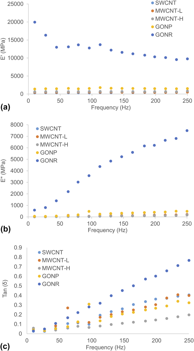
Nanoscale dynamic mechanical analysis (nanoDMA) was utilized to understand the viscoelastic properties of the coatings. For SWCNT and MWCNT-H, the storage modulus (G′) increased 44 and 22%, respectively when scanning from 10 to 250 Hz [Fig. 5(a)]. MWCNT-L and GONP, only observed marginal increases in G′ (14 and 7.8% respectively) from 10 to 250 Hz. Interestingly for GONR, the G′ decreased 104% in the same frequency sweep [Fig. 5(a)]. The loss modulus of each increased by 77–96% for any group [Fig. 5(b)]. Tan (δ), a measure of energy dissipation as a function of G″/G′, increased for each group from 10 to 250 Hz, with GONR having the greatest rate of increase from all of the groups and MWCNT-H having the lowest rate of increase [Fig. 5(c)]. Therefore, carbon nanotube based damping observed through nanoDMA suggests higher viscoelastic response in SWCNT and MWCNT-L coatings compared to MWCNT-H [Fig. 5(c)].
Nanoscale dynamic mechanical analysis of crosslinked carbon nanoparticles coatings. Frequency sweep measurements of (a) storage modulus, (b) loss modulus, and (c) tan (δ) are presented for each group.

Spray coating of carbon nanomaterial dispersions provides a lot of heterogeneity in the film surface roughness. While airbrushing techniques can make carbon nanomaterial films, it requires the nanomaterials to be dispersed with a surfactant like carboxymethyl cellulose or sodium dodecyl sulfate. Reference Tenent, Barnes, Bergeson, Ferguson, To, Gedvilas, Heben and Blackburn20 While the smoothest carbon nanotube films (∼3 nm r.m.s. surface roughness) Reference Tenent, Barnes, Bergeson, Ferguson, To, Gedvilas, Heben and Blackburn20 were spray coated using ultrasonic spray coating, these required an amphiphilic surfactant to disperse the materials. In this technique, we refrained from using any such dispersants for two primary reasons: (i) we wanted to fabricate coatings of only carbon nanomaterials to better exploit their physicochemical properties and (ii) the usage of any surfactant could have resulted in the radical initiator forming chemical functionalities on the nanomaterials and inert surfactants would compete with surface area available for radical sites to form on the carbon nanoparticles. We observed significantly smoother and more uniform coatings utilizing ultrasonic spray coating to fabricate crosslinked MWCNT-H coatings (225.45 nm) than our previous reports of fabricating such films using an airbrush technique (730 nm). Reference Patel, Lalwani, Grover, Qin and Sitharaman32 Also, although we cannot directly subtract a baseline surface roughness from the titanium substrate, some of the surface roughness of the crosslinked carbon nanomaterial coatings may also be attributed to the underlying titanium substrate.
Spray coating can be optimized by using highly sensitive and precise inlet flow and axial motion. A limitation to the technique is that the films created by spray coating are usually more inhomogeneous than both CVD and vacuum filtration techniques. In the case of CVD, the growth of the graphene or carbon nanotubes is well controlled and relatively homogenous on the surface of the catalyst material. Reference Suk, Kitt, Magnuson, Hao, Ahmed, An, Swan, Goldberg and Ruoff41 Vacuum filtration allows for homogenous film fabrication because the technique can auto-correct itself. The permeation of the solvent containing nanoparticles would be more hindered in regions where there is more accumulation, forcing the solvent to flow through less densely packed areas. Reference Wu, Chen, Du, Logan, Sippel, Nikolou, Kamaras, Reynolds, Tanner and Hebard19 However, these techniques have limited versatility. While CVD can produce highly homogenous coatings of carbon nanotubes or graphene, it requires the substrate to be heated to high temperatures and requires particular surface chemistries for growth to occur. Reference Mattia, Rossi, Kim, Korneva, Bau and Gogotsi42,Reference Franklin and Dai43 Spray coating only requires mild heating depending on the carrier solvent chosen. Vacuum filtration requires a flat porous membrane to fabricate films and can be made into a free standing film. Reference Wu, Chen, Du, Logan, Sippel, Nikolou, Kamaras, Reynolds, Tanner and Hebard19,Reference Eda, Fanchini and Chhowalla44,Reference Ci, Manikoth, Li, Vajtai and Ajayan45 However, the surface in which these films are to be transferred must also be flat to prevent wrinkling of the film. Spray coating allows for coating on many substrate geometries.
It is important to understand the mechanical properties of these coatings since different applications required distinct mechanical properties. For example, touchscreen coatings would require greater hardness or improved viscoelastic response for scratch- and fracture-resistance, Reference Jardret and Morel46 while bone implant coatings may require greater elastic modulus to prevent stress shielding. Reference Niinomi and Nakai47 Previous nanoDMA work with carbon nanotubes and boron nitride nanotubes suggests thicker diameter tubes are more constricted in their ability to slide in a network because of their intrinsic stiffness. Reference Agrawal, Nieto, Chen, Mora and Agarwal48 Constricted sliding in these networks of nanotubes can also be attributed to the chemical crosslinking at the surface of the nanotubes, which would be greater in MWCNT-H since theoretically, there would be more crosslinks per nanotube than in SWNCT or MWCNT-L. CVD grown graphene, transferred to a silicon substrate, with few layers (∼5 layers) and multi-layered (∼10 layers) graphene also indicated a dominant role in frequency dependent damping behavior due to ripple formation and propagation in the graphene layers and energy adsorption by the stacking of layers (by van der Waals forces). Reference Lahiri, Das, Choi and Agarwal49 Thicker (10 layer) graphene had a more pronounced increase in tan (δ) after 150 Hz, with the increased damping due to the increased accommodation of ripple propagation in the z-direction. Reference Lahiri, Das, Choi and Agarwal49 Still, this explanation does not explain why tan (δ) increased faster in GONR than GONP in our studies. Perhaps this faster increase is because of the intrinsic folding of the GONR during synthesis; Reference Kosynkin, Higginbotham, Sinitskii, Lomeda, Dimiev, Price and Tour50 theoretically increasing the space for z-axis ripple propagation, and further increasing the spring like behavior of the GONR matrix. An interesting comparison would have been with coatings of pristine carbon nanomaterial coatings to assess whether the chemical crosslinking was facilitating more robust coatings. However, we were not able to fabricate coatings of appreciable thicknesses without the crosslinking method. Thinner coatings (<1 μm) would not be acceptable for mechanical analysis since the probing method may also include the mechanical properties of the underlying titanium substrate.
B. Three dimensional assemblies
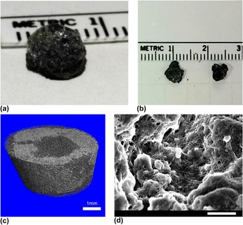
Since the ultrasonic spray coating, layer-by-layer in situ crosslinking of the carbon nanoparticles lead to macroscopic coatings, we also wanted to examine if this technique could be utilized for creating free standing macroscopic 3D architectures. As a proof of concept, we used SWCNT to fabricate the 3D structures. Using the same SWCNT:BP ratio (1:4), we spray coated the dispersion in three aluminum wells fabricated in an aluminum block. Aluminum was chosen because it is inert to the reagents utilized, while it provides good heat conduction to the structures as they are built up three-dimensionally. The three dimensional structures were removed from the wells after being heat treated in an oven at 150 °C for about one hour to remove excess benzoyl peroxide, as suggested in previous reports. Reference Lalwani, Kwaczala, Kanakia, Patel, Judex and Sitharaman30 Photographs of the 3D structures are shown in Fig. 6(a). The structures maintained the conical shape of their wells and even structures which break apart maintained macroscopic 3D structures [Fig. 6(b)]. The 3D all-carbon structures were visibly porous and the porosity/microstructure was further investigated by μCT analysis. 3D reconstructions of the μCT slices were rendered to visualize the porosity of the assemblies [Fig. 6(c)]. A rectangular prism section from inside the scaffold structure was chosen to evaluate for porosity measurements to prevent subjective contouring on the irregular edges of the porous structure. The mean porosity of the 3D SWCNT assemblies was approximately 68% (SD = 9.3%) as measured by μCT. SEM analysis of the 3D SWCNT assembly [Fig. 6(d)] was performed, revealing a network of crosslinked, interconnected bundles of SWCNT.
(a) Photographs of a free standing, three-dimensional, chemically crosslinked, layer-by-layer assembled SWCNT structure and (b) fragmented macroscopic pieces of the crosslinked SWCNT structure. (c) 3D image reconstructions from μCT analysis of three dimensional SWCNT structures. Each slice of the reconstruction is approximately 6 μm in thickness (scale bar: 1 mm). (d) SEM image from inside a pore of a 3D chemically crosslinked SWCNT structures (scale bar: 2 μm).

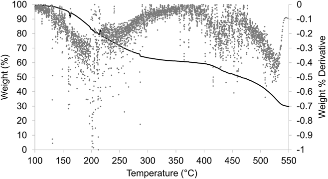
To analyze overall functionalization and the chemistry of the 3D SWCNT assemblies, we performed TGA on the SWCNT architectures (Fig. 7). Three major weight loss peaks were observed, when plotting the second derivative of the TGA plot, at ∼210, 425, and 530 °C. At 210 °C, a total of 19.31% weight loss was observed. At 425 °C and 530 °C, a total of 24.56% and 22.41% weight loss was observed, respectively. By 550 °C only 29.65% of the total weight remained in the aluminum crucible. The thermal stability of SWCNTs has been previously reported to have weight loss deflections between 350–425 Reference Hu, Zhao, Itkis and Haddon51,Reference Shi, Lian, Liao, Zhou, Gu, Zhang and Iijima52 and ∼570 °C. Reference Xie, Gao, Patel, Booske, Hagness and Sitharaman37 Therefore we believe that the weight loss deflection at ∼210 °C of approximately 19.31% is attributed to defect sites on the carbon nanotubes formed during crosslinking and radical reactions from the BP as well as any amorphous, degraded carbon in the sample. Therefore, we estimate that more than 80% of the carbon nanotube material of the 3D carbon nanotube structures is intact SWCNT and any trace metal catalyst from the nanotube growth process. Reference Xie, Gao, Patel, Booske, Hagness and Sitharaman37
TGA plot of layer-by-layer assembled 3D crosslinked SWCNT architectures. Percentage of total weight (solid curve) and the first derivative plot (dotted curve) are shown.

Previously, we have shown the ability to fabricate 3D, chemically crosslinked, all carbon scaffolds from graphene and carbon nanotubes. Reference Lalwani, Kwaczala, Kanakia, Patel, Judex and Sitharaman30 In that work, we have fabricated scaffolds in a cylindrical mold by pouring a slurry the carbon nanoparticles mixed with free radical initiator. The porosity of the carbon nanotube scaffolds were tunable from ∼20 to 85% depending on the ratio of weights of nanomaterial: radical initiator. Reference Lalwani, Kwaczala, Kanakia, Patel, Judex and Sitharaman30 As an alternate strategy the layer-by-layer ultrasonic spray deposition could allow tuning porosity by decreasing the concentration of the nanoparticle dispersion to deposit thinner layers due to the fewer amount of nanoparticles per spray coating pass.
Another method to create highly porous graphene or carbon nanotube assemblies (porosity of over 99%) is via aerogel formation. Reference Hu, Zhao, Wan, Gogotsi and Qiu53–Reference Bryning, Milkie, Islam, Hough, Kikkawa and Yodh55 Typically these materials have small pores, from nanometer to a few micrometer size range Reference Bryning, Milkie, Islam, Hough, Kikkawa and Yodh55 which can be advantageous for applications in gas storage Reference Worsley, Pauzauskie, Olson, Biener, Satcher and Baumann54 or electrochemical cells. Reference Bordjiba, Mohamedi and Dao56 However, these assemblies have not been reported to exhibit macropores which are required for potential applications of carbon nanomaterials assemblies such as porous membranes, Reference Park and Xia57,Reference Park, Kim, Yoon, Lee, Ahn, Lee, Roh and Kim58 bioreactors, Reference Wang and Caruso59,Reference Xie, Hu, Pasta, Wells, Kong, Criddle and Cui60 or scaffolding in tissue repair. Reference Murphy, Dennis, Kileny and Mooney61,Reference Goenka, Sant and Sant62
The above demonstration of layer-by-layer ultrasonic spray coating and in situ crosslinked 3D all carbon assemblies suggests that this method could be adapted to enable additive manufacturing using carbon nanomaterials. While this method facilitates layer-by-layer assembly of carbon nanotubes, it requires further refinement to control x–y resolution and layer thickness. To the best of our knowledge, currently, the only commercially available carbon nanomaterial/polymer filament have been demonstrated to facilitate 3D printing. 63 Our method could uniquely facilitate additive manufacturing of all-carbon assemblies without the use of a polymeric phase, surfactants, or other binders.
IV. CONCLUSIONS
Layer-by-layer assembly of chemically crosslinked carbon nanoparticles (SWCNT, MWCNT, GONP, and GONR) by ultrasonic spray coating allows for fabrication of thick carbon nanomaterial coatings with more surface uniformity than a previously reported airbrush method. The crosslinking method keeps the carbon nanomaterial sp 2 hybridized backbone largely intact. Static and dynamic mechanical characterization indicate that the coatings are structurally robust and exhibit some viscoelastic behavior. The method also allows fabrication of chemically-crosslinked, free standing, macroscopic, three dimensional all-SWCNT structures and could be easily be adapted for 3D printing of all-carbon macroscopic assemblies with other carbon nanomaterials. The results taken together opens avenues for additive manufacturing scalable fabrication of robust 2D and 3D carbon nanomaterial assemblies with excellent control on coating thickness, and surface roughness.
COMPLIANCE WITH ETHICAL STANDARDS
Funding: This work was sponsored by National Institutes of Health grants (1DP2OD007394 and AR61821).
Conflict of Interest: Stony Brook University, Dr. Balaji Sitharaman, and Dr. Sunny Patel have filed patents related to the technology reported in this article. If licensing or commercialization occurs, the researchers are entitled to standard royalties.
ACKNOWLEDGMENTS
SEM, TEM, and TGA were conducted at Center for Functional Nanomaterials at BNL, supported by the U.S. Department of Energy, Office of Basic Energy Sciences, under Contract No. DE-AC02-98CH10886. We would also like to acknowledge Kamal James for helping in collecting Raman spectroscopy data.