1. INTRODUCTION
Vector global navigation satellite systems (GNSS) tracking and deep inertial navigation system (INS)/GNSS integration improve robustness and accuracy in poor GNSS signal-to-noise environments. Both require a dedicated interface between the GNSS receiver and the navigation processor to enable the GNSS receiver to output the accumulated correlator measurements, known as Is & Qs, and input numerically-controlled oscillator (NCO) commands. Standard GNSS interface protocols do not support this. For stand-alone GNSS vector tracking, the GNSS receiver and navigation processor will usually be produced by the same manufacturer, enabling use of a proprietary interface. However, deep INS/GNSS integration requires interoperability of inertial measurement units (IMU) and GNSS receivers produced by different manufacturers. Consequently, a standard interface between GNSS receiver and navigation processor is highly desirable.
The paper begins with an introduction to vector tracking and deep INS/GNSS integration. Section 2 then discusses data latency across the interface and within the GNSS receiver and navigation processor, its effects on signal tracking and compensation techniques. Section 3 analyses the maximum accelerations and jerks that may be tolerated for different interface rates and latency compensation schemes. Finally, Section 4 proposes an approach to interface standardisation which can handle a wide range of different GNSS signals and receiver designs.
Note that only GNSS receivers performing hardware signal correlation fall within the scope of this paper. In a ‘software receiver’, the signal correlation, tracking and navigation will share a processor, thus no external interface is required. Many of the data latency issues are also eliminated. However, the processor load is much higher.
1.1. Vector GNSS tracking
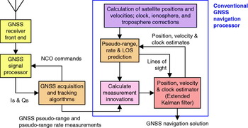
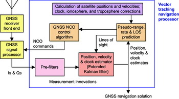
Figures 1 and 2 show, respectively, a conventional and a vector-tracking GNSS user equipment architecture [Reference Misra and Enge1–Reference Groves3]. In both cases, the front end amplifies, filters, down-converts and samples the GNSS signals. Then, in the baseband signal processor, the signals are correlated with internally-generated replicas of the GNSS signal code and carrier, sometimes known as references. Separate correlation channels are implemented for each signal tracked. The in-phase and quadrature accumulated correlator outputs, known as Is and Qs, are then output to the acquisition and tracking algorithms at intervals varying between 1 and 20 ms according to receiver design.
Conventional GNSS user equipment architecture.

Vector-tracking GNSS user equipment architecture.

Numerically-controlled oscillators determine the phase of the internally-generated code and carrier. For each signal tracked, there are two NCOs, one for code and one for carrier. NCOs are essentially digital integrators. Each time a pulse is received from the GNSS receiver's clock, the NCOs cause the internally-generated code and carrier to be advanced by an amount determined by the NCO command. Thus the NCO commands are proportional to the frequencies of the internally-generated code and carrier.
To use a GNSS signal for ranging, it is necessary to align the internally-generated spreading code with that of the incoming signal in order to recover the carrier and navigation data message. The internally generated carrier frequency must also be aligned with that of the incoming signal to prevent destructive interference due to phase rotation over the coherent accumulation time.
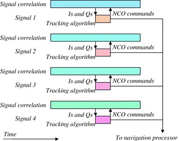
In the conventional GNSS architecture (Figure 1), NCO commands are generated by the user equipment's acquisition and tracking algorithms, inputting the Is and Qs [Reference Misra and Enge1–Reference Groves3]. These are implemented independently for each signal tracked as shown in Figure 3. In tracking mode, a delay lock loop (DLL) is used to track the code, while either carrier phase tracking is implemented using a phase lock loop (PLL) or carrier frequency tracking using a frequency lock loop (FLL). Pseudo-range measurements are obtained by comparing the phase of the internally generated code, read from the NCOs, with the receiver clock. Pseudo-range rate (or Doppler shift) measurements are derived from these carrier NCO commands. The pseudo-range and pseudo-range rate measurements are input to the GNSS navigation processor, often based on an extended Kalman filter (EKF), where they are used to update the position, velocity and receiver clock solution.
Signal correlation and tracking in a conventional GNSS architecture.

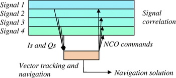
In the vector tracking GNSS architecture (Figure 2), the tracking filters for each signal and the navigation filter are combined into a single estimation algorithm (usually an EKF) [Reference Groves3,Reference Bullock, Kaplan and Hegarty4]. Figure 4 illustrates this. This inputs the Is and Qs from the GNSS baseband signal processor, via a bank of pre-filters, from which it updates the user position, velocity and clock solution. For high dynamics applications, the user acceleration may also be estimated.
Signal correlation and tracking in a vector tracking GNSS architecture.

The NCO commands are generated from predicted pseudo-ranges and pseudo-range rates, calculated from the user position, velocity and clock solution, the satellite positions and velocities and the satellite clock, ionosphere and troposphere corrections.
Note that conventional acquisition and tracking algorithms are required to initialise the vector tracking. Signals from at least four satellites must be tracked before vector tracking can commence. Vector tracking brings a number of benefits. By combining the tracking and navigation filters, it removes a filter cascade, enabling a higher filtering gain to be used stably. Also, where the navigation solution is over-determined (i.e. signals from more than four satellites are used), the tracking of each signal is aided by the others. Both of these properties improve signal to noise performance. Furthermore, vector tracking maintains tracking lock through a single channel outage using the signals from the remaining satellites, provided at least four are tracked. So, if a satellite is temporarily masked, the need to undergo a re-acquisition process when it becomes visible is avoided.
Other names for vector tracking include the vector delay lock loop (VDLL) [Reference Spilker5] and vector frequency lock loop (VFLL) [Reference Pany and Eissfeller6,Reference Kiesel, Held and Trommer7], integrated demodulation and navigation (IDN) [Reference Sennott and Senffner8] and combined navigation and tracking.
1.2. Deep INS/GNSS integration
The architecture of an integrated INS/GNSS navigation system varies in three respects: how corrections are applied to the inertial navigation solution, what types of GNSS measurements are used and how the GNSS user equipment is aided by the INS and integration algorithm [Reference Groves3].
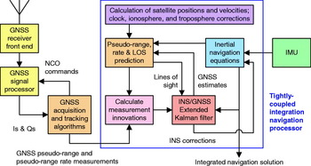
Figure 5 shows a tightly-coupled INS/GNSS integration architecture. This may be thought of as the INS/GNSS equivalent of the conventional GNSS architecture of Figure 1. The GNSS signals are tracked by the GNSS user equipment. The navigation processor inputs pseudo-range and pseudo-range rate measurements from the GNSS user equipment and specific force and angular rate data from the IMU. An inertial navigation solution is obtained by integrating the IMU measurements as described in [Reference Groves3,Reference Titterton and Weston9]. The EKF estimates errors in the inertial navigation solution, IMU outputs and GNSS receiver clock. The inertial navigation solution, corrected by the EKF, then forms the integrated INS/GNSS navigation solution. This is because GNSS measurements are subject to interruption, whereas the inertial navigation solution is continuous.
Tightly-coupled INS/GNSS integration architecture.

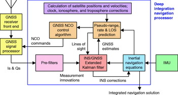
Deep INS/GNSS integration, shown in Figure 6, combines the integration and signal tracking filters into a single estimation algorithm. This is the key distinguishing feature of deeply integrated INS/GNSS, compared to the other integration architectures [Reference Groves3, 10–Reference Soloviev, van Graas and Gunawardena14]. Comparing with Figure 2, it can be seen that deep, sometimes called deeply-coupled or ‘ultra-tightly-coupled’ (UTC), integration is the extension of the stand-alone GNSS vector tracking architecture to an INS/GNSS system.
Deep INS/GNSS integration architecture.

In a deeply integrated architecture, the Is and Qs accumulated from the GNSS receiver correlators are input directly to the navigation processor, instead of being filtered by tracking algorithms first. NCO commands are generated from pseudo-ranges and pseudo-range rates predicted from the inertial navigation solution, receiver clock estimates, satellite positions and velocities and the satellite clock, ionosphere and troposphere corrections.
Deep INS/GNSS integration shares the advantage of GNSS vector tracking. In addition, both inertial aiding of the GNSS code tracking and carrier frequency tracking and variation of the tracking loop bandwidths according to the signal to noise conditions (and degree of INS/IMU calibration) are inherent. Consequently, deeply-coupled integration maximises resistance to interference and sensitivity to weak GNSS signals in a dynamic environment. As with vector tracking, a period of operation under the tightly-coupled architecture, with signals from at least four satellites tracked, is required prior to initialisation.
In both stand-alone GNSS vector tracking (Figure 2) and deep INS/GNSS integration (Figure 6), a bank of pre-filters is used to reduce the flow of measurement data from the GNSS signal processor to the navigation or integration EKF. Two different types of pre-filter may be used: coherent and non-coherent. The coherent design gives higher accuracy, while the non-coherent approach provides greater robustness [Reference Groves, Mather and Macaulay12].
2. DATA LATENCY
Data latency limits the level of dynamics that may be tolerated by a navigation system. Data latency is first discussed for conventional and vector-tracking stand-alone GNSS. This is then extended to deeply integrated INS/GNSS. The effects of data latency on GNSS signal correlation and how they may be compensated in deep INS/GNSS are described. This informs the choice of iteration rates for a GNSS receiver – navigation processor interface.
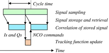
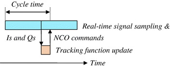
Here, the cycle time is defined as the interval between the start of the correlation interval that generates a set of I and Q measurements and the time at which NCO commands, updated using those I and Q measurements, are first applied in the correlators. A new cycle starts every correlation interval, so successive cycles normally overlap.
2.1. Stand-alone GNSS with independent tracking
In ideal GNSS user equipment, the accumulation outputs from one correlation interval, τa, the Is and Qs, are instantaneously used to update the NCO commands for the next correlation interval. In this case, the cycle time is one correlation period, the minimum possible. In practice, this is only achievable in a receiver, such as a software receiver, where the signal samples after the front-end, but before correlation, may be stored and retrieved. Figure 7 illustrates this.
Lag-less GNSS signal correlation and tracking cycle (using a receiver with signal storage and retrieval capability).

In a conventional real-time GNSS receiver with independent signal tracking, the signal tracking processing load is low, so NCO commands may be updated relatively quickly, provided the GNSS receiver allows NCO command updates in the middle of a correlation interval. Thus the cycle time is just over one correlation period, which has duration τa. Figure 8 illustrates this.
Real-time GNSS signal correlation and tracking cycle with independent signal tracking.

2.2. Stand-alone GNSS with vector tracking
In vector GNSS tracking, the processing load for updating the NCO commands is much higher because the navigation solution must also be updated using an EKF. It can take a full correlation interval (or more) following receipt of the Is and Qs to perform the necessary processing to update the NCO commands.
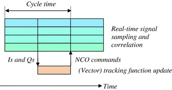
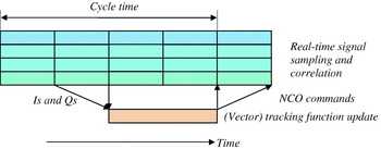
A simultaneous correlation interval for all signals is considered first. This applies where the signals tracked are navigation data-free, the correlation interval is much less than a navigation data message bit or the GNSS receiver does not attempt to synchronise the correlation interval to the navigation data. Where the EKF processing cycle is one correlation interval, the cycle time will be two correlation periods, much greater than for independent signal tracking. Figure 9 illustrates this. In practice, the EKF processing cycle may be longer, further increasing the data latency. If n EKF correlation periods are required to process a full EKF cycle, the cycle time will be 2n EKF correlation periods. Figure 10 illustrates the n EKF=2 case.
Real-time GNSS signal correlation and tracking cycle with vector tracking and simultaneous correlation intervals (n EKF=1).

Real-time GNSS signal correlation and tracking cycle with vector tracking and simultaneous correlation intervals (n EKF=2).

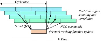
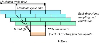
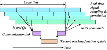
Where the correlation interval for each signal is synchronised with the navigation message bit and the vector tracking EKF processes measurements from all signals simultaneously, an additional lag of a further correlation interval is added (at least for some signals). This is because the system must wait for the I and Q measurements from the latest running correlation channel before it can process those from the earliest running channel. If the NCO commands are applied at the start of a correlation interval, the cycle time is 2n EKF+1 correlation periods, a minimum of three. Figure 11 illustrates this. If the NCO commands are applied on receipt, the cycle time varies from signal to signal between about 2n EKF and 2n EKF+1 correlation periods. Figure 12 illustrates this.
Real-time GNSS signal correlation and tracking cycle with vector tracking, offset correlation intervals and NCO commands applied at the start of the correlation interval (nEKF=1).

Real-time GNSS signal correlation and tracking cycle with vector tracking, offset correlation intervals & NCO commands applied on receipt (nEKF=1).

This additional lag might be reduced by doubling the rate at which correlator output messages are produced, but only including Is and Qs from half the signals in each message. The EKF would then be run with measurements from half of the signals every other cycle and the remaining signals on the alternate cycles. However, the total EKF processing load would be increased.
A further lag is introduced where the vector-tracking navigation processor is external to the GNSS user equipment as it typically takes much longer to pass data over an external data-link than an internal link. If the NCO commands are applied at the start of a correlation interval, the cycle time can be 2n EKF+2 correlation periods, a minimum of four. Figure 13 illustrates this.
Real-time GNSS signal correlation and tracking cycle with vector tracking, offset correlation intervals, communication link and NCO commands applied at the start of the correlation interval (nEKF=1).

Note that the time taken for the NCO commands to respond to dynamics will typically be longer in a poor signal-to-noise environment as the EKF reduces its tracking bandwidths to mitigate noise. Consequently, the dynamics tolerance of the stand-alone GNSS vector tracking is lower in poor signal-to-noise environments than under strong signal-to-noise conditions.
2.3. Deep INS/GNSS integration
In deep INS/GNSS integration, the inertial navigation solution is updated from the IMU measurements and used to calculate the GNSS NCO commands. The INS/GNSS integration EKF then uses the Is and Qs to estimate GNSS and inertial errors. The INS and inertial sensor error estimates impact the NCO commands indirectly via corrections applied to the navigation solution and IMU measurements. The GNSS receiver clock and signal propagation estimates are applied to the NCO commands directly.
Two separate latencies affecting the NCO commands thus apply:
• Updating the NCO commands to reflect user dynamics requires those dynamics to be measured by the IMU, processed by the navigation processor's inertial navigation equations, used to generate NCO commands, transmitted to the GNSS user equipment and applied to the correlators. The latency resulting from this chain is referred to below as dynamics latency.
• Updating the NCO commands to correct for both GNSS and inertial navigation errors is subject to the same latency cycle described in Section 2.2 above because the Is and Qs from the GNSS receiver are used to generate these error estimates. This is referred to as error correction latency.
Deep INS/GNSS integration thus offers a performance benefit over GNSS vector-tracking because an error tracking cycle can generally operate with a lower bandwidth than an error plus dynamics tracking cycle. With a lower tracking bandwidth, sensitivity to noise is decreased, improving robustness under jamming. The error correction latency cycle is identical to the signal tracking latency cycle for stand-alone GNSS using vector tracking. The remainder of this discussion will therefore focus on the dynamics latency.
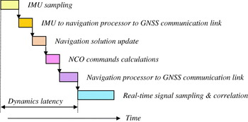
The dynamics latency for deeply-coupled integration is defined here as the interval between the start of the IMU sampling window and the time at which NCO commands, updated using those IMU measurements, are first applied in the correlators. Assuming real-time signal processing, the following factors contribute to the dynamics latency:
• The IMU sampling window, τi;
• The time taken to output the IMU samples to the navigation processor (⩽τi);
• The time taken to update the inertial navigation solution (⩽τi);
• The time taken to update the NCO commands and communicate them to the GNSS user equipment (⩽τa);
• The time taken to apply the NCO commands within the GNSS user equipment (⩽τa), noting that this will vary between signals if the commands are applied at the start of the correlation window.
Figure 14 illustrates this. The total dynamics latency, averaged across signals with different correlation windows, is thus up to 1·5τa+3τi. If the IMU output rate is at least twice the NCO command rate, the maximum average dynamics latency is three GNSS correlation intervals.
Contributors to deep INS/GNSS integration dynamics latency between IMU measurement sampling and their use in controlling the GNSS NCOs.

2.4. Effects of NCO command latency
Consider the stage in the receiver correlation process where the incoming signal has been multiplied by the reference carrier, but has yet to be multiplied by the reference code. The in-phase and quadrature signal samples may be expressed as [Reference Van Dierendonck, Parkinson and Spilker2,Reference Groves3]:

where t sa is the time of signal arrival, δφca is the carrier phase offset between the reference and incoming signal, δf ca is the carrier frequency offset and k is proportional to the signal amplitude and navigation message data bit. Where the code tracking errors are negligible, the prompt outputs of the code correlator, accumulated over the time interval t sa−τa to t sa, may be expressed as:
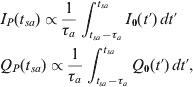
The received power in the prompt channel is then proportional to:

noting that squaring and summing cancels out the effect of the initial carrier phase offset. Where the carrier frequency offset is constant, this simplifies to:
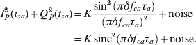
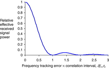
Figure 15 depicts the effective correlated signal power as a function of frequency tracking error. To ensure that the signal power is within a factor of two of the maximum, the condition |δf ca|<0·443/τa must be met. Note that for non-constant frequency tracking errors, equation (3) must be solved numerically. These will occur under line-of-sight acceleration when the receiver constrains the NCO frequencies to be constant during a correlation period. They will also occur under line-of-sight jerk (rate of change of acceleration), regardless of the GNSS receiver and navigation processor design.
Effect of frequency tracking error on effective received signal power.

NCO command latency also has an impact on code tracking; however this is much less than its impact on carrier tracking.
For GNSS vector tracking, where the user acceleration is estimated by the EKF, it may be used to compensate the NCO commands for the time lag between the measurements used to calculate them and their application within the GNSS receiver correlation channels. The cycle time, τc, acts to limit the carrier frequency tracking and code tracking bandwidths to a maximum of 1/2τc. With a cycle time of at least two EKF processing intervals (see Section 2.2), the maximum tracking bandwidth is less than a quarter of the EKF and interface iteration rate. Where the vector-tracking EKF estimates acceleration, the dynamics tolerance will be similar to that of a conventional second-order carrier frequency tracking loop. Therefore, from [Reference Van Dierendonck, Parkinson and Spilker2,Reference Groves3], with a correlation interval, τa, of 20 ms, a line-of-sight jerk of up to 370 m s−3 can be tolerated with a 5 Hz frequency tracking bandwidth at the L1 frequency before carrier phase interference drops the effective power by a factor of two (see equation (4)).
For deep INS/GNSS integration, the above discussion only applies to error correction latency. However, the errors estimated in the deeply integrated EKF are not subject to the same rapid changes as the navigation states estimated in a GNSS vector-tracking EKF. Consequently, lower bandwidths may be implemented without introducing jerk vulnerability.
Dynamics tolerance in deep INS/GNSS integration is poorest where only the velocity solution at the end of the IMU sampling interval is used to generate the NCO commands. If the dynamics latency is two 20 ms correlation intervals, the maximum tolerable line-of-sight acceleration is about 100 m s−2 (assuming a 4 m s−1 maximum pseudo-range rate error).
However, in a well designed system, the inertial acceleration solution will be used to estimate the line-of-sight acceleration and then used to predict forward the NCO commands to the time they are applied within the receiver. These computations may be made within either the navigation processor or the GNSS user equipment and are recommended for use in all deep INS/GNSS implementations. Then, under constant acceleration, it is the difference between the actual and estimated dynamics latencies that determines the dynamics tolerance. Thus, if the data latency is known to within 1 ms, the maximum tolerable line-of-sight acceleration for a 20 ms correlation interval will be about 4000 m s−2, noting that larger accelerations can be tolerated where the correlation interval is shorter. However, the system is still vulnerable to jerk.
As in any INS/GNSS system (or any estimator), uncompensated data latency between one measurement stream (inertial) and the other (GNSS) can bias the EKF estimates if not compensated. Latency compensation techniques include lagging the faster responding stream to match the slower stream and weighting down the measurements [Reference Groves3].
In a basic deep INS/GNSS implementation, the assumption is made that the NCO commands supplied by the navigation processor are correct. However, this may be invalidated by dynamics occurring between the IMU sampling interval and the application of the NCO commands within the GNSS receiver using that IMU data. However, once the Is and Qs from the relevant correction interval become available, further IMU measurements will have been input by the navigation processor. These may be used to apply dynamic latency corrections to the GNSS measurements input to the INS/GNSS EKF, thus preventing the dynamics latency from biasing the state estimates. Further investigation is needed to determine which applications would benefit from this. Note that dynamic latency corrections cannot be applied in stand-alone GNSS vector tracking as no information is available from which to generate them.
3. INTERFACE ITERATION RATE ANALYSIS
Iteration rate requirements for the navigation processor – GNSS receiver interface depend on the user dynamics (and receiver clock drift), the GNSS receiver design and the navigation processor design, particularly the application of latency corrections. The iteration rate of the interface must be sufficient to limit the frequency tracking error as discussed in Section 2.4 above. To determine suitable rates at which NCO commands should be output by the navigation processor, six data latency scenarios are considered. The first three consider a constant line-of-sight acceleration, while the latter three involve jerk.
In case 1, the acceleration and the correlator control latencies are known and the latencies are compensated as far as possible by either the navigation processor or the GNSS user equipment. However, the NCO frequencies are constrained to be constant over the correlation window. Therefore, the NCO frequency is set so that the mean frequency error over the correlation window is zero. Consequently, to limit the effect of phase interference over the correlation window such that the effective signal power is dropped by no more than a factor of two (see equation (3)), the following condition must be met:

where a LOS is the line-of-sight acceleration (including receiver clock “acceleration”) and λca is the carrier wavelength. An approximate solution may be obtained by converting the cosine function to a power series expansion, integrating and truncating to fourth order in t, giving a quadratic equation in a LOSτa2/λca, of which the smaller solution applies. Thus:

Cases 2 and 3 assume that no latency compensation is applied. Therefore the NCO frequency is set to a value that was correct at some point prior to the start of the correlation window. In case 2, it is assumed that the NCO commands were correct one correlation interval prior to the start of the correlation window, whereas in case 3, it is assumed that the NCO commands were correct two correlation intervals before the start of the correlation window. To limit the effect of phase interference such that the effective signal power is dropped by no more than a factor of two, the following conditions must be met for cases 2 and 3, respectively:


Solving these using the same method as described for case 1 gives:


In cases 4, 5 and 6, it is assumed that the acceleration and correlator control latency are known and used to compensate the latency. Furthermore, it assumed that the NCO frequencies may be varied over the correlation window. Assuming the latency is known to within 1 ms, the maximum acceleration that can be tolerated without dropping the effective signal power by more than a factor of two is, from equation (4), 443 s−1λca/τa, giving a large acceleration tolerance. However, the systems are still vulnerable to jerk.
It is assumed that vector GNSS tracking does not track jerk because conventional GNSS tracking loops cannot track jerk. In the deeply integrated case, the IMU measurements may, in principle, be used to estimate line-of-sight jerk and to predict changes in acceleration over the latency interval and correlation window. However, this has not been reported in the literature on deeply integrated INS/GNSS, while vibration may severely limit its effectiveness. Therefore, no jerk prediction is included in cases 4, 5 and 6.
All three cases assume there is a constant jerk. The estimated line-of-sight acceleration is assumed to be correct one correlation interval prior to the start of the correlation window in case 4, two correlation intervals in case 5 and five correlation intervals in case 6. Thus, to limit the effect of phase interference over the correlation window such that the effective signal power is dropped by no more than a factor of 2, the following conditions must be met for cases 4, 5 and 6, respectively:



where j LOS is the line-of-sight jerk. Again, an approximate solution may be obtained by converting the cosine function to a power series expansion, integrating and truncating to sixth order in t, giving a quadratic equation in j LOSτa3/λca, of which the smaller solution applies. Thus



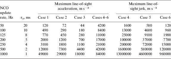
Table 1 gives the maximum line-of-sight acceleration for all six cases, and the maximum line-of-sight jerk for cases 4 to 6 for a range of NCO command update rates. As can be seen, the required update rate depends on both the level of dynamics and the degree of latency compensation applied.
Maximum line-of-sight acceleration and jerk for a range of NCO update rates and NCO command lag scenarios (GPS L1 band)
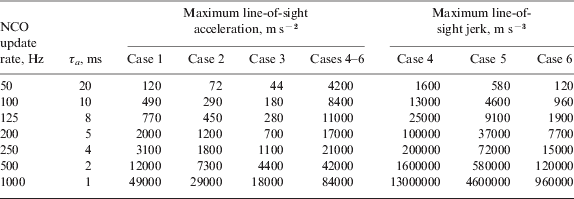
For the majority of applications, the acceleration will be within 100 m s−2 and the jerk within 100 m s−3, so an NCO command update rate of 50 Hz should be adequate provided latency compensation is applied. Otherwise a 100 Hz update rate is needed.
However, there are cases where a higher update rate will be required. One is applications involving extreme dynamics. The other is high-vibration environments. For example, a 74 Hz sinusoidal oscillation of amplitude 0·01 m will have an acceleration amplitude of 2160 m s−2 and a jerk amplitude of ~106 m s−3. However, oscillatory jerk is not expected to cause loss of tracking where the position amplitude is much less than a carrier wavelength.
For GNSS vector tracking, high jerks may be tolerated by using very high carrier tracking bandwidths. These, in turn, require high correlator output rates. As discussed in Section 2.4, the maximum carrier frequency tracking bandwidth is about a quarter of the correlator output rate. The acceleration tracking bandwidth will typically be lower than the velocity/frequency tracking bandwidth, so the line-of-sight acceleration estimates will exhibit greater lag. Consequently, the case 6 interface tolerances in Table 1, whereby the acceleration estimates are five correlation periods out of date, are likely to be closest to the true maximum jerk.
However, very high-bandwidth vector tracking is likely to cause severe processor loading problems. An alternative is to make use of the pre-filter estimates in the GNSS NCO control algorithm. This would produce an architecture which combined low frequency vector tracking with high-frequency independent tracking. A further problem is that increasing the tracking bandwidth to handle dynamics reduces the signal-to-noise sensitivity. For example, with a 250 Hz carrier frequency tracking bandwidth and 1 ms signal correlation interval, the minimum sustainable C/N 0 is ~30 dB-Hz.
For deep INS/GNSS integration, the acceleration latency is determined by the IMU update rate, not the tracking bandwidth. The acceleration obtained from a set of IMU measurements will be the average value over the IMU sampling interval, and so may be thought of as applying to the middle of the sampling interval. As discussed in Section 2.3, the lag between the end of the IMU sampling interval and the application of the corresponding NCO commands within the GNSS receiver will depend on the relative phasing of the IMU and GNSS interfaces, which may vary over time. If the IMU output rate is twice the NCO command rate, the acceleration lag will be between 0·25 and 3·25 GNSS correlation intervals. This gives a jerk tolerance between those given by cases 4 and 5 in Table 1. Comparing the case 4 and case 5 columns in Table 1, it can be seen that a 0·75 correlation period drop in the acceleration lag has a similar impact to doubling the NCO update rate. Therefore, increasing the NCO update rate above half the IMU output rate brings little benefit in jerk tolerance.
Thus, deep INS/GNSS integration brings much greater tolerance of high jerk environments than stand-alone vector GNSS tracking. Furthermore, there is no need to use a high signal tracking bandwidth (provided the lever arm between the IMU and the GNSS antenna is well calibrated). Thus, a deeply-coupled architecture can potentially tolerate high dynamics and poor GNSS signal to noise simultaneously.
4. INTERFACE STANDARDISATION
Deep INS/GNSS integration requires interoperability of IMUs and GNSS receivers produced by different manufacturers. Consequently, the development of a standard interface for the GNSS receiver to output I & Q measurements to the navigation processor and input NCO commands is highly desirable. Such an interface would also be useful for vector tracking. An obstacle to standardisation is that different GNSS receivers implement very different designs. Differences include, but are not limited to:
• Which constellations and signal types are used;
• The length of the correlation periods and how they are synchronised between signals and with the navigation data message bits;
• Whether separate early and late or early minus late correlation channels are used;
• What degree of NCO control is accepted and when the NCO commands are applied;
• How binary offset code (BOC) signals, such as the GPS M code, are correlated;
• How signals with time division multiplex (TDM) of the data-modulated and pilot components, such as GPS M code and GPS L2C, are correlated;
• General timing and data latency issues.
Consequently, the interface design needs to be as flexible as possible. It is a lot easier to adapt an interface to a receiver design than a receiver design to an interface. Therefore, an inflexible interface will not be adopted as an industry standard.
Ideally, a deep INS/GNSS integration interface would support a plug and play capability, enabling a navigation processor to operate with more than one GNSS user equipment design without the need to manually re-configure the user equipment software, the navigation processor software or both. Furthermore, interface protocols should be designed to support future expandability. Consequently, any interface protocol must support exchange of configuration information between receiver and navigation processor so that each knows which features the other supports.
The correlator output message format must be compatible with as many different GNSS receiver designs as possible. It must also be efficient. Therefore, repetition rates should not be excessive and data-link capacity should not be wasted transmitting null outputs where the format specifies information that a particular receiver does not provide. Therefore, each correlator output message should comprise three components:
• A header, common to all signals;
• One or more signal data specification blocks;
• A block of correlator output data for each signal.
The header should contain overall timing information and indicate how many specification and output data blocks follow. The specification blocks should comprise all the information required to decode the correlator output data for each signal, including signal-specific timing, correlator number and spacing, BOC correlation information and data-bit edge location (where appropriate). Each specification block should be repeated every second or so; it need not be included in every correlator output message.
The correlator output data blocks should comprise the Is and Qs for every signal tracked. The number of bits required for each correlator output may be reduced to eight by transmitting a scaling factor common to all Is and Qs from a given signal.
The lag between the time of validity of NCO commands and their application is required by the navigation processor for latency compensation. This lag will vary from signal to signal in receivers that align the correlation windows with the navigation message data bits. A further complication is that the lags may not be constant. Therefore, the correlator output block for each signal should include some form of NCO command identification and an offset time if a new NCO command was applied midway through the correlation interval. Signal identification words should be used to match the specification blocks to the data blocks and also for identifying the NCO commands from the navigation processor.
The minimum NCO commands that the navigation processor must output to the GNSS receiver are code and carrier NCO frequency commands for each signal tracked, noting that it is more efficient to transmit Doppler shifts than absolute frequencies. In addition, the navigation processor must be able to switch receiver correlation channels between external and internal control on a signal-by-signal basis. This is to allow re-acquisition of lost signals and acquisition of new signals as satellites rise without having to revert the whole navigation system to conventional signal tracking.
The maximum speed of the space shuttle is 8 500 m s−1, while GNSS satellite speeds are around 1000 m s−1. Consequently, the NCO command interface must support line-of-sight velocities up to 10 000 m s−1. Sufficiently small quantisation levels may be obtained with 16 bits per sample, provided each quantisation residual is fed forward to correct the next NCO command prior to quantisation.
The interface standard should allow for successive NCO command messages to include data for different signals. This should reduce data lags in cases where the GNSS receiver implements different correlation periods for different signals to align with the navigation message data bits and is more efficient than transmitting NCO commands at a faster rate than the receiver implements them.
A basic NCO command interface constrains the NCO frequencies to take constant values between command updates. This will result in suboptimal signal correlation when the user antenna is accelerating. In the deeply integrated INS/GNSS case, the acceleration will be known (albeit lagged). Therefore, there should be an option to improve the signal correlation by transmitting NCO ‘acceleration’ commands in the form of Doppler shift rates of change.
Other optional navigation processor outputs that the interface standard should support include:
• Code and carrier phase jump commands;
• Sub-carrier NCO commands for receivers that track BOC signals using a double estimator architecture [Reference Hodgart, Blunt and Unwin15];
• Acquisition control and aiding information.
Lastly, to aid development, debugging and testing, there should be a capability for the GNSS receiver to both echo back NCO commands from the navigation processor when they area applied and output internally-generated NCO commands.
CONCLUSIONS
Data latency has been analysed for a range of different stand-alone GNSS vector tracking and deep INS/GNSS integration architectures. Suitable latency compensation techniques have been identified. It has been shown that, for the majority of applications, an NCO command update rate of 50 Hz with latency compensation and 100 Hz without is sufficient. An approach to interface standardisation which can handle a wide range of different GNSS signals and receiver designs has been proposed.
ACKNOWLEDGEMENT
This work was funded by the AIRS2P2 Integrated Project Team of the UK Ministry of Defence (MoD). The views expressed herein are those of the authors and do not necessarily reflect those of MoD.