

Introduction
Cochlear implant devices can deliver sound to deaf children by electrically stimulating the auditory nerve. It is reasonable to assume that these children require stable input from their cochlear implant devices to ensure optimal conditions for developing hearing, speech and language skills. Therefore, monitoring the integrity of both the external equipment and internal electrode array of the cochlear implant is important. While external equipment is easily tested and repaired if necessary, the internal implanted component is less accessible.
The implant telemetry system is now routinely used in the clinic to assess the integrity of the internal electrode array by measuring electrode impedances, electrically evoked compound action potentials and electrically evoked stapedial reflex thresholds. Stimulation parameters measured using telemetry systems can help ensure the safety and reliability of the implants, enable control of power consumption requirements, and help determine appropriate coding strategies.Reference Zilberman and Santogrossi 1 Obtaining behavioural responses to stimulation can also indicate integrity, stability and fidelity of stimulation, and influence device programming and access to adequate sound.
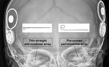
Several types of electrode arrays have been developed. In general, two types of electrodes are routinely used in children: (1) a straight array that resides laterally (anti-modiolar) in the scala tympani (Figure 1, left array); and (2) a pre-curved array that resides in a peri-modiolar position (Figure 1, right device).
X-ray of a child who received the two different electrode arrays in the same surgery: a thin, straight anti-modiolar CI422 electrode array in one ear (left) and a pre-curved peri-modiolar CI24RE electrode array in the other ear (right).

The advantages and disadvantages of electrode placement within the cochlea is a topic of debate based in a mix of theory, opinion and evidence. Historically, there was a shift to using peri-modiolar arrays because of their proximity to the spiral ganglion, possibly creating more efficient transmission of current, and consequently improving outcomes.Reference Gordin, Papsin, James and Gordon 2 , Reference Shepherd, Hatsushika and Clark 3 Studies comparing older generations of these two types of arrays across participants revealed significantly greater impedance for the peri-modiolar array, and lower levels of current were required to elicit a behavioural response (T-level) or to be judged as comfortably loud (C-level).Reference Gordin, Papsin, James and Gordon 2 , Reference Saunders, Cohen, Aschendorff, Shapiro, Knight and Stecker 4 – Reference van Wermeskerken, van Olphen and Smoorenburg 6 This was felt to be a factor in rendering better speech performance.Reference Bacciu, Pasanisi, Vincenti, Guida, Barbot and Berghenti 7 The impedance differences measured between these electrodes were most pronounced in the basal region of the cochlea, and were attributable to electrode surface area differences instead of differential fibrous growth.Reference Saunders, Cohen, Aschendorff, Shapiro, Knight and Stecker 4 , Reference Busby, Plant and Whitford 5 Recent evidence suggests that modiolar distance from the electrode minimally affects impedance-based stimulation levels.Reference Davis, Zhang, Gifford, Dawant, Labadie and Noble 8 Furthermore, migration following implantation occurred less often with peri-modiolar than anti-modiolar arrays.Reference Dietz, Wennström, Lehtimäki, Löppönen and Valtonen 9
While advantageous for a lower current, a peri-modiolar array may be destructive to the remaining cochlear structure.Reference Briggs, Tykocinski, Saunders, Hellier, Dahm and Pyman 10 In an age of expanding cochlear implantation criteria that includes individuals with residual hearing, a thinner, straight anti-modiolar array (i.e. model CI422 from Cochlear Corporation, Melbourne, Australia) has been developed in an effort to theoretically preserve cochlear structure and residual hearing. A round window approach to inserting newer, straight, slim arrays has also been proposed to aid in cochlear preservation compared to the cochleostomy approach,Reference Adunka, Gstoettner, Hambek, Unkelbach, Radeloff and Kiefer 11 , Reference Adunka, Unkelbach, Mack, Hambek, Gstoettner and Kiefer 12 although both approaches can successfully limit intra-cochlear trauma with a cochleostomy site inferior to the round window.Reference Briggs, Tykocinski, Xu, Risi, Svehla and Cowan 13 , Reference Briggs, Tykocinski, Stidham and Roberson 14 While new, slim anti-modiolar arrays are potentially advantageous to cochlear preservation, these arrays may still require higher current levels to elicit behavioural responses, and may continue to be more susceptible to migration following implantation than peri-modiolar arrays.Reference Dietz, Wennström, Lehtimäki, Löppönen and Valtonen 9
Children who receive implants at an early age rely on consistent input for auditory, speech and language development. It is therefore important to assess both the integrity of this new array and outcomes of different surgical approaches prior to exclusively using this array during bilateral implantation in children. Preliminary results comparing speech perception abilities of adults implanted with either the peri-modiolar CI24RE array or anti-modiolar CI422 array suggest no differences between the arrays in both quiet and noise conditions for up to nine months post-activation.Reference Doshi, Johnson, Mawman, Green, Bruce and Freeman 15 Two groups of children who received either the peri-modiolar CI24RE array via cochleostomy or anti-modiolar CI422 array via the round window revealed higher impedances at apical electrodes, but higher electrically evoked compound action potential thresholds at basal electrodes for the anti-modiolar versus peri-modiolar array.Reference Telmesani and Said 16 However, contributions of electrode size or surgical approach to group differences were not considered; furthermore, other stimulation parameters important to clinical programming were not investigated.
Given the concerns regarding surgical approach and modiolar proximity, and previously documented differences between types of arrays, this study aimed to: (1) evaluate whether this new, straight anti-modiolar array works as efficiently and reliably as the pre-curved peri-modiolar array; (2) quantify any differences in programming requirements; and (3) identify whether surgical approach affects the stimulation parameters for this new array. In order to isolate array differences from other factors introduced in between-group comparisons, the two arrays were implanted simultaneously and compared within the same child.
Materials and methods
Participants
A prospective, mixed repeated measures study was carried out on 64 children who qualified for simultaneous bilateral cochlear implantation and whose parents had provided informed consent. These children were implanted at age 0.8 to 18.0 years (mean ± standard deviation = 3.8 ± 4.5 years) with two electrode arrays from Cochlear Corporation: the pre-curved peri-modiolar Freedom Contour Advance (CI24RE) array in one ear and the thin, straight anti-modiolar (CI422) array in the other ear. The order of implantation and the ear receiving each electrode array were randomised.
All 22 intra-cochlear electrodes of both arrays were fully inserted in all children. Our preferred insertion depth for the anti-modiolar electrode was between 21 and 23 mm in an otherwise normal cochlea. This prevents the most distal electrode contacts from sitting within the bony cochleostomy, and prevents buckling of the electrode array known to occur with over-insertion.Reference Hassepass, Aschendorff, Bulla, Arndt, Maier and Laszig 17
Of the 64 children, 37 (57.8 per cent) were female. Forty-one children (64.1 per cent) received the anti-modiolar array in the left ear.
The hearing loss was congenital in 46 children (71.9 per cent), progressive in 16 (25.0 per cent) and sudden in 2 (3.1 per cent). Aetiology of hearing loss included: auditory neuropathy spectrum disorder, in four children (6.3 per cent); congenital cytomegalovirus, in three (4.7 per cent); and cochleovestibular abnormality (e.g. enlarged vestibular aqueduct, incomplete partition type 2), in nine (14.1 per cent). Six children (9.4 per cent) who remained undiagnosed had a family history of hearing loss. The hearing loss was genetic (e.g. GJB2 mutation) in six children (9.4 per cent) and a result of bacterial meningitis in one child (1.6 per cent). Another six children (9.4 per cent) who remained undiagnosed had significant risk factor(s) (e.g. hypoxic ischaemic encephalopathy). The cause of hearing loss was unknown in 29 children (45.3 per cent).
A cochleostomy approach was used for the first cohort of 43 children (67.2 per cent) (from August 2012 to December 2013), and a round window approach was used for the anti-modiolar array in the second cohort of 21 children (32.8 per cent) (January 2014 to August 2014).
Age of implantation and graded profile analysis scoresReference Daya, Figueirido, Gordon, Twitchell, Gysin and Papsin 18 , Reference MacDonald, Sohn, Papsin and Gordon 19 (out of 13, with higher numbers indicating fewer implantation concerns) were similar, regardless of: the ear implanted with the anti-modiolar array (age of cochlear implant surgery, t (35.6) = −1.5, p = 0.14; graded profile analysis, t (26.2) = 1.0, p = 0.31); surgical approach (age of cochlear implant surgery, t (60.1) = 0.4, p = 0.65; graded profile analysis, t (55) = 0.7, p = 0.50); or sex (graded profile analysis, t (55) = −0.8, p = 0.45), with the exception that males tended to be implanted at a younger age (2.6 ± 2.0 vs 4.7 ± 5.5 years; t (48.3) = 2.2, p = 0.04).
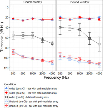
On average, both unaided (F (1.7, 41.5) = 11.0, p < 0.001) and bilateral aided (F (1.7, 19.8) = 9.8, p = 0.002) pre-implantation audiometric thresholds were better in the low frequencies, and sloped to worse thresholds in the high frequencies (Figure 2, open symbols). However, there were no differences between the ears (unaided, F (1, 24) = 1.5, p = 0.23), or group differences for: surgical approach (unaided, F (1, 24) = 1.6, p = 0.22; aided, F (1, 12) = 0.3, p = 0.67), gender (unaided, F (1, 24) = 0.88, p = 0.36; aided, F (1, 12) = 0.2, p = 0.68) or ear implanted with the anti-modiolar array (unaided, F (1, 24) = 0.06, p = 0.81; aided, F (1, 12) = 0.1, p = 0.43).
Mean audiometric thresholds for ears implanted with the peri-modiolar array (blue triangles) and anti-modiolar array (red circles), both pre-implantation (open symbols) and post-implantation (filled symbols). Pre-implantation aided thresholds (black open squares) were collected while children wore bilateral hearing aids. CI = cochlear implant

Surgical approach
In all cases, the round window was adequately visualised by removal of the bony round window niche. Bony cochleostomy was performed anterior and inferior to the round window membrane in order to facilitate electrode placement within the scala tympani. The cochlear endosteum was exposed and the cochlea was entered using a McGee rasp. Round window insertion was performed after a small slit was created using a Rosen needle. The peri-modiolar array was inserted using a standard advance off-stylet technique. The anti-modiolar array was inserted until resistance to further insertion was felt. Temporalis fascia was utilised to seal both the bony and round window openings around the electrode array. In order to prevent array extrusion, the peri-modiolar array was fixed in place to the incudal buttress using a size 7.0 Prolene® suture.
Outcome measures
Parameters of electrode impedance, stimulation thresholds (T-levels), comfortably loud current levels (C-levels) and thresholds for eliciting electrically evoked compound action potentials were collected from children's cochlear implant program settings, or maps, created during four time points within the first 3 months of cochlear implant use: at cochlear implant activation/day 1, week 1, month 1 and month 3. Impedances, electrically evoked compound action potentials and electrically evoked stapedial reflex thresholds were also collected at the time of surgical insertion.
Speech perception assessment was conducted, using age-appropriate tests, in quiet conditions, for each ear and bilaterally after six months of cochlear implant use. Stimuli were presented in a sound-treated booth at 0-degree azimuth.
Repeated measures analyses of variance were conducted, with array, time and electrode as within-subject factors, and surgical approach for the anti-modiolar array as a between-subject factor. The ear implanted with the anti-modiolar array could not be tested as a between-subject factor, as there were insufficient numbers for the left and right ears in the round window approach group. Greenhouse-Geisser corrections for sphericity were used when indicated. Bonferroni corrections were used in pairwise comparisons and post-hoc testing.
Not all children attended each appointment. In addition, both arrays were not always tested at each appointment because of patient compliance and/or time limitations. As such, 27 out of 43 (63 per cent) of the cochleostomy group and 10 out of 21 (48 per cent) of the round window group had complete datasets and could be included in the repeated measures analyses.
Ethical standards
All procedures contributing to this work complied with the ethical standards of the Hospital for Sick Children's Research Ethics Board and the Helsinki Declaration of 1975 (as revised in 2008).
Results
Impedance and compliance
Impedance and compliance stabilised within a month for both arrays, as described below.
Monopolar 1 + 2 impedance
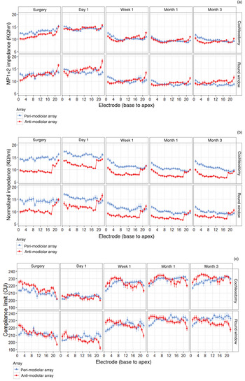
Both arrays had a similar number of open electrodes (chi-square (1) = 0.77, p = 0.38); further details are provided in Appendix 1. All impedance effects were similar between common ground mode and monopolar 1 + 2 mode. To avoid redundancy, only monopolar 1 + 2 impedance outcomes are reported (Figure 3a, b) as this mode was used to calculate electrode compliance (Figure 3c).
Stability of (a) measured monopolar (MP) 1 + 2 impedance, (b) normalised impedance to an average electrode surface area (0.2 mm2), and (c) compliance limit, across time and between the peri-modiolar array (blue triangles) and anti-modiolar array (red circles), using either a cochleostomy or round window approach for implanting the anti-modiolar array. CU = current units. Continued on following page.

Impedance changed significantly over time (F (2.6, 90.2) = 173.5, p < 0.001) (Figure 3a), with increases during the time between surgery and activation (p < 0.001), particularly for the anti-modiolar array (F (1.5, 54.0) = 3.7, p = 0.043). There was a non-significant (p = 0.43) trend of lower impedance for the anti-modiolar array immediately following insertion through cochleostomy. For both arrays, impedance quickly reduced over the first week of activation (p < 0.001) and stabilised after a month of stimulation (p = 1.0).
There was a differential effect of surgical approach on impedance (F (1, 35) = 8.9, p = 0.005), whereby overall impedance for the anti-modiolar array tended to be 0.7 ± 0.4 kΩ higher with a round window versus cochleostomy approach (p = 0.06). Impedance also significantly varied across electrodes between the two arrays (F (8.4, 294.0) = 6.1, p < 0.001). When collapsed across time, impedance was greater for the peri-modiolar array in basal electrodes (numbers 1–4, p < 0.05), but greater for the anti-modiolar array in apical electrodes (numbers 21 and 22, p < 0.05).
As the electrodes in the two arrays differed in terms of geometric surface area (anti-modiolar = 0.14–0.20 mm2; peri-modiolar = 0.21–0.23 mm2), impedance was first calculated per surface area (impedance × surface area; kΩ × mmReference Gordin, Papsin, James and Gordon 2 ) and then normalised (Figure 3b) to the average surface area across all electrodes of both arrays (0.2 mm2). The anti-modiolar array was designed to be thinner, with smaller active electrodes. Consequently, normalised impedance was significantly greater for the peri-modiolar array (F (1, 35) = 76.5, p < 0.001) for all but apical electrodes (numbers 19–22, p > 0.05).
Similar to uncorrected impedance, normalised values changed over time (F (2.5, 89.1) = 162.7, p < 0.001) and stabilised after a month of stimulation (p = 1.0), and array differences were greatest at earlier time points (F (1.7, 60.0) = 4.3, p = 0.023).
Contrary to uncorrected values, there was no significant difference in normalised impedance between surgical approaches for the anti-modiolar array (F (1, 35) = 2.7, p = 0.11).
Two additional metrics were used to quantify variation in impedance within the array and across time, the details of which are provided in Appendix 1. Briefly, variation in impedance across electrode and time was similar for both arrays.
Compliance limit
Compliance limit (in current units) was calculated as: 5 × ((natural logarithm ((10 000 / monopolar 1 + 2 impedance) / 15.989) / 0.0903) − 1).
As with impedance, maximum compliance changed significantly over time (F (2.6, 90.5) = 144.6, p < 0.001); however, as expected given the relationship between compliance and impedance, the compliance limit changed in the opposite direction to impedance (Figure 3b). Compliance limit for both arrays decreased between surgery and cochlear implant activation (p < 0.001), then quickly increased over the first week of activation (p < 0.001) and stabilised within a month of stimulation (p = 1.0).
The anti-modiolar array compliance limits tended to be lower during activation (p < 0.001). Compliance limits also significantly varied across electrodes between the two arrays (F (7.2, 255.3) = 5.1, p < 0.001). Commensurate with, but opposite to, measured impedance, compliance limits were greater for the anti-modiolar array in basal electrodes (numbers 1–5, p < 0.05), but greater for the peri-modiolar array in apical electrodes (numbers 20–22, p < 0.05). There was no impact of surgical approach (round window vs cochleostomy) on the compliance limit for the anti-modiolar array (p = 0.07).
Responses to electrical stimulation
Threshold and comfortable loudness levels
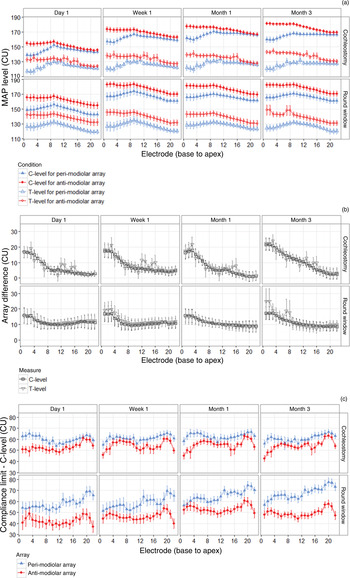
Clinically, C-levels for paediatric patients were set relative to T-levels. As such, outcomes were similar for T- and C-levels (Figure 4a, b). Regardless of surgical approach for the anti-modiolar array (T-level, F (1, 32) = 0.4, p = 0.54; C-level, F (1, 32) = 0.5, p = 0.50), higher current levels were required to elicit behavioural responses (T-level, 12.9 ± 2.0 current units) and set C-levels (11.9 ± 2.0 current units) with the anti-modiolar versus peri-modiolar arrays (T-level, F (1, 32) = 40.2, p < 0.001; C-level, F (1, 32) = 33.6, p < 0.001), especially in basal (number 3 – T-level, 22.6 ± 4.7 current units; C-level, 19.4 ± 4.3 current units) versus apical (number 20 – T-level, 7.7 ± 2.8 current units; C-level, 7.4 ± 2.6 current units) electrodes (T-level, F (3.4, 109.5) = 3.4, p = 0.015; C-level, F (1.3, 42.1) = 5.0, p = 0.02).
Array differences in parameters used by clinicians in the children's cochlear implant program settings (maps). (a) Threshold levels (T-levels; open symbols) and comfort levels (C-levels; filled symbols) by electrode and over time for the peri-modiolar array (blue triangles) and anti-modiolar array (red circles) in children who received the anti-modiolar array using a cochleostomy or round window approach. (b) Differences between the two arrays for both C-levels (squares) and T-levels (inverted triangles) across electrodes, over time and between groups. (c) Differences between compliance limit and C-level (headroom) for the peri-modiolar array (blue triangles) and anti-modiolar array (red circles). CU = current units. Continued on following page.

The significant increase in C-level with time (F (1.8, 59.3) = 140.0, p < 0.001), particularly within the first week (p < 0.001), reflected the incremental increase in stimulation provided in clinically determined cochlear implant program settings (maps) for the children. These array differences by electrode were further highlighted (Figure 4b) by plotting the differences across array and measure (T- and C-levels). The degree of difference for each electrode was similar for each measure (F (1, 40) = 2.0, p = 0.17) and approach (F (1, 40) = 0.20, p = 0.66).
Both compliance limits and C-levels were higher for the anti-modiolar array at different electrodes, but by different amounts (2.1 ± 1.1 current units vs 11.9 ± 2.0 current units, respectively). Therefore, to determine how close the C-levels approach maximum compliance (‘headroom’), the difference between these two measures was calculated (Figure 4c). Overall, the anti-modiolar array had 14.0 ± 2.0 current units less headroom (i.e. less difference between compliance limit and C-level) than the peri-modiolar array (F (1, 32) = 46.3, p < 0.001). Furthermore, this difference between arrays widened (worsened) by on average 9.0 ± 4.7 current units when the round window approach was used (F (1, 32) = 6.0, p = 0.02), particularly at apical electrodes (F (5.4, 173.5) = 2.3, p = 0.04). Headroom gradually increased, or C-levels were further from compliance limits, over time (F (2.2, 70.4) = 3.2, p = 0.04), with the greatest increase occurring within the first week (p = 0.046).
Evoked responses
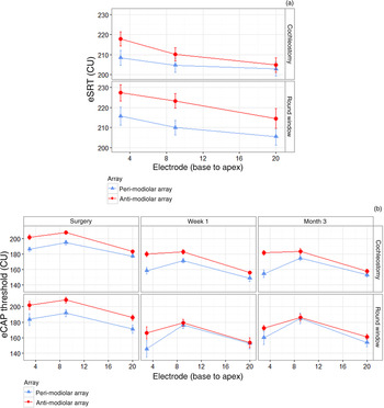
Current levels for electrically evoked stapedial reflex thresholds (Figure 5a) were significantly higher for the anti-modiolar array (F (1, 58) = 11.0, p = 0.002) across all electrodes (F (1.6, 93.8) = 0.6, p = 0.52) and regardless of surgical approach for the anti-modiolar array current (F (1, 58) = 1.0, p = 0.31). Current levels for electrically evoked stapedial reflex thresholds also significantly differed across both arrays (F (1.7, 98.4) = 27.2, p < 0.001), with progressively higher current levels required towards basal electrodes (p < 0.01).
Evoked responses for the peri-modiolar array (blue triangles) and anti-modiolar array (red circles) in children who received the anti-modiolar array via cochleostomy or round window approach. (a) Electrically evoked stapedial reflex thresholds (eSRT) measured at three electrodes during surgery. (b) Electrically evoked compound action potential (eCAP) thresholds measured at three electrodes during surgery, and after one week and three months of implant use. CU = current units

Threshold current levels for electrically evoked compound action potentials (Figure 5b) also significantly differed with electrode (F (2, 22) = 11.3, p < 0.001) and time (F (2, 22) = 111.7, p < 0.001). In particular, electrically evoked compound action potential thresholds decreased after surgery (p < 0.001) and stabilised within one week (p = 0.27), and electrically evoked compound action potential thresholds for an apical electrode (number 20) were greater (p < 0.001) than a mid-array electrode (number 9), which were both similar (p = 0.10) to a basal electrode (number 3). Although the overall array difference in electrically evoked compound action potential thresholds of 10.7 ± 3.6 current units was not significant (F (1, 11) = 3.5, p = 0.09), array differences significantly decreased from base to apex (F (2, 22) = 5.3, p = 0.013), such that there was only a significant difference of 15.5 ± 4.7 current units at basal electrode 3 (p = 0.007).
Evoked compound action potential thresholds as predictors of behavioural thresholds
Electrically evoked compound action potential thresholds weakly predicted behavioural thresholds to stimulation for both arrays, as described below.
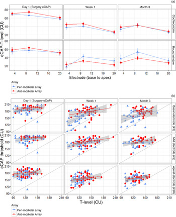
Differences between electrically evoked compound action potential thresholds and T-levels (Figure 6a) were not significantly different between the two arrays (F (1, 9) = 0.6, p = 0.45), but significantly differed across electrode (F (2, 18) = 4.1, p = 0.03) and time (F (2, 18) = 41.8, p < 0.001). Specific differences are described in Appendix 1.
Relationship between electrically evoked compound action potential thresholds and behavioural thresholds to stimulation (T-levels) for the peri-modiolar array (blue triangles) and anti-modiolar array (red circles) across time. Day 1 T-levels were used in conjunction with electrically evoked compound action potentials thresholds obtained during surgery. (a) Differences between electrically evoked compound action potential thresholds and T-levels at three electrodes in children who received the anti-modiolar array via cochleostomy or round window approach. (b) Regressions between electrically evoked compound action potential thresholds and T-values for all children, regardless of surgical approach. A thin grey line denotes unity between measures. CU = current units; eCAP = electrically evoked compound action potential thresholds

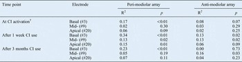
The ability of electrically evoked compound action potential thresholds to predict T-levels was analysed using linear regression (Figure 6b). While electrically evoked compound action potential thresholds at each time predicted audibility (i.e. electrically evoked compound action potential thresholds were higher than T-levels), most electrically evoked compound action potential thresholds for both arrays only explained less than 20 per cent of the variation in T-levels (Table I). Measures collected at week one were most predictive, with significant associations at basal (number 3) and mid- (number 9) electrodes for both arrays, and at an apical (number 20) electrode for the peri-modiolar array.
Relationship between electrically evoked compound action potential thresholds and behavioural thresholds (T-levels)*

* Assessed using linear regression. †Electrically evoked compound action potentials during surgery. CI = cochlear implant; # = electrode number
Audiometric outcomes
Post-implantation aided thresholds
Similar to pre-implantation unaided and aided thresholds, aided thresholds post-implantation (Figure 2, filled symbols) did not differ in terms of surgical approach for the anti-modiolar array (F (1, 15) = 1.6, p = 0.23), sex (F (1, 15) = 0.2, p = 0.64) or ear implanted with the anti-modiolar array (F (1, 15) = 0.1, p = 0.78), and were clinically acceptable.
Speech perception
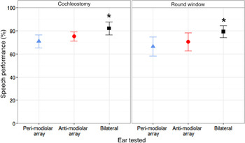
Speech perception significantly differed according to ear tested (F (2, 28) = 4.4, p = 0.02), but there was no difference between the two surgical approaches for the anti-modiolar array (F (2, 28) = 0.2, p = 0.82). In particular, while speech perception was similar between ears implanted with each array (p = 1.0), bilateral speech perception was significantly better than that of the ear implanted with the peri-modiolar array (p = 0.02). Similar trends were found but were not significant for the ear with the anti-modiolar array (p = 0.08).
Discussion
This study sought to determine whether a new anti-modiolar array delivers similar outcomes to a peri-modiolar array when implanted in the same child, and considered whether these outcomes are affected by surgical approach. Overall, the results indicated: (1) significant differences between the two arrays for both electrophysiological and behavioural measures, particularly in basal electrodes; (2) no differences in functional performance; and (3) no overall differences in outcomes for cochleostomy versus round window surgical approaches for inserting the anti-modiolar array.
Stimulation parameters for both arrays changed similarly and stabilised
Overall, electrophysiological and behavioural measures stabilised over a similar time course between the two arrays, which is important for delivering consistent sound to both ears in order to promote bilateral development. The pattern of increased impedance following surgery, and subsequent decrease and stabilisation after a month of electrical stimulation (Figure 3a, b), likely reflects growth then subsequent polarisation of surrounding fibrous tissue,Reference Swanson, Seligman and Carter 20 thereby decreasing resistance.Reference Tykocinski, Duan, Tabor and Cowan 21 While connective tissue still encapsulates the electrodes, electric stimulation can also detach some deposits which accumulated prior to device activation.Reference Charlet de Sauvage, Lima da Costa, Erre and Aran 22 This process seems to occur in the same way regardless of array type (Figure 3a, b) or manufacturer.Reference Saunders, Cohen, Aschendorff, Shapiro, Knight and Stecker 4 – Reference van Wermeskerken, van Olphen and Smoorenburg 6 , Reference Hughes, Vander Werff, Brown, Abbas, Kelsay and Teagle 23 – Reference Paasche, Bockel, Tasche, Lesinski-Schiedat and Lenarz 29
Similar to impedance, and in line with previous studies,Reference Gordin, Papsin, James and Gordon 2 , Reference Hughes, Vander Werff, Brown, Abbas, Kelsay and Teagle 23 , Reference Gordon, Papsin and Harrison 30 electrically evoked compound action potential thresholds decreased following cochlear implant activation and stabilised within a week (Figure 5b), again likely reflecting cochlear changes following implantation and subsequent electric stimulation.Reference Hughes, Vander Werff, Brown, Abbas, Kelsay and Teagle 23 , Reference Gordon, Papsin and Harrison 30 , Reference Gordin, Papsin and Gordon 31
Unlike impedance and electrically evoked compound action potential thresholds, behavioural thresholds to current (T-levels) remained relatively constant over the first three months of cochlear implant use (Figure 4a). This is also seen in other arrays,Reference Gordin, Papsin, James and Gordon 2 , Reference Saunders, Cohen, Aschendorff, Shapiro, Knight and Stecker 4 , Reference Hughes, Vander Werff, Brown, Abbas, Kelsay and Teagle 23 , Reference Gordon, Papsin and Harrison 30 and is not too surprising given that impedance and T-levels do not highly correlate.Reference van Wermeskerken, van Olphen and Smoorenburg 6 Individual variation can exist,Reference Hughes, Vander Werff, Brown, Abbas, Kelsay and Teagle 23 , Reference Gordon, Papsin and Harrison 30 , Reference Shapiro and Waltzman 32 but other factors may contribute more to variation in behavioural responses, such as array proximity to the modiolus,Reference Saunders, Cohen, Aschendorff, Shapiro, Knight and Stecker 4 or the child's awareness of stimulationReference Gordon, Papsin and Harrison 30 and reliability in responding to sound as they develop.Reference Gordin, Papsin, James and Gordon 2 , Reference Gordon, Papsin and Harrison 30 Similarly, as children acclimatise to electrical stimulation and become more tolerant to higher stimulation over time, comfort levels routinely increase (Figure 4a), regardless of array type or manufacturer.Reference Gordin, Papsin, James and Gordon 2 , Reference Hughes, Vander Werff, Brown, Abbas, Kelsay and Teagle 23 , Reference Gordon, Papsin and Harrison 30 , Reference Raghunandhan, Ravikumar, Kameswaran, Mandke and Ranjith 33
Stimulation parameters varied between array and electrode position
Although stimulation parameters stabilised similarly for each array, values significantly differed between the arrays at each time point. In general, basal electrodes exhibited the largest differences in impedance, compliance limit, behavioural responses to current (T-level and comfortable loudness (C-level)) and evoked responses (electrically evoked stapedial reflex thresholds and electrically evoked compound action potentials). This is not just a function of electrode size (e.g. Figure 3b),Reference Saunders, Cohen, Aschendorff, Shapiro, Knight and Stecker 4 , Reference Busby, Plant and Whitford 5 but may be dominated by modiolar proximity:Reference Gordin, Papsin, James and Gordon 2 , Reference Saunders, Cohen, Aschendorff, Shapiro, Knight and Stecker 4 , Reference Busby, Plant and Whitford 5 both arrays are close to the modiolus in the cochlear apex, but the anti-modiolar array sits further from the modiolus and closer to the lateral wall in the base.Reference Huang, Reitzen, Marrinan, Waltzman and Roland 34
Although present, array differences for these simultaneously implanted children were smaller than those for a different cohort of children implanted with two different arrays (older generation straight anti-modiolar array and the same pre-curved peri-modiolar array) in sequential surgical procedures (T-level, 12.8 ± 2.0 vs 32.3 ± 28.9 current units; C-level, 11.9 ± 2.1 vs 39.5 ± 23.8 current units; electrically evoked compound action potentials 6.6 ± 3.6 current units vs 22.7 ± 29.3 current units; electrically evoked stapedial reflex thresholds 8.7 ± 2.6 current units vs 19.9 ± 19.7 current units),Reference Gordon, Chaikof, Salloum, Goulding and Papsin 35 highlighting one of the benefits of simultaneous implantation.
Anti-modiolar array had lower impedance than peri-modiolar array
Measured impedance differences between the two arrays were subtle (overall: 0.2 ± 0.2 kΩ), but significant at extremes of the cochlea (Figure 3a). This translates into slightly higher compliance limits for the anti-modiolar array for basal electrodes, but lower limits at apical electrodes (Figure 3c). These apical and basal differences were also observed for older generation straight anti-modiolar and curved peri-modiolar arrays implanted in adults,Reference Saunders, Cohen, Aschendorff, Shapiro, Knight and Stecker 4 , Reference Busby, Plant and Whitford 5 and were mostly attributed to the larger electrodes of the anti-modiolar array rather than differential fibrous tissue growth. In contrast, normalised impedance was significantly lower for the thin anti-modiolar versus peri-modiolar array at all but apical electrodes, indicating less fibrous tissue growth and intra-cochlear trauma despite a larger surrounding volume of fluid.Reference van Wermeskerken, van Olphen and Smoorenburg 6 This suggests that the thin anti-modiolar array may indeed be less traumatic than the peri-modiolar array or previous generations of straight arrays. However, it is important to note that despite these impedance differences across arrays and electrodes, all average values were clinically acceptable (less than 15 kΩ).
Anti-modiolar array required greater current levels to evoke responses
Unlike impedances, behavioural responses (T- and C-levels) and electrophysiological responses (electrically evoked stapedial reflex thresholds and electrically evoked compound action potential thresholds) required higher current levels for the new anti-modiolar array. As with older generations of anti-modiolar and peri-modiolar arrays,Reference Gordin, Papsin, James and Gordon 2 , Reference Saunders, Cohen, Aschendorff, Shapiro, Knight and Stecker 4 , Reference MacDonald, Sohn, Papsin and Gordon 19 radial distance rather than electrode size likely contributed to these stimulation differences.Reference Saunders, Cohen, Aschendorff, Shapiro, Knight and Stecker 4
Although lower impedances generated greater compliance limits for the anti-modiolar array, C-levels differed to a greater extent, leaving less ‘headroom’ between average comfort levels and compliance limits for the anti-modiolar array (Figure 4c). This may have important implications for ease of programming, loudness growth, maintaining stimulation on each electrode, sound fidelity and battery consumption between arrays.
Also similar to older arrays,Reference Gordin, Papsin, James and Gordon 2 , Reference Gordon, Papsin and Harrison 30 , Reference Polak, Hodges, King and Balkany 36 – Reference Propst, Papsin, Stockley, Harrison and Gordon 38 higher current levels were required to elicit responses in the base of the cochlea through the anti-modiolar array versus the mid-cochlea through the peri-modiolar array. Perhaps stimulation requirements for the arrays differed along the cochlea because of differing patterns of fibrous tissue growth,Reference Saunders, Cohen, Aschendorff, Shapiro, Knight and Stecker 4 cell types,Reference Newbold, Richardson, Huang, Milojevic, Cowan and Shepherd 24 and neural survival or densityReference Shepherd, Hatsushika and Clark 3 , Reference Polak, Hodges, King and Balkany 36 , Reference Polak, Hodges and Balkany 37 , Reference Rattay, Leao and Felix 39 along the arrays, or differing insertion techniques and positioning in the cochlea. The peri-modiolar array sits closer to the modiolus in the base and apex, but sits further in the mid-cochlea,Reference Huang, Reitzen, Marrinan, Waltzman and Roland 34 , Reference Cohen, Saunders, Knight and Cowan 40 particularly after packing the cochleostomy.Reference Gordin, Papsin and Gordon 31 This once again supports the hypothesis that modiolar proximity is beneficial as it allows the auditory system to be stimulated with less current.
Surgical approach did not affect stimulation parameters
The round window approach has been proposed to be less traumatic to cochlear structuresReference Adunka, Gstoettner, Hambek, Unkelbach, Radeloff and Kiefer 11 , Reference Adunka, Unkelbach, Mack, Hambek, Gstoettner and Kiefer 12 , Reference Briggs, Tykocinski, Stidham and Roberson 14 and is therefore currently the principal surgical approach used for inserting anti-modiolar arrays. However, insertions via cochleostomy inferior to the round window rendered similar histological responses to round window insertions, indicating similar intra-cochlear trauma.Reference Briggs, Tykocinski, Xu, Risi, Svehla and Cowan 13
Consistent with histological reports, there was no difference in the degree and stability of impedance or compliance limit between groups of children who received the anti-modiolar array with a round window or cochleostomy approach, suggesting similar cochlear responses and trauma (Figure 3). Although slightly fewer children tended to have a high impedance fluctuation index for the anti-modiolar array with the round window (2 out of 21) versus cochleostomy (12 out of 40) approach, group mean indices were similar between approaches. Furthermore, surgical approach did not affect stimulation levels required to elicit behavioural (Figure 4) and electrophysiological responses (Figure 5). Therefore, it appears that the size of the new anti-modiolar array contributed more to reduced cochlear trauma than surgical approach, and modiolar proximity contributed more to stimulation level required to stimulate the auditory nerve.
Electrophysiological measures predicted audibility
Electrophysiological measures are often used in populations with unreliable or inconsistent behavioural responses, such as very young paediatric populations and patients who are difficult to test. For these populations, clinicians rely on objective electrophysiological responses to help set parameters while programming cochlear implants. Different measures can be used, but often electrically evoked compound action potentials are used to predict thresholds and electrically evoked stapedial reflex thresholds are used to predict comfortable loudness current levels.Reference Gordin, Papsin, James and Gordon 2 , Reference Gordon, Papsin and Harrison 30 , Reference Gordon, Chaikof, Salloum, Goulding and Papsin 35
As electrically evoked stapedial reflex thresholds were mostly obtained during surgery, the ability of electrically evoked stapedial reflex thresholds to predict C-levels for each array was not fully determined. In early programming (i.e. within three months), C-levels were set incrementally, relative to T-levels, to gradually increase dynamic range and tolerance for electrical stimulation.Reference Gordon, Papsin and Harrison 30 However, the differing levels required for both electrophysiological and behavioural thresholds suggest that a fixed dynamic range, even with early implant use, may not accurately reflect the loudness growth of electrodes that are responding differently to stimulation. As such, it may be important to predict or measure C-levels independently from T-levels.
As observed previously,Reference Gordon, Papsin and Harrison 30 correction factors between electrically evoked compound action potential and behavioural thresholds (Figure 6a) differed by time and electrode, but not array. Importantly, 25 to 31 current unit larger correction factors were required when using electrically evoked compound action potential thresholds obtained during surgery to predict T-levels at device activation than when using both electrically evoked compound action potential thresholds and T-levels measured in the same appointment. Although no further adjustments were required to account for the type of array, further adjustments for a mid- or basal electrode may be warranted.
Although useful when no behavioural response can be obtained, correction factors are not ideal. Most electrically evoked compound action potential thresholds for both arrays only explained less than 20 per cent of the variation in T-levels (Table I), which is consistent with previously reported relationships between electrically evoked compound action potential thresholds and T-levels in children and adults.Reference Gordon, Papsin and Harrison 30 , Reference Raghunandhan, Ravikumar, Kameswaran, Mandke and Ranjith 33 , Reference Franck 41 – Reference Holstad, Sonneveldt, Fears, Davidson, Aaron and Richter 45 Therefore, using T-levels set based on electrically evoked compound action potential thresholds may result in a loudness imbalance overall and across the arrays.Reference Holstad, Sonneveldt, Fears, Davidson, Aaron and Richter 45 However, approximate inter-implant level differences at suprathreshold levels required to perceive a balanced bilateral input for a pair of electrodes may be predicted by electrically evoked compound action potential thresholds measured for each array,Reference Gordon, Chaikof, Salloum, Goulding and Papsin 35 although this was beyond the scope of this study and would need to be confirmed with these two arrays. Because electrically evoked compound action potential thresholds were mostly predictive of audibility (Figure 6b), C-levels could be set above electrically evoked compound action potential thresholds, as long as the child is comfortable with the inputs at early stages of device use. Differences in stimulation levels between the two arrays may be required.
Thus, electrophysiological measures indicated differences in required stimulation levels between the two arrays, and predicted audibility in both the peri-modiolar and anti-modiolar arrays, but would be best used in a battery with behavioural measures to program cochlear implants in children.
Audiometric outcomes were similar for each array
Although parameter differences existed between arrays, audiometric outcomes were not significantly affected: aided access to sound (Figure 2, filled symbols) and speech perception (Figure 7) were similar between ears implanted with the two different arrays. Doshi et al. also found no significant differences between the new thin, straight anti-modiolar array and standard pre-curved peri-modiolar array in adults.Reference Doshi, Johnson, Mawman, Green, Bruce and Freeman 15 They proposed that reduced trauma from the narrow flexible design and round window approach may have contributed to the better performance exhibited with the new versus older anti-modiolar arrays. However, surgical approach did not affect speech perception in the present study (Figure 7), or in a study comparing adults who received the new thin anti-modiolar array via cochleostomy or a round window approach.Reference Hassepass, Aschendorff, Bulla, Arndt, Maier and Laszig 17 Similar speech performance has also been documented in adults implanted with older anti-modiolar and peri-modiolar arrays,Reference Fitzgerald, Shapiro, McDonald, Neuburger, Ashburn-Reed and Immerman 46 although other studies identified better word and sentence perception in quiet and noisy conditions with the same peri-modiolar array compared to older peri-modiolar and anti-modiolar arrays in both children and adults.Reference Gordin, Papsin, James and Gordon 2 , Reference Bacciu, Pasanisi, Vincenti, Guida, Barbot and Berghenti 7
Speech perception in quiet conditions for the ear with the peri-modiolar array (blue triangle) and anti-modiolar array (red triangle), and for both ears together (bilateral; black square), in children who received the anti-modiolar array via cochleostomy or round window approach.

-
• Differences in stimulation parameters and audiometric outcomes have been reported for anti- versus peri-modiolar cochlear implant electrode arrays
-
• A new slim anti-modiolar array has been developed to reduce cochlear trauma during implantation
-
• This study compared outcomes and stimulation parameters between this anti-modiolar array and the peri-modiolar array in the same children
-
• Significant differences existed in stimulation levels and parameters between the two arrays that persisted four months following surgery
-
• Surgical approach to insert the new array did not affect level or stability of stimulation parameters
While similar speech perception may indicate comparable access to, and development of, speech with the two different arrays, it is also possible that ceiling effects occurred in quiet conditions. To truly identify whether the children developed similarly with stimulation through the two different arrays, they could be tested using more difficult noise conditions (i.e. babble, steady-state noise and different signal-to-noise ratios) and different tasks. This warrants consideration given the importance of consistent and balanced bilateral input to the developing auditory system.Reference Gordon, Deighton, Abbasalipour and Papsin 47 – Reference Gordon, Valero and Papsin 49 Further investigation of binaural hearing abilities and bilateral development in the auditory system is needed to ensure equivalency of function and developmental symmetry, as well as the ability to use the sound delivered by ears implanted with two different arrays at the same time.
Conclusion
Significant but clinically acceptable differences in stimulation parameters between peri-modiolar and anti-modiolar electrode arrays persisted for four months after surgery in children using bilateral cochlear implants. Parameter levels were within an expected range for each array,Reference Gordon, Papsin and Harrison 30 and the differences between the two devices were smaller than previously reported in children who received two different devices sequentially, highlighting the benefit of simultaneous implantation. However, device asymmetries should still be considered, and methods to optimise stimulation parameters in bilateral cochlear implant users might account for such differences. Electrically evoked compound action potential thresholds are best used to predict audibility, as individual prediction of thresholds (T-levels) at specific electrodes at specific times is low. The surgical approach used to implant the anti-modiolar array did not have an effect on level or stability of stimulation parameters.
Acknowledgements
The authors thank all the children who participated in this study and their families for their support. The authors would also like to thank the Cochlear Implant Program audiologists (Patricia Di Santo, Susan Druker, Mary Lynn Feness, Gina Goulding, Laurie MacDonald, Rebecca Malcolmson and Valerie Simard) for assistance with the measurements. A special thanks to Alexander Papaioannou and Vikram Rao, volunteers who helped with data collection.
Appendix 1. Further details regarding array differences affecting cochlear implant programming
Open electrodes
Both arrays had a similar number of open electrodes (chi-square (1) = 0.77, p = 0.38): five children (7.8 per cent) had one open electrode on the anti-modiolar array (electrodes 3, 12, 13, 15 and 16) and three children (4.7 per cent) had one open electrode on the peri-modiolar array (electrodes 4, 7 and 11). All but two of the open electrodes were detected at the intra-operative time point, and two additional open electrodes were noted at device activation. Shorted electrodes did not occur in any children.
Impedance fluctuation
Variation in impedance was further quantified using two measures. Firstly, fluctuation in impedance across each array (standard deviation across electrodes) significantly decreased over time (F (2.4, 84.8) = 14.1, p < 0.001), and this decrease occurred gradually for the cochleostomy group versus abruptly after activation for the round window group (F (2.4, 84.8) = 4.3, p = 0.012). There was no significant difference between arrays (F (1, 35) = 0.4, p = 0.53). Secondly, the fluctuation index measures variation (standard deviation) in impedance over time (week one to month three post-activation), averaged for each electrode, and is considered high if exceeding 1.5. Of the 61 children for which this index could be measured, 38 (62 per cent) had normal indices, and equal numbers of children had abnormally high fluctuation with the anti-modiolar arrays (14 out of 61, 23 per cent) and peri-modiolar arrays (9 out of 61, 15 per cent) (chi-square (1) = 1.8, p = 0.18). More children had significant fluctuation after the cochleostomy (12 out of 40, 30 per cent) versus round window approach (2 out of 21, 9.5 per cent) for the anti-modiolar array (chi-square (1) = 10.6, p = 0.001). The manufacturer recommends a higher criterion for the anti-modiolar array (1.8); under this criterion, 6 out of 14 children (43 per cent) with previously abnormal anti-modiolar array fluctuation indices are considered to be within normal limits. Overall, there was no difference in mean fluctuation index between arrays (F (1, 59) = 0.7, p = 0.39) or approach for the anti-modiolar array (F (1, 59) = 3.0, p = 0.09).
Correction factors differ by electrode and time
The difference between electrically evoked compound action potential and behavioural (T-level) thresholds was greater at a mid-electrode (number 9) than an apical electrode (number 20) (p = 0.046). Regardless of electrode, the difference between electrically evoked compound action potential thresholds and T-level was greater when using the electrically evoked compound action potential thresholds measured during surgery to estimate behavioural thresholds at cochlear implant activation (60.3 ± 3.4 current units) versus using electrically evoked compound action potentials and T-levels measured at week one (28.8 ± 5.2 current units, p < 0.001) and month three (35.0 ± 4.6 current units, p < 0.001) post-activation, which were similar to each other (p = 0.39).