Introduction
Ultra-wideband antenna system has low power consumption, high speed and good anti-interference performance, which has attracted the attention of many scholars [Reference Kang, Li, Wang and Shi1]. MIMO antenna technology has its unique advantages in improving data transmission rate and channel capacity [Reference Roshna, Deepak, Sajitha, Vasudevan and Mohanan2]. Considering the advantages of the UWB and MIMO technology and combining them, the rate of wireless communication is further improved. However, ensuring that the antenna system is placed in portable facilities with limited space and maintaining high isolation of the antenna system is a challenge. For the purpose of reducing the coupling between MIMO antenna ports, many technical methods have been seen in many literature reports [Reference Luo, Hong and Zhong3–Reference Wang, Du, Yang, Ma, Zhao, Cui and Xi14], such as defected ground structure (DGS) [Reference Luo, Hong and Zhong3–Reference Li, Chu, Li and Xia5], the use of wideband neutralization line [Reference Zhang and Pedersen6, Reference Diallo, Luxey, Le Thuc, Staraj and Kossiavas7], polarization diversity [Reference Sipal, Abegaonkar and Koul8–Reference Tripathi, Mohan and Yadav10], electromagnetic band-gap (EBG) structure or metamaterial [Reference Li, Feresidis, Mavridou and Hall11] and parasitic decoupling structures [Reference Zhang, Ying, Xiong and He12–Reference Wang, Du, Yang, Ma, Zhao, Cui and Xi14].
Documents [Reference Luo, Hong and Zhong3–Reference Li, Chu, Li and Xia5] proposed to etch T-shaped grooves and rectangular grooves on the ground. This structure, called defective ground, is often used to enhance the isolation between antenna ports. The decoupling principle is that the current path is extended and the surface current is suppressed. A wideband neutralization line is introduced in [Reference Zhang and Pedersen6, Reference Diallo, Luxey, Le Thuc, Staraj and Kossiavas7], this technology connects two antenna elements with a neutralization line. By introducing a new coupling path, the coupling current is canceled so that the isolation between antenna ports is improved. Polarization diversity technology enhances the isolation between antenna ports by placing antenna elements orthogonally [Reference Sipal, Abegaonkar and Koul8–Reference Tripathi, Mohan and Yadav10]. EBG structure is also often used to enhance the isolation between antenna ports. Literature [Reference Li, Feresidis, Mavridou and Hall11] proposes a double-layer EBG structure to decrease coupling, which has isolation >28 dB. Although this periodic structure metamaterial has an ideal decoupling effect, its limited bandwidth is not suitable for ultra-wideband systems. Parasitic decoupling structure loaded on the common ground is introduced to achieve the effect of high isolation [Reference Zhang, Ying, Xiong and He12–Reference Wang, Du, Yang, Ma, Zhao, Cui and Xi14]. A tree-like decoupling structure achieves isolation better than 16 dB [Reference Zhang, Ying, Xiong and He12]. In [Reference Najam, Duroc and Tedjni13], a modified inverted Y-shape decoupling stub is put forward to improve the isolation (better than 20 dB). Besides, a decoupling structure composed of many strips is used in the middle of the ground to form a band-reject filter, thereby achieving good port isolation [Reference Wang, Du, Yang, Ma, Zhao, Cui and Xi14].
This paper proposes a new parasitic decoupling design for compact UWB-MIMO antenna. The parasitic decoupling structure is made up of a pair of closed square rings and a T-shape stub. By introducing a new coupling path, the surface coupling current on the common ground between antennas is canceled out, which significantly reduces the coupling between the antennas. Through this structure, the antenna has a high isolation greater than 25 dB over the whole design frequency band (3.3–12 GHz).
Design principle of an antenna and parasitic decoupling structure
Geometric structure of the antenna
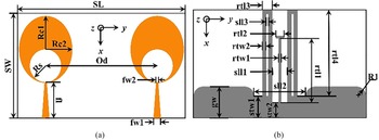
The geometric structure of the designed antenna is given in Fig. 1, it includes a common ground loaded with a parasitic decoupling structure and two identical elliptical monopoles fed by a tapered microstrip. A FR4 dielectric board is used as a substrate for antenna etching (thickness hs = 1.6 mm, relative permittivity εr = 4.4), which has the overall size of 25 × 40 mm2. Two identical radiation elements are placed symmetrically on the upper layer of the dielectric board with a center-to-center distance of 26.6 mm, and the common ground plane loaded with the parasitic decoupling stub is placed on the lower layer of the dielectric board. The elliptical monopole intersects the end of the tapered microstrip by 0.2 mm. A circular slot is etched on the elliptical monopole, and it is tangent to the end of the tapered microstrip. The parasitic decoupling structure consists of a pair of closed square rings and a T-shape stub etched in a rectangular slot.
Configuration of the proposed antenna (a) top view and (b) bottom view.

UWB antenna element
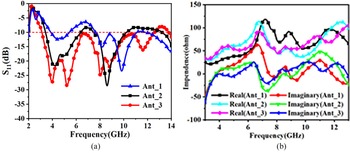
Figure 2 gives several shapes of the final antenna design during its evolution, which the Ground_3 is considered as the common ground for simulation. And the introduction of Ground_3 is illustrated in Fig. 4. The final antenna element (Ant_3) is obtained by using tapered microstrip and etching a circular slot on the elliptical monopole for the initial antenna (Ant_1), while keeping the same dimensions for the ellipse part. Figure 3(a) shows the simulated S-parameter changes of these two improvement measures. It can be known from Fig. 3(a) that the Ant_3 has a better impendence matching performance in the desired frequency band (3.3–12 GHz).
Different structures of antenna elements used in the evolution of the final antenna.

(a) Simulated S11 of the different antenna elements. (b) Simulated input impendence of three antenna units against frequency.

In order to facilitate the comparison with the input impedance of Ant_1, put the input impedance of these three antennas in a graph, so that you can better see the effect of the two improvement measures on the antenna input impedance Impact.
Compared with the Ant_1, the changes of the real and imaginary input impedances of the Ant_2 and the Ant_3 over the entire operating frequency band can be seen from Fig. 3(b). It can be seen by comparison that the real part of the input impedance of the Ant_3 over the entire operating frequency band tends to 50 Ω, while the imaginary part of the input impedance tends to zero. Therefore, the improvement of impedance matching characteristics in the low-frequency band can be attributed to these two improvement measures.
Effect of parasitic decoupling structure
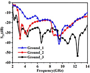
By adding different structures on the common ground, the final antenna obtains good isolation over the designed frequency band. Figure 4 shows the common ground without any decoupling structure (Ground_1) and the common ground with different decoupling structures (Ground_2 and Ground_3), which the Ant_3 is used to study the effect of different grounds. The simulated S-parameters with the different ground planes are given in Fig. 5, from which we can observe that the T-shape stub improves the isolation property of the antenna in certain frequency bands and the closed square ring decreases the coupling effect against the most operating band. The comparison shows that by loading a pair of closed square rings on the common ground, the isolation between the antenna ports can be significantly improved.
Different geometries of a common ground plane.

Simulated S21 to illustrate the decoupling effect of change in the ground plane.

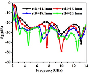
In order to explore the influence of the closed square rings on the isolation of the designed antenna, a simulation study was made on the different lengths of the closed square rings. As shown in Fig. 6, when rtl4 changes from 14.1 to 20.1 mm, the current on the parasitic structure appears multi-mode resonance in the working frequency band, which cancels out the coupling current on the common ground. Therefore, the parasitic stub has the effect of broadband decoupling, and the decoupling effect between antenna ports is also improved.
Influence of different rtl4 on S21.

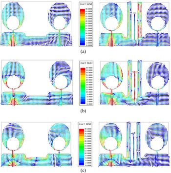
The broadband parasitic branch designed in this paper is essentially a resonator, which can resonate at different frequencies. Figure 7 gives the current distribution on the antenna surface and common ground with or without decoupling structure. By observing the surface current distribution on the common ground loaded with parasitic decoupling branches, as shown in Fig. 7, it can be seen that there is a current with the opposite phase on this branch. Compared with the antenna without any decoupling branches, the coupling current on the second antenna is significantly weakened.
Surface current distributions of the UWB-MIMO antenna without/with decoupling structure at (a) 4.5 GHz, (b) 8 GHz and (c) 10.5 GHz.

The designed UWB-MIMO antenna is optimized by the commercial simulation software HFSS, and the parameters optimized for the antenna were eventually determined with SL = 40 mm, SW = 25 mm, fl = 8.7 mm, fw1 = 1.8 mm, fw2 = 0.5 mm, Rc1 = 8 mm, Rc2 = 6.4 mm, R1 = 2 mm, Rs = 3.9 mm, gw = 7.1 mm, sll1 = 3.4 mm, sll2 = 1.2 mm, stw1 = 4.9 mm, stw2 = 3.3 mm, sll3 = 0.4 mm, rtl1 = 15.2 mm, rtw1 = 0.5 mm, rtl2 = 1.7 mm, rtw2 = 1 mm, rtl3 = 2.4 mm, rtl4 = 20.1 mm, Od = 26.6 mm.
Test results and analysis
Impendence matching and isolation performance
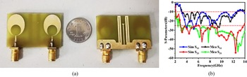
Considering the actual operating characteristic of the designed antenna, it was manufactured and the final antenna was tested with a vector network analyzer (Anritsu MS46322A). Figure 8(a) demonstrates the physical diagram of the manufactured antenna and Fig. 8(b) gives the schematic diagram of S-parameters of the antenna simulation and measurement results. According to Fig. 8(b), we can conclude that the antenna measurement results are basically in accordance with the simulation results. Through the test, the operating frequency range of the final antenna is 3.3–12 GHz, and the antenna obtains better than 25 dB isolation over the whole operating band.
(a) Photograph of the fabricated antenna. (b) Simulated and measured S-parameter of the proposed antenna.

Radiation characteristic
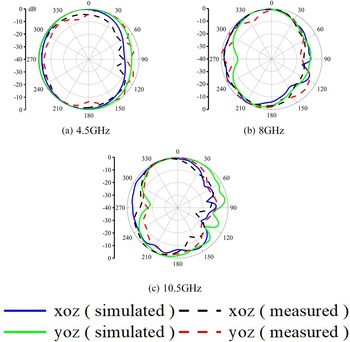
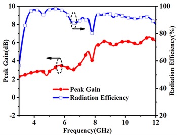
The radiation situation of the designed antenna in free space can be reflected by the antenna radiation pattern. Figure 9 shows the two-dimensional (2D) patterns of the designed antenna in different planes (xoz and yoz planes) at three frequencies (4.5, 8 and 10.5 GHz). By the far-field test system in Anechoic Chamber, the radiation properties of the fabricated antenna are measured and the actual measurement results are acquired by exciting one port and terminating a 50 Ω matched load on the other port. The proposed antenna exhibits quasi-omnidirectional characteristic at 4.5 and 8 GHz, while at 10.5 GHz, the antenna pattern deteriorates. Analyzing the surface current vector of the antenna at high frequency, it can be seen that the current on the antenna radiation surface has a lateral current, as shown in Fig. 7(c), so the pattern will be distorted. The actual antenna peak gain and radiation efficiency variation curves over the whole designed frequency band are given in Fig. 10, from which we can observe that the antenna peak gain is 2.5–6.6 dBi and the radiation efficiency is better than 80%. In addition, the increase of gain with frequency is due to the partial ground structure of the antenna, so the induced current generated on the T-shaped parasitic branch on the common ground contributes to the gain. It can be seen that the performance of the antenna is relatively good in the operating frequency band, which meets the requirements of the ultra-wideband antenna.
Radiation pattern in X–Z and Y–Z plane at 4.5, 8 and 10.5 GHz.

Measured peak gain and radiation efficiency of the antenna.

Diversity performance
Diversity performance is also a technical indicator that MIMO antennas need to consider. The diversity performance could be described by the envelope correlation coefficient (ECC). Using the measured S-parameters, ECC(ρeij) could be evaluated by the following expression (1) [Reference Khan, Capobianco, Najam, Shoaib, Autizi and Shafique15].

where i and j are the numbers of ports, XPR is the cross-polarization ratio, and Pθ and Pφ are the θ and φ components of the angular density functions of the incoming wave, respectively. Ω is the solid angle of the spherical coordinate.
The ECC simulation result of the antenna is displayed in Fig. 11. The value of ECC is quite low (less than 0.01) over the whole designed frequency band (3.3–12 GHz), as presented in Fig. 11, which shows the antenna not only has a good correlation coefficient but also a good diversity gain.
Simulated ECC of the proposed antenna.

To further give prominence to the innovation of this design, the comparison between the antenna proposed in this paper and some antennas mentioned in recent literature is listed in Table 1. Through contrast, it is found that the antenna is not only compact and has high port isolation, which makes it suitable for modern portable devices.
Comparisons with previously reported antennas.

Conclusion
This Letter introduces a new parasitic decoupling design suitable for UWB-MIMO antenna. The designed antenna has outstanding working performance, and the measured results prove that by using the proposed closed square ring and T-like stub, the designed antenna has excellent isolation (S21 < −25 dB) in the operating band (3.3–12 GHz). In addition, the antenna peak gain is relatively good, the radiation efficiency is higher, and the lower ECC indicates that the antenna has advantages in diversity performance.
Acknowledgements
This work is supported by the Key Research and Development Program in Shaanxi Province of China (No. 2020GY-016).
 Huiqing Zhai was born in Daan, Jilin Province, China. He received the Ph.D. degree in electromagnetic fields and microwave technology from Xidian University, Xi'an, China, in 2004. From 2005 to 2008, he was a JSPS research fellow with Tohoku University, Sendai, Japan. From 2008 to 2010, he was a Research Fellow with the University of Texas at Arlington, Arlington, TX, USA. Since 2019, he has been the Director of the Microwave Telecommunication Engineering Department, Xidian University, where he is currently a full professor and Ph.D. supervisor. He has authorized or co-authored over 100 papers in the referred journal, and over ten authorized invention patents. His current research interests include antennas for wireless communication, electromagnetic materials, electromagnetic detection, and electromagnetic invisibility cloaking.
 Kunming Zhang was born in Zhumadian, China. He received the B.S. degree in electronic information science and technology from Luoyang Normal University in 2017. He is currently pursuing the M.S. degree at the State Key Laboratory of Antenna and Microwave Technology, School of Electronic Engineering, Xidian University. His current research interests include the design and analysis of ultra-wideband antennas, millimeter wave antennas and MIMO antennas.
 Yu Huo was born in Hengshui, China. He received the B.S. degree in electronic information science and technology from Xidian University in 2018. He is currently pursuing the M.S. degree at the State Key Laboratory of Antenna and Microwave Technology, School of Electronic Engineering, Xidian University. His current research interests include the design and analysis of base station antennas, millimeter wave antennas and MIMO antennas.
 Chaozong Guo was born in Hebei, China, in 1997. He received the bachelor's degree in electronic and information engineering from Xidian University, Xi'an, China, in 2017, where he is currently pursuing the Ph.D. degree in an electromagnetic field and microwave technology. His current research interests include the decoupling of MIMO antennas, electromagnetic metamaterials.