I. INTRODUCTION
Low-standing wave ratio over a frequency band takes part very significant role in the design of microwave components [Reference Giger1, Reference Chana and Turner2]. In general, the impedance bandwidth of microstrip antenna is decreased with the area size reduction (for compact operation) of the patch. Therefore, bandwidth enhancement is one of the major considerations for the design of practical compact microstrip antennas [Reference Wong3]. However, efficiency of the antenna is reduced as the impedance bandwidth is increased. This problem with microstrip antennas can be overcome to some extent by enhancing the internal matching of the antenna [Reference Pozar4]. Low voltage standing wave ratio (VSWR) microwave component, in which the standing wave ratio is very close to 1, provides very good internal matching. Therefore, low VSWR is a useful method for the design of compact and wide band (bandwidth > 10%) microstrip antennas especially for single-layer probe-fed microstrip antennas.
A compact and broadband single-layer probe-fed microstrip antenna is presented in [Reference Deshmukh and Ray5]. Bandwidth of the antenna is increased by 28% when two quarter wavelength rectangular slots are inserted inside the patch of the antenna. However, the compactness of the antenna was 55%. In [Reference Chakraborty, Chowdhury and Bhatacharjee6–Reference Li, Xiong, Yu and He8], the size of single-layer coaxial-fed microstrip antennas has been reduced by 80–90%. However, the fractional bandwidths were <8% in all of the designs. A compact and broadband microstrip antenna is proposed in [Reference Prabhakar, Kummuri, Yadahalli and Munnappa9] using meandering slots in the ground plane. The compactness of the design was 83% when the bandwidth was about 38.3%. However, the design uses a microstrip line fed, which is feed method to achieve wide band operation of microstrip antennas.
In this paper, a compact single-layer coaxial probe fed wide band microstrip antenna has been proposed. The antenna can operate in WiMAX frequency range (3.36–3.715 GHz) with more than 10% wide operating bandwidth (≤VSWR 2). The internal matching of the antenna is very good as the VSWR = 1.0374 is achieved near the center frequency (3.5 GHz) of the operating band. The peak realized antenna gain is obtained about 2.15 dBi at 3.5 GHz. The proposed configuration was first optimized using the IE3D software followed by experimental verification.
II. ANTENNA CONFIGURATION
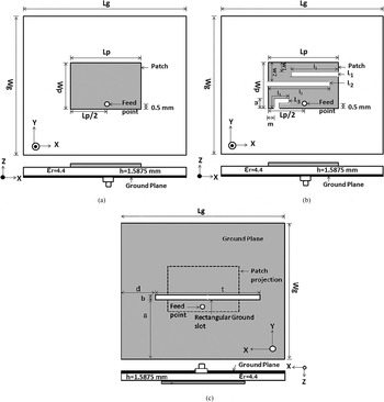
The geometry of the reference antenna (RA) is shown in Fig. 1(a). Dimensions of the RA parameters are: Lp = 12 mm, Wp = 8 mm, Lg = 36 mm, and Wg = 24 mm. The antenna is fed by a coaxial probe of inner diameter 0.6 at 0.5 mm away from the lower edge of the patch (as shown in Fig. 1).
Geometry of the microstrip antennas. (a) Conventional or RA, (b) proposed antenna front view (PA), (c) PA with rectangular ground slot (back view). Antenna dimensions are: L p = 12 mm, W p = 8 mm, L g = 36 mm, W g = 24 mm, and h = 1.5875. Optimized length of open-ended slots l 1 = 8.5 mm, l 2 = 11 mm, and l 3 = 5.1 mm. Optimized dimensions of the ground slot are: t = 22.95 mm, a = 9.9 mm, b = 0.8 mm, and d = 5.05 mm (d is fixed when t is varied for optimization).

Later, the geometry of the proposed antenna (PA) is formed by the insertion of three rectangular open-ended slots inside the patch and one rectangular slot inside the ground plane of the RA (as shown in Figs 1(b) and 1(c)). Optimized dimensions and positions of three open-ended slots (L 1, L 2, and L 3) are taken as: l 1 = 8.5 mm, l 2 = 11 mm, l 3 = 3.5 mm w 1 = 1.4 mm, w 2 = 2.7 mm, m = 1.1 mm, and n = 2.2 mm (Fig. 1(b)). Widths of all open-ended slots are 0.8 mm. Optimized dimensions of the ground slot are taken as: t = 23 mm, a = 9.9 mm, b = 1.5 mm, and d = 5 mm as shown in Fig. 1(c). These antennas are constructed with low-profile, low-cost, and easily available FR4 substrates (height = 1.5875 mm, ε r = 4.4, and tan δ = 0.02).
III. SIMULATED AND MEASURED RESULTS
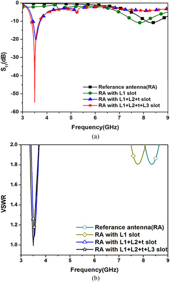
The PA is designed in four stages of modifications. Simulated S 11 (dB) versus frequency plot for each modification stage is shown in Fig. 2(a). At the first stage a rectangular microstrip antenna is designed to consider as RA (Fig. 1(a)). It is found that the −10 dB impedance bandwidth of the RA is 585 MHz (8.04–8.625 GHz). In the second stage, one rectangular open-ended slot L 1 is inserted inside the patch of the RA (Fig. 2(a)) for which the impedance bandwidth of 425 MHz is obtained at 7.8 GHz. In the third stage, one rectangular slots L 2 is inserted inside the patch and another slot t is inserted inside the ground plane (Figs 1(b) and 1(c)). Thus, the −10 dB impedance bandwidth of the antenna is increased to 8.6% about the center frequency of the band (3.4–3.728 GHz) for t = 22.95 mm. Later one inverted L-shaped slot (consists of two rectangular slots) L 3 is inserted inside the patch (Fig. 1(b)), which reduces the VSWR and enhance the matching of the structure. This antenna structure is considered as the proposed antenna. It is found from Fig. 2(a) that the PA resonant frequencies obtained at 3.5 GHz and −10 dB impedance bandwidth are 355 MHz (3.36–3.715 GHz), which is >10% around its center frequency.
(a) Simulated S 11 (dB) characteristics for each modification stage of the proposed antenna. (b) Simulated VSWR versus frequency plot of RA and PA.

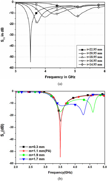
Simulated VSWR versus frequency plots of RA and PA are shown in Fig. 2(b). It is found that the VSWR 2 bandwidth of the RA is 585 MHz (8.04–8.625 GHz) or about 7.02% and lowest value of VSWR = 1.7955 is obtained at 8.32 GHz. Simulated VSWR 2 bandwidth of the PA is 355 MHz (3.36–3.715 GHz) or about 10.03%. Parametric studies on t and m have been investigated. Parametric variation of the ground slot length “t” of the PA is carried out and shown in Fig. 3(a). Lowest value of VSWR = 1.0037 is obtained at 3.5 GHz (near the center frequency of the VSWR 2 bandwidth) for t = 22.95 mm. Simulated S 11 (dB) characteristics for different values of parameter m is shown in Fig. 3(b). Different values of m are taken as 0.3 mm, 1.1 mm (PA), 1.9 mm, 2.7 mm; corresponding impedance bandwidths are 309.33 MHz (3.38–3.69 GHz), 355 MHz (3.36–3.715 GHz), 3.93.3 MHz (3.35–3.77 GHz), 185.26 MHz (4.48–4.67 GHz), and 988.4 MHz (3.4–4.39 GHz), respectively. The current distribution for the different modification stage of the antenna is given in Figs 4(a)–4(d). In Fig. 4(a), the current distribution of the RA is shown. When the slot L1 is inserted inside the patch surface, the current path is increased (Fig. 4(b)); thus the resonant frequency of the antenna is reduced to lower value (Fig. 2). The ground plane acts as a signal returning path. Therefore as the ground slot creates the discontinuity in the signal returning path the effective length of the current path is increased (Fig. 4(c)) and thus the resonant frequency is shifted further to lower value (Fig. 2). The slot L 3 reduces the effect of the standing wave in the structure (as shown in Fig. 4(d)); thus the matching is enhanced and the VSWR of the structure becomes very close to one Fig. 2(b).
(a) Parametric variation of the ground slot length of the PA. (b) Simulated S 11 (dB) characteristics for different values of parameter m.

(a–d) Current distribution at resonant frequency of each modification stages of the patch.

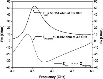
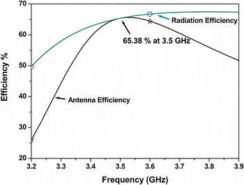
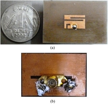
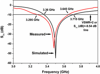
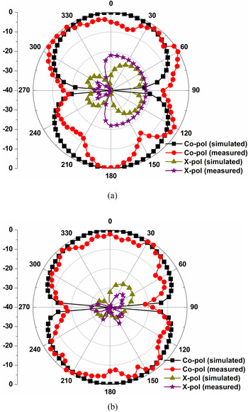
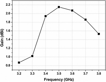
The resonance curve of the PA is illustrated in Fig. 5. It is obtained that the real value of impedance is nearly equal to 50 Ω (50.154 Ω) and the imaginary value is nearly equal to 0 Ω (−0.102 Ω) at 3.5 GHz. Efficiencies of the PA (antenna and radiation efficiencies) are found about 65% at 3.5 GHz (shown in Fig. 6). In this experiment, FR4 is used as a substrate, which is a low-cost and lossy material (loss tangent tan δ = 0.02). As the bandwidth and thickness (h) is a function of tan δ, therefore increase in loss tangent results in decrease the impedance variation and increase the loss in the patch. As an effect the bandwidth of the antenna is enhanced but efficiency is decreased. Thus, the microstrip antenna provides lower efficiency and gain to obtain its wider bandwidth [Reference Deshmukh and Ray5]. Prototype of the PA is shown in Fig. 7. Reflection co-efficient of the prototype is measured using Vector Network Analyzer Agilent N5 230A. Simulated and measured S 11 (dB) characteristics of the PA are compared in Fig. 8. Measured VSWR 2 bandwidth is obtained about 10.08% (3.295–3.645 GHz). Figures 9(a) and 9(b) show the normalized radiation patterns of the PA at 3.5 GHz. Resolution of the measurement is 10°. It is found that the antenna patterns are broadside with good isolation between co-polar and x-polar patterns for both y–z and x–z planes at 3.5 GHz. Good agreements between the measured and simulated power patterns are obtained. Gain of the antenna is measured with respect to a standard horn antenna. The maximum gain of the antenna of 2.15 dBi is obtained at 3.5 GHz as shown in Fig. 10. The work presents a compact (miniaturization ≥ 80%) and wide band (bandwidth ≥ 10%) microstrip antenna. Wide band can be easily obtained using a thick substrate or a microstrip line feed technique. However, the PA is designed with a single-layer thin substrate and excited with a co-axial probe feed. Furthermore, impedance bandwidth and gain of microstrip antenna are gradually reduced with the size miniaturization. In this work, the maximum gain of the antenna is >2 dBi.
Resonance characteristics of the PA.

Simulated efficiency versus frequency plot of the PA.

Designed prototype of the PA. (a) Front-view and (b) back-view.

Simulated and measured S 11 (dB) characteristics of the PA.

Normalized radiation pattern (a) y–z plane (b) x–z plane.

Measured antenna gain as a function of frequency of the PA.

IV. CONCLUSION
The design of a single-layer coaxial-fed compact microstrip antenna with wide band characteristic is presented in this paper. The PA offers a wide bandwidth of about 10% (simulated: 3.36–3.715 GHz and measured: 3.295–3.645 GHz) with compactness of 81.6%. Very low value of VSWR (1.00374) near the center frequency of the operating band (3.5 GHz) results in good radiation efficiency (about 65.38%) and peak gain (about 2.15 dBi) of the proposed structure with this compactness and wide bandwidth. Good agreements between simulation and measurement results were obtained.
ACKNOWLEDGEMENTS
We acknowledge gratefully the help provided by IIEST, Shibpur (formerly BESU), India and Dr. B. C. Roy Engineering College, Durgapur, India for measurement facilities.
 Aparna Kundu received Graduate degree in Electronic & Communications Engineering in 2006 from the Institutions of Engineers (India) and M. Tech. from West Bengal University of Technology in 2009. She is pursuing Ph.D. in the Department of Electronics and Communication Engineering at the National Institute of Technology, Durgapur. India. Her research interest is in compact microstrip antennas and wireless communication.
 Ujjal Chakraborty completed M. Tech. degree from the University of Burdwan in Microwave Engineering. He completed his Ph.D. work from the National Institute of Technology, Durgapur in 2014. His research area is in compact and frequency tunable microstrip antennas. Presently he is an Assistant Professor in Electronics and Communication Engineering Department in the National Institute of Technology, Silchar, Assam, India. He has published over 15 articles in National and International journals.
 Anup Kumar Bhattacharjee received his Bachelor of Engineering degree in Electronics and Telecom communication Engineering. He received his M.E. and Ph.D. from Jadavpur University, Kolkata in 1985 and 1989, respectively. Presently he is a Professor with the National Institute of Technology, Durgapur, West Bengal, India in Electronics and Communication Engineering Department. His area of research is in Microstrip Antenna, Embedded System, and Mobile Communications, etc. He has published over 120 articles in National and International journals.