I. INTRODUCTION
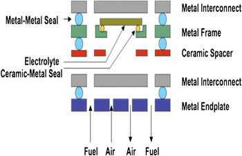
Solid oxide fuel cell (SOFC) is a solid-state energy conversion device that produces electricity by electrochemically combining fuel and oxidant across an ionic conducting oxide membrane at high temperatures.Reference Minh1 The planar SOFC configuration is superior to other configurations in terms of efficiency and power density but requires hermetic seals to prevent fuel–oxidant mixing and to provide electrical insulation to stacks.Reference Tu and Stimming2, Reference Yang, Xia, Meinhardt, Weil and Stevenson3 Seals required for a planar SOFC can be classified as metal–metal, ceramic–ceramic, and metal–ceramic seals (Fig. 1). Among these seals, metal–ceramic seals are particularly challenging because of their severe functional requirements as well as difficulty in selection of materials with conflicting requirements and associated processing. Glasses are most widely used to make metal–ceramic seals because these can be modified to have very close match of thermal expansion with other fuel cell components, and glass seals show good hermeticity along with good thermal and environmental stability.Reference Sohn, Choi, Kim, Song and Kim4–Reference Chou, Stevenson and Chick8 Although glasses are good option to seal SOFC components, they suffer from their inherent brittleness and can develop cracks in the seal area during thermal cycling or thermal shock. This can cause leakage of fuel from the seal leading to degradation in cell performance and system efficiency. Fortunately, there are ways to minimize this problem by using some innovative approaches developed by our research group such as layered composite sealsReference Singh and Parihar9 and self-healing glass seals.Reference Parihar and Singh10, Reference Singh and Parihar11 Recently, our group has advanced a novel concept of active self-repairable seals for SOFCs,Reference Parihar and Singh10, Reference Singh12 which requires a fundamental understanding of the ability of glasses to self-heal/repair cracks at the SOFC operating temperatures. Therefore, the primary focus of this paper is a study of the crack-healing/self-repair behavior of promising glasses and glass–ceramic composites to further advance this concept of self-repairable seals for SOFCs.
Schematic of a SOFC and seal locations.

II. STATUS OF SEALS FOR SOFC
The most delicate component in a SOFC is the electrode–electrolyte assembly because of the brittle ceramic electrolyte, which can be as thin as 10–15 μm. Some designs use anode-supported electrolyte, while others have used a cathode-supported electrolyte. The delicate electrolyte–electrode assembly requires a seal to separate the anode from the cathode physically and electrically (insulating) in a functioning SOFC at ∼800 °C (Fig. 1). Consequently, a sealing system must not only transmit the lowest possible stresses to the ceramic components but it must also be stable at high temperatures of ∼800 °C over a long period from 5000 to 40,000 h.
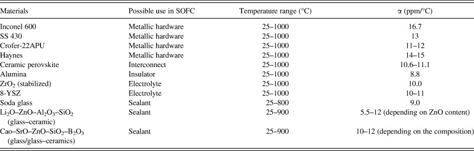
Seals for SOFC can be classified into two main groups based either on brazing or glass sealing. Glass seals can be further subdivided into rigid or compliant seals. Weil et al.Reference Weil, Hardy, Kim and Indacochea13 used alloys like FeCrAlY (Fe 22% Cr, 5% Al, 0.2% Y) as a model metal for sealing by brazing to yttria-stabilized zirconia (YSZ) electrolyte. A large number of studies have focused on using glasses that crystallize either during processing or during use in a SOFC thereby forming a more rigid glass seal.Reference Yang, Xia, Meinhardt, Weil and Stevenson3, Reference Sohn, Choi, Kim, Song and Kim4, Reference Brow and Reis14 These seals are initially hermetic but require close match of the coefficient of thermal expansion (CTE) and are less forgiving against seal fracture under thermal transients/shock. A number of other sealing concepts are also possible for SOFC. Lewinsohn et al.Reference Lewinsohn, Quist and Elangovan15 suggested using polymers of Si–C–N to make seals for SOFC components. Chou and StevensonReference Chou7, Reference Chou, Stevenson and Chick8, Reference Chou and Stevenson16 used a novel approach of mica and mica–glass hybrid compressive seals. LoehmanReference Loehman17 has suggested using glass seals for attaching SOFC components. SinghReference Parihar and Singh10, Reference Singh12 is developing glass–metal seals incorporating a novel self-healing concept. Taniguchi et al.Reference Tanaguchi, Kadowaki, Yasuo, Akiyamu, Miyaki and Nishio18 reported using a combination of glass/YSZ and Fiberfax fiber (alumina fiber) matte to seal the SOFC components. The fiber layer was porous/compliant and provided stress reduction on the electrolyte–electrode assembly via compliance of the fiber layer. Brow and ReisReference Brow and Reis14 developed promising glasses and glass–ceramics for SOFC seals with properties suitable for fabricating rigid seals. The current materials system for the SOFC (Table I) consists of 8% YSZ electrolyte, Ni–YSZ anode, doped lanthanide perovskite cathode, doped chromites/alloys as interconnects, insulating seals, and manifolds made of heat-resistant metallic alloys such as Crofer-22APU and other ferritic steels.
CTE for some useful metallic, ceramic, and glass materials for SOFC.Reference Singh12, Reference Brow and Reis14, Reference Donald19, Reference Kingery, Bowen and Uhlman20

III. A NOVEL APPROACH OF SELF-HEALING GLASS SEAL FOR SOFC
Most of the glass seals developed so far are rigid in nature and require close match in expansion to minimize residual stresses among various materials forming a seal. A novel concept of self-healing glasses, advanced by our research group, can help to alleviate some of the expansion mismatch requirements and still be able to form a functioning seals between materials with a significant expansion mismatch. The rationale behind this novel concept is that at the SOFC operating temperature of 800 °C, a sealing glass with appropriate properties/viscosity can actively heal cracks created during thermal transients. The advantage of this approach is that materials with a significantly different CTE can potentially be used for seals because at the cell operating temperatures, induced thermomechanical stresses can be relaxed via viscous flow.Reference Govindraju, Liu, Sun, Singh and Singh21 However, there are a number of challenges to making a functioning seal using the self-healing concepts and glasses. The first is that the glass must demonstrate self-healing near the cell operating temperature of ∼800 °C, must remain stable against crystallization for a very long time, and must maintain sealing capability. We are pursuing some of the solutions to these challenges by developing self-healing glasses with appropriate thermophysical properties, video imaging to qualitatively demonstrate and study self-healing behavior, and leak testing to further identify and demonstrate self-healing glasses and seals as described below.Reference Singh and Parihar9–Reference Singh12
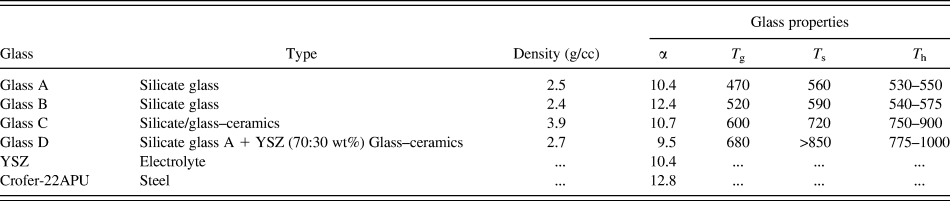
To demonstrate self-healing behavior of glasses, the main criterion for the glass selection was its CTE in relation to the YSZ and a metal. A number of glasses were chosen to ensure close expansion match between glass, YSZ, and metal as shown in Table II. These sealing glasses are all SiO2 based containing a variety of other typical constituents. Glasses A and B are amorphous, glass C crystallizes to 90% crystalline phase during sealing operation around 800 °C, and glass D contained 30% by weight of a crystalline ceramic phase (YSZ). The purpose of having different glasses with and without the crystalline phases was to qualitatively study the effect of crystallization and crystalline phases on the self-healing behavior and associated kinetics. For self-healing study, a crack/scratch was intentionally made on the surface of the glass sample by scratching or indentation, which was placed inside a furnace equipped with a CCD video camera. Video imaging of the crack was monitored and recorded while it was heated at a rate of 5 °C/min to the desired temperature. The self-healing behavior of the cracks was investigated by observing the crack in situ as a function of time and temperature. The start of the healing process was identified by the shrinkage of the crack and the end was characterized by a total disappearance of the crack. The cracks created by indentation simulate both cracks at the surface and in the bulk.
Properties of the selected materials and self-healing behavior.Reference Parihar and Singh10, Reference Singh12
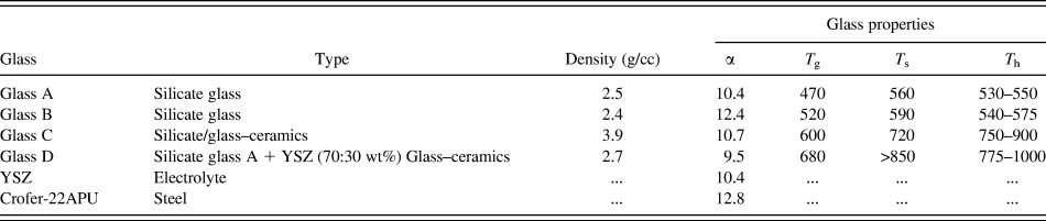
α, CTE (ppm/°C); T g, glass transition temperature (°C); T s, glass softening temperature (°C); T h, glass crack-healing temperature (°C).
The self-healing study of the glasses containing cracks using a video imaging approach showed that glass starts to heal over a wide temperature range (T h) depending on the glass type and the amount of the crystalline phase in the glass as given in Table II. It takes only 5 min above 650 °C for the crack to completely disappear for glasses A and B showing relative stability against crystallization, which indicates that the rate of healing is sufficiently rapid. In contrast, glasses with a significant amount of the crystal phase show relatively sluggish self-healing kinetics (glasses C and D). In fact, the crack healing in glasses containing a significant level of the crystalline phases starts above the glass transition temperature (T g) and in some cases continues well above the glass softening temperatures such as for glass D. These observations have important implications on the self-healing ability of glass seals, i.e., glasses with a large crystalline phase may not be suitable for making seals with an ability to self-heal/repair at the SOFC operating temperature. Nonetheless, glasses with a small amount of the crystal phases and long-term stability against crystallization are potential candidates for making self-healing glass seals. Based on the self-healing studies, the glass B appeared promising for making seals because this glass becomes sufficiently soft at higher temperatures, which enables it to flow and conform to Crofer and YSZ surfaces at seal making and operating temperatures. This glass also remains amorphous after 2000 h exposure at 800 °C, which was confirmed by x-ray studies. The seals were fabricated for testing using this glass.
IV. SELF-HEALING SEAL PERFORMANCE
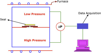
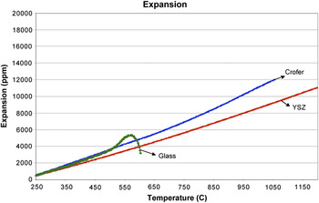
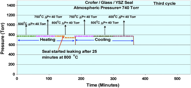
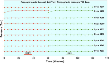
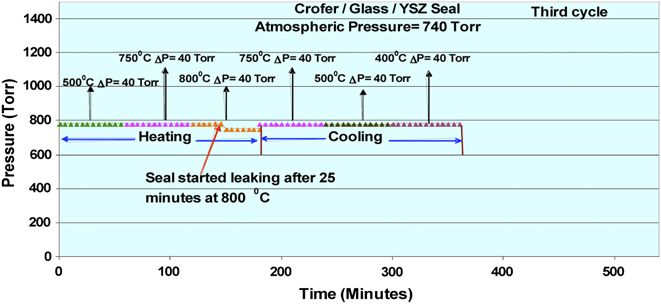
Thermal expansion behaviors of the materials (Crofer, glass B, and YSZ) used for making seals are shown in Fig. 3. These seals were successfully made and tested at room temperature under a pressure drop (ΔP) ∼150 Torr using a setup shown in Fig. 2. These seals were completely leak tight even after 24 h of testing. A seal was tested for leak at higher temperatures during thermal cycling between room temperature and 800 °C. The heating and cooling rates were 5 °C per min and hold temperatures were 25, 500, 750, and 800 °C during thermal cycling. Atmosphere on both sides of the seal was initially argon. After continuous cycling between room temperature and 800 °C for two more cycles, this seal started leaking at 800 °C during the third cycle. To heal the seal, it was kept at 800 °C for 30 min in a seal test stand under no pressure difference across it. In these teats, we did not have the load on the seal area, which will normally be the case in a SOFC stack. Therefore, we did not impose a pressure difference during healing studies. After the healing, this seal became leak tight again as shown in Fig. 4. Subsequent to the healing treatment, this seal remained leak tight for the next 195 thermal cycles between room temperature and 800 °C. Total exposure time for seal at 800 °C was 1185 h. Healing of the seal and its further hermetic behavior demonstrated that this seal could be repaired even if it started to leak, just by keeping it at the cell operating temperature for a short time demonstrating active self-repair. After 195 thermal cycles, there was no degradation in seal hermeticity in argon atmosphere; hence, seal environment was changed to (argon + 4% hydrogen) gas mixture so as to test the performance of the seal under fuel/reducing atmosphere. In the argon + 4% hydrogen atmosphere, seal was tested for another 22 thermal cycles between room temperature and 800 °C. Total exposure of seal at 800 °C under this condition was 400 h. Self-healing of the seal in 271 thermal cycle when leaking in 270 cycle and total exposure time of more than 2500 h as shown in Fig. 5 clearly indicated that these seals are capable of maintaining hermeticity and active self-repairability for a very long time. Testing of the seal continued up to 300 cycles and 3000 h of exposure at 800 °C at which point the test was terminated.
Seal testing setup.

Thermal expansion behavior of Crofer, glass, and YSZ.

High temperatures leak data of the seal tested during third thermal cycle (1 Torr = 133.3 Pa).
High temperatures leak data of the seal in dual atmosphere to 271 cycles and 2900 h (1 Torr = 133.3 Pa).

These results have demonstrated the technological promise of seals for active self-repair under conditions of an operating SOFC. However, what is lacking is a fundamental understanding of the kinetics of crack healing in glass and glass composites (a glass containing particulate inclusions or glass–ceramics created by crystallization of glass). With such an understanding, one can identify the crack-healing mechanism and be able to predict the healing time required to achieve self-repair in a functioning SOFC. In addition, the role of the crystalline ceramic phase in influencing healing behavior can be better understood so that glass composites with optimum load-bearing capability and crack-healing ability can be designed for use as seals in a SOFC.
V. SELF-HEALING BEHAVIOR
While the workability of the active self-repairable glass seals for SOFC is demonstrated, the fundamental mechanism of crack healing responsible for the self-repair is not understood. Consequently, there is a critical need to elucidate the fundamental factors affecting crack healing in glasses and glass–ceramic composites. A lack of such an understanding can prove to be a significant bottleneck toward developing cost-effective seals for SOFCs.
The study of crack healing in ceramics, glasses, and glass composites has been of interest recently in our group for designing self-repairable glass seals for SOFC as described above, and in the past for the possible recovery of mechanical strength, and as a means of studying the fundamental thermodynamic and kinetic phenomena involved. Many studies have shown that cracked ceramics can recover strength partially, or even fully by crack healing, depending on the system and heat treatment.Reference Gupta22–Reference Wiederhorn and Townsend26 Other studies have explored the similarity between crack healing and the early stages of sintering.Reference Nichols and Mullins27–Reference Wilson and Case31 The driving forces, mechanisms of mass transport, and geometries are similar in these situations. If the geometry of cracks can be controlled, the kinetic parameters of healing can be accurately extracted. The majority of studies on the evolution of cracks in materials have been performed on crystalline materials. Some of the crack-healing studies in crystalline systems were summarized in a review paper by Gupta.Reference Gupta32
In amorphous materials like glasses with mass transport by viscous flow, the crack-healing behavior is expected to be different from that of typical crystalline systems. Jagota and DawsonReference Jagota and Dawson33 performed numerical calculations of the sintering of two spheres by viscous flow. In contrast to the behavior in systems controlled by diffusional transport, they calculated that no undercutting will occur. Hence, again making the analogy between this stage of sintering and crack healing, it is not expected that a tubular bulge will develop at the crack tip when transport is by viscous flow. Instead, the crack tip should simply recede, while the crack cross-section approaches a circle. This behavior is actually what is observed in initial observations of crack healing in glasses as described below.
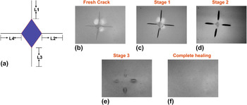
To calculate and compare crack-healing rate of these glasses, accurate determination of the variation in crack length with time at a given temperature is required. An approach of microindentation was used to generate cracks of a well-defined geometry. To achieve this, sintered samples of a glass were polished with 0.5-μm alumina paste. Polished samples were then indented using a Vickers microindenter under a load of 10 N for 15 s. Due to the indentation, four cracks one on each side of the indent were formed on the sample as schematically shown in Fig. 6(a). The average crack length was calculated as arithmetic average of these four crack lengths (L1, L2, L3, and L4). These samples were then heat treated at different temperatures and times in air and fuel (Ar–4% H2–6% H2O) to simulate SOFC environments. During heat treatment, cracks were observed under an optical microscope or in situ using a video recording system,Reference Wang, Anandkumar and Singh34 and crack length was measured as a function of time at a given temperature. The variation in this average crack length with time at a particular temperature was then used and plotted in the graphs to study the crack-healing kinetics. Morphological evolution of the crack with annealing time was also studied using the same approach. Figure 6 also shows an example of the proposed approach to study the kinetics of crack healing in a glass using an optical microscope. Figure 6(b) shows an as-indented glass surface on which four dominant cracks were generated. This indented glass sample was then annealed at 570 °C for different length of times to reveal different stages of crack healing of the glass at 570 °C in Figs. 6(c)–6(f). These preliminary ex situ proof-of-concept experiments resulted data (Fig. 6), which showed that the crack healing of the glass can be divided into three stages. In the first stage, crack tip blunting along with some other changes in the crack morphology are observed, which result in cylinderization of the crack as shown in Fig. 6(c). In the second stage, this cylindrical crack gets filled by viscous flow of the glass and results in spherodization of the crack. In the third stage, the spherical crack cavity also decreases with time [Fig. 6(e)] and results in a crack-free surface [Fig. 6(f)] at the end of the crack healing. This approach was used to study the crack-healing kinetics in a pure glass B.
(a) Schematic of Vickers indented cracks on a glass surface and (b–f) crack-healing behavior of a glass indicating several stages of healing of cracks introduced by microindentation technique. The crack geometry for modeling will be based on actual data such as this (Magnification: 400×).

A model of crack healing is attempted and applied to explain the crack-healing behavior of glasses and glass–ceramic composites. The total time (t) required for crack healing based on three steps (crack tip blunting, cylinderization of crack, and spherodization of crack) shown in Fig. 6 and controlled by viscous flow/creep can be derived as


where K is a constant dependent of crack geometry and surface energy and η is the viscosity of the glass and related to creep behavior.
Therefore, it is clear that the crack-healing response of the glass is directly dependent on the viscosity of the glass. Crack healing in glasses occur over a relatively small temperature range. If the temperature is too low, no or very little crack healing occurs. If temperature is very high, the crack healing is too rapid and could not be studied. So, the temperature range over which crack healing occurs and can be systematically studied falls under a narrow range of about 100–200 °C. For such a narrow range of temperature, it is reasonable to assume that ln (viscosity) linearly changes with temperature (1/T), where T is the temperature in Kelvin. Consequently, a straight-line equation can be used as:
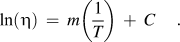
From a dilatometric data of the glass (Fig. 3), the glass transition temperature (T g) and glass softening temperature (T s) can be obtained. Glass transition temperature can be defined as a temperature at which viscosity of the glass is 1011.3 Pa s. Glass softening temperature can be defined as a temperature at which viscosity of the glass is 108.5 Pa s. If these values are used in Eq. (3), one can get the equation for glass viscosity over the glass healing temperature range as:
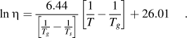
Using Eq. (4), Eq. (2) can be rewritten as

The value of K not only depends on size and shape of the crack but also on the characteristics of the glass. Hence, direct calculation of the value of K for a given crack is not possible and it should be obtained by analyzing experimental data as follows.
For the glass used in this study, T g = 788 K and T s = 838 K, thus, Eq. (5) can be rewritten as

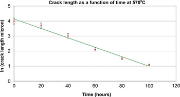
The value of K can be calculated for a glass if healing experiments are done on the glass samples at a fixed temperature. In this case, if the ln (crack length) is plotted against time for this fixed temperature, it should be a straight line. Figure 7 shows a plot between average crack length and annealing time at 843 K (570 °C) consistent with this behavior. Constant K in Eq. (6) can also be calculated using this data from the time required for healing to complete (time coefficient t c) at 570 °C at crack length of zero. Putting these values in Eq. (5) gives K = 2.66 × 10⁻³ Pa. Putting this value of K in Eq. (6) will give an expression for temperature dependence of the time coefficient (t c) as:

Crack-healing dependence on time and calculation of time coefficient based on the model.

Equation (7) can be used to predict the values of time coefficients t c at other temperatures, and these values can be compared with the experimental data. In fact, a plot of ln t c versus T can also provide an independent determination of viscosity of the glass or glass–YSZ composites from the crack-healing data. A comparison of this value with the viscosity values measured from creep data can provide additional independent validity to the analytical model for predicting crack-healing kinetics in glasses and glass–YSZ composites. This is being pursued at the present time.
This model can be used to predict the crack-healing behavior and time required for healing of glasses and glass–ceramics. These results are expected to provide unique opportunity for designing new sealing glasses and glass–ceramic composites useful as seals with self-repair capability for SOFCs and for predicting their self-healing behaviors. The importance of viscous glasses for creating self-repairable glass seals is also evident from our original workReference Parihar and Singh10, Reference Singh12 and recent studies by others in open literature.Reference Chou, Thomsen, Choi and Stevenson35, Reference Zhang, Zou, Zhang, Tang and Yang36
VI. CONCLUDING REMARKS
A brief review of the requirements for SOFC seals was performed. This was followed by the status of seal’s development for SOFC. Based on this information, an attempt was made to formulate an approach for successful seals development utilizing materials selection, thermomechanical modeling, property measurement, processing, and seal testing. In addition, a new concept of self-healing seals was proposed and used for fabricating seals for SOFC. The advantage of the self-healing sealing concept lies in its ability to satisfy conflicting requirements on sealing materials for SOFC as well as for the ability to repair leaking seals in situ. This concept was then used to fabricate seals and to demonstrate self-healing/repair behavior using leak tests. Self-healing behaviors of the glasses as well as of seals made using this glass were clearly demonstrated. Stability of these glass seals under different testing conditions was shown by leak tight responses even after as many as 300 thermal cycles between room temperature and 800 °C. Along with the stability, the glass seals retained their ability to self heal even after very long exposure times of more than 3000 h at higher temperatures.
Self-healing behavior was studied by creating cracks on the glass surfaces and then observing the healing kinetics via a video recording approach at elevated temperatures. Glasses showing stability against crystallization showed rapid crack-healing abilities near the glass softening temperatures. In contrast, glasses containing a significant amount of the crystalline phase showed sluggish healing kinetics even at temperatures much higher than the glass softening temperatures.
ACKNOWLEDGMENTS
The author is grateful to S.S. Parihar for the experimental work described in the paper. This project was partly supported by National Science Foundation under Grant No. DMR-1147812 and U.S. Department of Energy–SECA program through Grant No. DE- DE-09FE001390. Any opinions, findings, conclusions, or recommendations expressed in this material are those of the authors and do not necessarily reflect the views of the National Science Foundation.