1. Introduction
Shock reflection is a typical phenomenon in supersonic flow and has been well studied for single incident shock reflection before (Ben-Dor Reference Ben-Dor2007). When supersonic flow with an inflow Mach number
 $M_{0}\gt 1$
encounters a wedge with the lower wedge surface turning at an angle
 $\theta _{w}$
, an incident shock wave is produced, which will reflect over the reflecting surface. Both regular reflection (RR) and Mach reflection (MR) are possible, depending on
 $ M_{0}$
and
 $\theta _{w}$
. For RR, the incident shock wave only produces a reflected shock wave. For MR, first observed by Mach (Reference Mach1878), the reflection of the incident shock wave produces a reflected shock wave and a strong shock wave named the Mach stem. A triple point connects these three shock waves and issues a slipline. The three shock waves and the slipline separate the flow structure into four regions, the solutions of which in the vicinity of the triple point can be solved by the three-shock theory of von Neumann (Reference Von Neumann1943, Reference Von Neumann1945). In the
 $M_{0}{-}\theta _{w}$
plane, there are two transition curves: the von Neumann condition, below which only RR is possible, and the detachment condition, above which only MR is possible. The region between these two curves is called the double solution domain, where both reflections are possible (Hornung, Oertel & Sandeman Reference Hornung, Oertel and Sandeman1979; Chpoun et al. Reference Chpoun, Passerel, Li and Ben-Dor1995; Vuillon, Zeitoun & Ben-Dor Reference Vuillon, Zeiton and Ben-Dor1995; Ivanov et al. Reference Ivanov, Vandromme, Fomin, Kudryavtsev, Hadjadj and Khotyanovsky2001; Ben-Dor et al. Reference Ben-Dor, Ivanov, Vasilev and Elperin2002).
When the number of incident shocks exceeds one, the problem becomes far more complex. For the special case of reflection with two incident shock waves, the following phenomena have been observed by recent studies (Guan, Bai & Wu Reference Guan, Bai and Wu2018, Guan, Bai & Wu Reference Guan, Bai and Wu2020, Guan et al. Reference Guan, Bai, Lin and Wu2020):
-
(a) both pre-Mach reflection (the first incident shock wave has Mach reflection) and post-Mach reflection (the second incident shock wave has Mach reflection) can be produced;
-
(b) for pre-Mach reflection, the second incident shock wave elevates the Mach stem and may induce inverse Mach reflection below the von Neumann condition. Additionally, the reflected shock of the first incident shock may interact with the second incident shock, producing either type-I or type-II shock interference, resulting in four possible reflection configurations;
-
(c) for post-Mach reflection, the first incident shock wave intersects the Mach stem to produce a type-IV shock interference, which produces a jet penetrating into the flow duct below the slipline.
For the extreme case with an infinite number of incident weak shock waves, isentropic compression waves can be used to approximate these shock waves. The reflection of a centred compression wave can be considered as a limiting case of reflection of multiple incident shocks that converge at the same point on the reflection surface. According to the study on this problem (Bai Reference Bai2024), the double solution domain, with both regular and Mach reflections, of centred compression wave reflection is enlarged compared with single shock reflection. In this case, no clear triple point structure exists, instead, the reflected shock and Mach stem form a smooth curved shock wave.
The study of these two extreme cases (one with two incident shocks and the other with an infinite number of weak incident shocks) demonstrates that increasing the number of incident shocks not only alters the transition conditions but also changes the Mach reflection configuration.
Inlet compression with a single shock reflection suffers from total pressure loss due to the strong shock wave. Isentropic compression has been used in the design of the Busemann inlet (Busemann Reference Busemann1942); however, the full Busemann intake has a very long axial length, which causes heavy viscous losses due to the long boundary layer (Ogawa et al. Reference Ogawa, Moder, Timofeev and Boyce2015). It may be advantageous to consider the intermediate case of using compression by multiple shock waves. Before exploring whether such a design can avoid total pressure loss, it is necessary to study the fundamental question of shock reflection with multiple incident shock waves. In this study, we consider multiple incident shock reflection with a finite number
 $K$
of incident shocks. Figure 1 is a schematic display of shock reflection with multiple incident shocks compared with a single incident shock. In figure 1(b), the turning points are labelled as
 $A_{1},A_{2},\ldots ,A_{K}$
and the angle between each wedge lower surface and the horizontal line is labelled as
 $ \theta _{A_{1}},\theta _{A_{2}},\ldots ,\theta _{A_{K}}$
(wedge deflection angle) and the total wedge deflection angle is labelled as
 $\theta _{w}$
(
 $ =\theta _{A_{K}}$
). For the multiple incident shock case, a series of incident shocks, labelled
 $i_{1},i_{2},\ldots ,i_{K}$
in figure 1(b), with each produced by a local turning of the lower wedge surface, reflect over the reflecting surface. If these incident shocks reflect over the reflecting surface at different points, then each reflection may be considered independently. In this paper, we only consider the case where all the incident shocks reflect at the same point (denoted
 $N$
in figure 1
b). This study bridges the previous studies for two extreme cases:
 $K\leqslant 2$
and
 $K\rightarrow \infty$
. In § 2, we consider the general case where each incident shock has arbitrary strength and estimate the number of possible reflection configurations by counting the possible number of local reflection types at each interaction point. Following the study by Guan et al. (Reference Guan, Bai, Lin and Wu2020) for two incident shocks, type-IV shock interference is one possible local structure when a Mach stem of an incident shock interacts with the upstream incident shocks. Accounting for this possibility, we estimate all reflection configurations in § 2.1. We will also use the case
 $K=3$
to show that, apart from pre-Mach reflection and post-Mach reflection, middle-Mach reflection is also possible in § 2.2. This numerical result indicates a similarity between two different ways of describing the local reflection configuration: type-IV shock interference and type-II shock interference. This similarity analysis will allow us to estimate the number of possible reflection configurations differently in § 2.3.
Reflection configuration (only regular reflection is shown in this figure): (a) single shock reflection; (b) multiple shock reflection.

In § 3, we consider the specific case where the incident shocks are produced by equal variation of (a series of) wedge surface deflection angles. We will derive the conventional von Neumann condition and the detachment condition for each incident shock. The results will be compared with the single incident shock case and the centred compression wave case. Additionally, we provide the numerical results for
 $K=1$
to
 $K=10$
to observe how the reflection configuration depend on
 $K$
.
In § 4, the concluding remarks are provided.
2. Possibilities of shock reflection configuration with multiple incident shocks
2.1. An intuitive estimation of the number of possible reflection configurations
The number of possible reflection configurations can be estimated based on observations from shock reflection with two incident shock waves. According to previous studies (Guan et al. Reference Guan, Bai and Wu2018, Reference Guan, Bai and Wu2020; Guan et al. Reference Guan, Bai, Lin and Wu2020), apart from regular reflection, either the first incident shock or the second incident shock may have Mach reflection. Figure 2 displays all the possibilities. For pre-Mach reflection, as illustrated in figure 2(c), the reflected shock of the first incident shock may interact with the second incident shock to generate either type-I or type-II shock interference (Guan et al. Reference Guan, Bai and Wu2020). For post-Mach reflection, as illustrated in figure 2(b), the first incident shock interacts with the Mach stem of the second incident shock to generate type-IV shock interference. According to Guan et al. (Reference Guan, Bai and Wu2020), pre-Mach reflection, in which the first incident shock wave has Mach reflection, occurs when the first incident shock is much stronger than the second one, and post-Mach reflection, in which the downstream incident shock wave has Mach reflection, occurs when the second incident shock is relatively stronger. It is difficult to provide transition conditions to produce these two types of reflection, since inverse Mach reflection may occur.
Thus, even for the reflection with only two incident shock waves, we may have four possibilities:
-
(1) regular reflection, as shown in figure 2(a);
-
(2) pre-Mach reflection with type-I shock interference and pre-Mach reflection with type-II shock interference (figure 2 c);
-
(3) post-Mach reflection with type-IV shock interference (figure 2 b).
Reflection configurations for two incident shocks: (a) regular reflection; (b) post-Mach reflection; (c) pre-Mach reflection with type-I or type-II shock interferences.

Now, we consider the reflection with three incident shock waves. Inspired by observations from two incident shock waves, the following configurations are possible:
-
(1) regular reflection (figure 3 a);
-
(2) first incident shock Mach reflection or pre-Mach reflection (figure 3 b), with type-I or type-II shock interferences at both interaction points
 $T_{2}$
and
$T_{3}$
, i.e. there are four possibilities for this case;
-
(3) second incident shock Mach reflection or middle-Mach reflection (figure 3 c), with type-I or type-II shock interference at interaction point
$T_{3}$
, and with type-IV shock interference at interaction point
$ T_{1}$
, i.e. there are two possibilities for this case; -
(4) third incident shock Mach reflection or post-Mach reflection (figure 3 d), with type-IV shock interferences at interaction points
$ T_{1}$
and
$T_{2}$
, i.e. there is one possibility for this case.


Thus, there are eight possible reflection configurations for three incident shock waves.
Reflection configurations: (a) regular reflection; (b) pre-Mach reflection; (c) middle-Mach reflection; (d) post-Mach reflection.

Now consider
 $K$
incident shock waves. We possibly have:
-
(1) one regular reflection;
-
(2) first incident shock Mach reflection or pre-Mach reflection, with
$ 2^{K-1}$
type-I or type-II shock interferences at interaction points
$T_{2}$
,
$T_{3}$
,…,
$T_{K}$
; -
(3) second incident shock Mach reflection, with
$2^{K-2}$
type-I or type-II shock interferences at interaction points
$T_{3}$
,
$T_{4}$
,…,
$T_{K}$
, and with type-IV shock interference at interaction point
$T_{1}$
, i.e. in total, there are
$2^{K-2}$
possibilities in this case; -
(4) third incident shock Mach reflection, with
$2^{K-3}$
type-I or type-II shock interferences at interaction points
$T_{4}$
,
$T_{5}$
,…,
$T_{K}$
, and with type-IV shock interferences at interaction points
$T_{1}$
and
$T_{2}$
, i.e. in total, there are
$2^{K-3}$
possibilities in this case; -
(5)
$k\mathrm{th}$
incident shock Mach reflection, with
$2^{K-k}$
type-I or type-II shock interferences at interaction points
$T_{k+1}$
,
$T_{k+2}$
,…,
$T_{K}$
, and with type-IV shock interferences at interaction points
$T_{1}$
,
$T_{2}$
,…,
$T_{k-1}$
, i.e. in total, there are
$2^{K-k}$
possibilities in this case. -
(6)
$K\mathrm{th}$
incident shock Mach reflection or post-Mach reflection, with type-IV shock interferences at interaction points
$T_{1}$
,
$T_{2}$
,…,
$ T_{K-1}$
, i.e. in total, there is one possibility in this case.


Now, we can evaluate the total number (denoted
 $N_{p}$
) of possibilities by summing up the numbers of possibilities for
 $k=1,2,\ldots ,K$
, i.e.
 \begin{equation} N_{p}=1+\sum _{k=1}^{K}2^{K-k}=1+2^{K}\sum _{k=1}^{K}\frac {1}{2^{k}}. \end{equation}
Inserting the obvious expression
 \begin{align} \sum _{k=1}^{K}\frac {1}{2^{k}}= 1-\left ( \frac {1}{2}\right ) ^{K} \end{align}
into (2.1) gives
 \begin{equation} N_{p}=2^{K}. \end{equation}
This shows an exponential increase of
 $N_{p}$
when
 $K$
increases.
2.2.
Numerical results for
$K=3$

Now, we display numerical results for multiple incident shock reflections with
 $K=3$
. The purpose of the simulation is to show that we can produce pre-Mach reflection, middle-Mach reflection and post-Mach reflection, depending on the strengths of the three incident shock waves or the wedge deflection angles
 $\theta _{A_{1}}$
,
 $\theta _{A_{2}}$
and
 $\theta _{A_{3}}$
. The paramaters
 $M_{0}=4$
,
 $\theta _{w}=30^{\circ }$
and
 $g=0.4$
(the relative wedge trailing edge height, defined by
 $g=H_{R}/H_{A_{0}}$
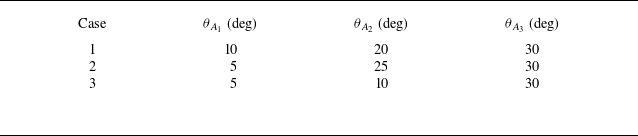
) are shown in table 1. This condition frequently appears in papers related to single shock wave reflection and centred compression wave reflection.
Three cases for numerical simulations, with
 $M_{0}=4$
,
 $ \theta _{w}=30^{\circ }$
,
 $g=0.4$
.

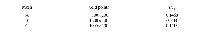
Mach stem height for different meshes.

Numerical simulations are carried out for the compressible Euler equations in gas dynamics, using a second-order Roe scheme on a structure grid, in a similar way as by Bai (Reference Bai2024). To ensure the accuracy of numerical results, we perform a grid convergence study using three different grids of increasing density for
 $M_{0}=4$
,
 $\theta _{w}=30^{\circ }$
,
 $g=0.4$
and
 $K=3$
. Mesh A has 800
 $\times$
200 grid points, Mesh B has 1200
 $\times$
300 grid points and Mesh C has 1600
 $\times$
400 grid points. Table 2 shows the influence of grid density on the distance from
 $T_{1}$
as shown in figure 3 to the reflecting surface (denoted as
 $H_{T_{1}}$
). It can be seen that
 $H_{T_{1}}$
for Mesh B and Mesh C are very close, so we will use a mesh as dense as Mesh B in the following computations.
Case 1 has a large variation of wedge surface deflection angle
 $\theta _{A_{1}}$
. Case 2 has a small variation of wedge surface deflection angle
 $ \theta _{A_{1}}$
, but a large variation of wedge surface deflection angle (
 $ \theta _{A_{2}}-\theta _{A_{1}}$
). Case 3 has a small variation of wedge surface deflection angles
 $\theta _{A_{1}}$
and (
 $\theta _{A_{2}}-\theta _{A_{1}}$
), but a large variation of wedge surface deflection angle (
 $\theta _{A_{3}}-$
 $\theta _{A_{2}}$
). A large variation of wedge surface deflection angle is supposed to induce Mach reflection easier.
The Mach contour lines from the numerical simulations and the enlarged views are all displayed in figure 4. We observe pre-Mach reflection for Case 1, middle-Mach reflection for Case 2 and post-Mach reflection for Case 3.
Mach contourlines for
 $M_{0}=4$
and
 $ \theta _{w}=30^{\circ }$
: (a) Case 1; (b) Case 2; (c) Case 3.

As seen from the numerical result shown in figure 4(a), Case 1 produces a pre-Mach reflection, even though the first incident shock has a wedge deflection angle
 $\theta _{A_{1}}$
below the conventional von Neumann condition. Figure 4(a) also shows an enlarged view around triple point
 $T_{1}$
, where the first incident shock has an inverse Mach reflection, meaning the Mach stem is convex towards the upstream direction. The inverted shock only occurs when the flow condition is in the domain below the conventional von Neumann condition (Hekiri & Emanuel Reference Hekiri and Emanuel2015). This inverse Mach reflection has also been observed in the case of two incident shock waves and is explained using the blunt-body analogy (Guan et al. Reference Guan, Bai and Wu2018). The blunt-body analogy comes from the observation of Roye, Henderson & Menikoff (Reference Roye, Henderson and Menikoff1998), who provided a configuration (see their figure 6b) where an additional blunt body is placed along the reflecting surface and an inverted Mach reflection ahead of this blunt body is observed. The slipline deflects towards the upward direction. The second incident shock interacts with the reflected shock from triple point
 $T_{1}$
to produce a type-I shock interference at interaction point
 $T_{2}$
. Guan et al. (Reference Guan, Bai and Wu2018) showed that type-II shock interference may exist in the case of two incident shock waves. One reflected shock from
 $T_{2}$
reflects again over the slipline at point
 $P_{2}$
, to produce an expansion fan and drive the slipline to change direction, for the reason of pressure balance as discussed by Guan et al. (Reference Guan, Bai and Wu2018) for two incident shock waves. Another reflected shock from point
 $ T_{2}$
interacts with the third incident shock at point
 $T_{3}$
to produce another type-I shock interference, and one reflected shock from
 $T_{3}$
further reflects over the slipline at point
 $P_{3}$
to produce another expansion fan and change the slope of the slipline in a similar way as at point
 $P_{2}$
. The slipline is driven towards the downward direction, so that a convergent-divergent quasi-one-dimensional flow duct can be sustained.
As seen from the numerical result shown in figure 4(b), Case 2 produces a middle-Mach reflection, which means that the second incident shock generates a Mach reflection. Figure 4(b) also offers an enlarged view around the interaction points. The second incident shock has a Mach reflection, and the slipline from triple point
 $T_{2}$
is deflected downwards. In addition, since the incoming flow for the second incident shock is not horizontal, it is difficult to estimate whether it is a reverse Mach reflection from figure 4(b). The first incident shock interacts with the Mach stem from triple point
 $T_{2}$
to produce a type-IV shock interference at interaction point
 $T_{1}$
. The type-IV shock interference consists of two triple points (
 $T_{1}$
and
 $T_{1}^{^{\prime }}$
) and a jet zone (surrounded by the sliplines from the triple points
 $T_{1}$
and
 $ T_{1}^{^{\prime }}$
), which has also been observed in the case of two incident shock waves (Guan et al. Reference Guan, Bai, Lin and Wu2020). As for the third incident shock, it interacts with the reflected shock from triple point
 $T_{2}$
to produce a type-I shock interference at interaction point
 $T_{3}$
.
As seen from the numerical result shown in figure 4(c), Case 3 produces a post-Mach reflection. The flow structure in this case differs from that in Cases 1 and 2, and is magnified in figure 4(c) around the interaction points. The third incident shock has a Mach reflection, and the slipline from triple point
 $T_{3}$
is deflected downwards. It is difficult to estimate whether it is a reverse Mach reflection from figure 4(c) as in Case 2. The second incident shock interacts with the Mach stem from triple point
 $T_{3}$
to produce a type-IV shock interference at interaction point
 $T_{2}$
, which consists of two triple points (
 $T_{2}$
and
 $T_{2}^{^{\prime }}$
) and a jet zone (surrounded by the sliplines from triple points
 $T_{2}$
and
 $T_{2}^{^{\prime }}$
).
2.3. Similarity of apparent different reflection configurations and equivalent number of possible configurations
In § 2.1, for the shock reflection problem with
 $K$
incident shock waves, we have assumed that if the
 $k\mathrm{th}$
incident shock has Mach reflection, then there are
 $2^{K-k}$
type-I or type-II shock interferences at interaction points
 $T_{k+1}$
,
 $T_{k+2}$
,…,
 $T_{K}$
, and type-IV shock interferences at interaction points
 $T_{1}$
,
 $T_{2}$
,…,
 $T_{k-1}$
.
There are
 $2^{K-k}$
possibilities for each
 $k$
, resulting in
 $N_{p}=2^{K}$
possibilities in total. For the special case of
 $K=3$
as considered in § 2.2,
 $N_{p}=8$
.
However, as seen from figure 4(b) or figure 4(c), there are two equivalent ways to count the number of configurations. We only consider Case 2 (figure 4 b) to illustrate this equivalence.
The original way, as discussed in § 2.1, considers the second incident shock generating a Mach reflection (middle-Mach reflection) and the first incident shock interacting with the Mach stem of the middle-Mach reflection, thereby generating a type-IV shock interference.
The equivalent way is to regard the first incident shock as generating a Mach reflection (pre-Mach reflection) and the second incident shock interacting with the reflected shock of the pre-Mach reflection, so as to generate a type-II shock interference. The same is true for Case 3 as shown in figure 4(c) and for more general situations.
Now, we use the equivalent way to recount the number of possibilities of shock reflection. We have:
-
(1) one regular reflection, as before;
-
(2) first incident shock Mach reflection or pre-Mach reflection, with
$ 2^{K-1}$
type-I or type-II shock interferences at interaction points
$T_{2}$
,
$ T_{3}$
,…,
$T_{K}$
. This can be viewed as a pre-Mach reflection followed by a series type-I or type-II shock interferences; -
(3) second incident shock Mach reflection, with
$2^{K-2}$
type-I or type-II shock interferences at interaction points
$T_{3}$
,
$T_{4}$
,…,
$T_{K}$
, and with a pre-Mach reflection at
$T_{1}$
and a type-II (previously regarded as type-IV interference at
$T_{1}$
and a Mach reflection at
$T_{2}$
) shock interference at
$T_{2}$
. In summary, this reflection can be viewed as a pre-Mach reflection, followed by a type-II shock interference and then by (
$ K-2$
) type-I or type-II shock interferences; -
(4) third incident shock Mach reflection, for similar reasons as above, can be viewed as a pre-Mach reflection, followed by two type-II shock interferences and then by (
$K-3$
) type-I or type-II shock interferences. -
(5)
$k\mathrm{th}$
incident shock Mach reflection, for similar reasons as above, can be viewed as a pre-Mach reflection, followed by (
$k-1$
) type-II shock interferences and then by (
$K-k$
) type-I or type-II shock interferences; -
(6)
$K\mathrm{th}$
incident shock Mach reflection, this can be seen as a pre-Mach reflection followed by
$(K-1)$
type-II interference structures.


It is obvious that the possibilities for the second to
 $K\mathrm{th}$
incident shock Mach reflections are all covered by the first incident shock Mach reflection, so the total number, denoted as
 $M_{p}$
, of possibilities is simply given as
 \begin{equation} M_{p}=1+2^{K-1}. \end{equation}
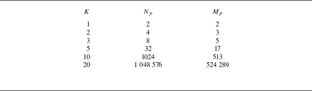
Table 3 provides a comparison between the number of reflection types given by (2.3) and by (2.4). It is seen that the equivalent number is highly reduced compared with the original estimation for very large
 $K$
. Since
 $\frac {1+2^{K-1}}{2^{K}}\approx \frac {1}{2}$
when
 $ K$
is large enough, the number
 $M_{p}$
is approximately half of
 $N_{p}$
.
Dependence of
 $N_{p}$
and
 $M_{p}$
on
 $K$
.

3. Multiple shock reflection for equal variation of a series of wedge surface deflection
3.1. Geometric conditions for equal variation of deflection angle problem
Consider
 $K$
incident shock waves, labelled as
 $i_{k}$
with
 $k=1,2,\ldots K$
, produced by an equal variation of deflection angle
 $\Delta \theta _{w}=\theta _{w}/K$
, at turning points
 $A_{k}$
with
 $k=1,2,\ldots$
,
 $K$
.
First, we will consider the shock properties for each incident shock.
The shock angle
 $\beta _{A_{k}}$
for shock
 $i_{k}$
satisfies the shock relation (for weak solution)
 \begin{equation} \tan \Delta \theta _{w}=f_{\theta }(M_{k-1},\beta _{A_{k}}),\quad k=1,2,\ldots ,K \end{equation}
and
 \begin{equation} f_{\theta }({M,\beta })=\frac {2\left ( {M}^{2}{\sin }^{2}{\beta }-1\right ) }{ \left ( {M}^{2}\left ( \gamma +\cos {2\beta }\right ) +2\right ) \tan {\beta }}. \end{equation}
The Mach number
 $M_{k}$
between shock
 $i_{k}$
and shock
 $i_{k+1}$
is given by the shock relation for Mach number
 \begin{equation} M_{k}=f_{M}(M_{k-1},\beta _{A_{k}}),\quad k=1,2,\ldots ,K, \end{equation}
where
 \begin{equation} f_{M}(M,{\beta )}=\sqrt {\frac {\left ( \gamma -1\right ) {M}^{2}+2}{2\gamma {M} ^{2}{\sin }^{2}{\beta }-\left ( \gamma -1\right ) }+\frac {2{M}^{2}{\cos }^{2}{ \beta }}{\left ( \gamma -1\right ) {M}^{2}{\sin }^{2}{\beta }+2}}. \end{equation}
The pressure between shock
 $i_{k}$
and shock
 $i_{k+1}$
is given by the shock relation for pressure
 \begin{equation} p_{k}=p_{k-1}f_{p}(M_{k-1},\beta _{A_{k}}),\quad k=1,2,\ldots ,K, \end{equation}
where
 \begin{equation} f_{p}(M,{\beta )}=1+\frac {2\gamma }{\gamma +1}\left ( {M}^{2}{\sin }^{2}{ \beta }-1\right ). \end{equation}
Now consider the coordinates of
 $A_{k}$
.
In this paper, the incident shock waves are required to intersect at a common point
 $N(x_{N},0)$
on the reflecting surface, with
 $x_{N}$
determined by
 \begin{equation} x_{N}=\frac {y_{A_{1}}}{\tan \beta _{A_{1}}}=\frac {H_{A_{0}}}{\tan \beta _{A_{1}}}. \end{equation}
Due to this constraint, the horizontal position
 $x_{A_{k}}$
of
 $A_{k}$
satisfies the following relations:
 \begin{equation} \left \{ \begin{array}{l} x_{A_{1}}=0, \\ x_{A_{k+1}}=x_{N}-\frac {y_{A_{k+1}}}{\tan \left ( \beta _{A_{k+1}}+k\Delta \theta _{w}\right ) },\quad k=1,2,\ldots ,K-1. \end{array} \right . \end{equation}
The vertical position
 $y_{A_{k}}$
at each turning point satisfies the following obvious geometrical relations:
 \begin{equation} \left \{ \begin{array}{l} y_{A_{1}}=H_{A_{0}}, \\ y_{A_{k}}-y_{A_{k+1}}=\left ( x_{A_{k+1}}-x_{A_{k}}\right ) \tan \left ( k\Delta \theta _{w}\right ) ,\quad k=1,2,\ldots ,K-1. \end{array} \right . \end{equation}
When
 $x_{A_{k}}$
and
 $y_{A_{k}}$
are given or solved, then (3.8) and ( 3.9) can be used to give the relations
 \begin{equation} x_{A_{k+1}}=\frac {y_{A_{k}}+x_{A_{k}}\tan \left ( k\Delta \theta _{w}\right ) -x_{N}\tan \left ( \beta _{A_{k+1}}+k\Delta \theta _{w}\right ) }{\tan \left ( k\Delta \theta _{w}\right ) -\tan \left ( \beta _{A_{k+1}}+k\Delta \theta _{w}\right ) } \end{equation}
and
 \begin{equation} y_{A_{k+1}}=\left ( x_{N}-x_{A_{k+1}}\right ) \tan \left ( \beta _{A_{k+1}}+k\Delta \theta _{w}\right ) \end{equation}
for
 $x_{A_{k+1}}$
and
 $y_{A_{k+1}}$
, respectively.
When
 $\Delta \theta _{w}\rightarrow 0$
and
 $K\rightarrow \infty$
, all the incident shock waves will be compression Mach waves and we recover the situation considered by Bai (Reference Bai2024).
3.2.
Conventional detachment condition and von Neumann condition for the
$k{th}$
incident shock

For reflection of a single shock wave, the transition between the regular reflection and the Mach reflection is determined by the conventional detachment condition and von Neumann condition. When
 $K\rightarrow \infty$
, the problem reduces to the reflection of a centred compression wave. It has been shown that the double solution domain, which includes both regular and Mach reflections, is enlarged in the case of centred compression wave reflection compared with single incident shock reflection (Bai Reference Bai2024). Now, we look at how the transition conditions depend on
 $k$
for finite values of incident shock waves.
Given
 $M_{0}$
and the wedge deflection angles
 $\theta _{A_{k}}$
at the wedge turning points
 $A_{k}$
, the Mach number
 $M_{k}$
and pressure
 $p_{k}$
in region (
 $k$
) (downstream of the
 $k\mathrm{th}$
incident shock wave) are obtained by solving the shock relations (3.1)–(3.5), recursively up to
 $k$
.
First, we consider the detachment condition.
For a given
 $M_{0}$
, the detachment condition for the
 $k\mathrm{th}$
incident shock, denoted as
 $\theta _{A_{k}}=\theta _{A_{k}}^{(D)}(M_{0})$
, is here equal to the value of
 $\theta _{A_{k}}$
such that the flow deflection angle for the reflected shock of the
 $k\mathrm{th}$
incident shock reaches the detachment angle. If the first to
 $k\mathrm{th}$
incident shocks reflect as a whole to produce regular reflection, then the flow parameters in the region downstream of the reflected shock (with shock angle
 $\beta _{r,k}$
), denoted as region (2), are given by the oblique shock wave relations with flow deflection angle
 $\theta _{A_{k}}$
 \begin{equation} \left \{ \begin{array}{c} \tan \theta _{A_{k}}=f_{\theta }(M_{k},\beta _{r,k}) \\ M_{2,k}=f_{M}(M_{k},\beta _{r,k}) \\ p_{2,k}=p_{1}f_{p}(M_{k},\beta _{r,k}) \end{array} \right . .\end{equation}
The detached angle of the
 $k\mathrm{th}$
incident shock is
 $\theta _{A_{k}}=\theta _{max }(M_{k})$
with
 $\theta _{max }$
determined by
 \begin{align} \tan \theta _{max }=f_{\theta }(M_{k},\beta _{m,k}), \end{align}
where
 $\beta _{m,k}$
is the shock angle of the reflected shock at the condition of detachment and satisfies
 \begin{align} \sin ^{2}\beta _{m,k}=\frac {1}{\gamma M_{k}^{2}}\left ( \frac {\gamma +1}{4} M_{k}^{2}-1+\sqrt {(1+\gamma )(1+\frac {\gamma -1}{2}M_{k}^{2}+\frac {\gamma +1 }{16}M_{k}^{4})}\right ). \end{align}
Now, we consider the von Neumann condition.
The von Neumann condition is here defined as the condition for
 $\theta _{A_{k}}$
, denoted as
 $\theta _{A_{k}}=\theta _{A_{k}}^{(N)}(M_{0})$
, such that the pressure
 $p_{2,k}$
downstream of the reflected shock of the
 $k\mathrm{th}$
incident shock (determined by (3.12)) is equal to the pressure
 $ p_{N}$
downstream of a normal shock wave connecting to the incoming flow, i.e.
 \begin{equation} p_{2,k}=p_{N}=p_{0}f_{p}(M_{0},\frac {\pi }{2}), \end{equation}
where
 $f_{p}$
is given by (3.6).
The transition criteria in the
 $M_{0}{-}\theta _{A_{k}}$
plane for the
 $k\mathrm{th}$
incident shock to have Mach reflection are displayed in figure 5.
The curves for
 $k=1$
correspond to the conventional detachment condition (labelled as
 $1_{st}^{D}$
in figure 5) and the von Neumann condition (labelled as
 $1_{st}^{N}$
in figure 5) for the shock reflection of the first incident shock.
The curves for
 $k=2$
correspond to the conventional detachment condition (labelled as
 $2_{nd}^{D}$
in figure 5) and the von Neumann condition (labelled as
 $2_{nd}^{N}$
in figure 5) for the shock reflection of the second incident shock, and the domain between the detachment condition and the von Neumann condition is larger than the domain for the first incident shock.
The curves for any
 $k$
correspond to the conventional detachment condition (labelled as
 $k_{th}^{D}$
in figure 5) and the von Neumann condition (labelled as
 $k_{th}^{N}$
in figure 5) for the shock reflection of the
 $k\mathrm{th}$
incident shock, and the domain between the detachment condition and the von Neumann condition becomes larger with the increase of
 $k$
.
The curves for
 $k\rightarrow \infty$
correspond to the conventional detachment condition (labelled as
 $\infty _{th}^{D}$
in figure 5) and von Neumann condition (labelled as
 $\infty _{th}^{N}$
in figure 5) for the reflection of a centred compression wave studied by Bai (Reference Bai2024).
Transition criteria in the
 $M_{0}{-} \theta _{A_{k}}$
plane for the
 $k\mathrm{th}$
incident shock.

From figure 5, as
 $k$
increases, the changes in the von Neumann conditions and detachment conditions tend to slow down, because the intensity of the incident shock wave decreases significantly with the increase of
 $k$
. When
 $k$
reaches a certain level, the incident shock wave can even be regarded as a Mach wave. It is also shown that the von Neumann condition for regular reflection is lowered and the detachment condition for Mach reflection is elevated as
 $k$
increases.
Note that figure 5 only provides the von Neumann condition and the detachment condition for the
 $k\mathrm{th}$
incident shock, and these conditions do not consider the effect of interferences by other incident shock waves.
For the same incoming Mach number, to achieve the same flow deflection angle, multiple shock wave compression with a larger
 $k$
results in a larger pressure jump and a smaller Mach number decrease, meaning that increasing
 $k$
and decreasing flow deflection angle achieve the same effect on pressure jump and Mach number decrease. As a result, the transition curves for reflection with a larger
 $k$
could be seen as a shift to the left and compression of the transition curves for reflection with a smaller
 $k$
, and thus enlarging the double solution domain at the same abscissa.
In § 2, we have considered numerical results for multiple incident shock reflections for
 $M_{0}=4$
,
 $g=0.4$
and
 $K=3$
. Here, we still consider these parameters but with equal variation of deflection angle to check the critical conditions shown in figure 5.
First, consider the von Neumann condition. According to figure 5, the von Neumann conditions are
 $\theta _{A_{1}}^{(N)}=20.85^{\circ }$
for the first incident shock,
 $\theta _{A_{2}}^{(N)}=19.82^{\circ }$
for the second incident shock and
 $\theta _{A_{3}}^{(N)}=19.61^{\circ }$
for the third incident shock.
Figure 6(a) displays the numerical results for
 $\theta _{A_{1}}=6^{\circ }$
,
 $\theta _{A_{2}}=12^{\circ }$
and
 $\theta _{A_{3}}=18^{\circ }$
, which are all below the von Neumann conditions for the corresponding incident shocks. As shown in figure 6(a), we only observe regular reflection, as suggested by the transition conditions.
Mach contours with three incident shock waves for
 $M_{0}=4$
: (a)
 $ \theta _{w}=18^{\circ }$
; (b)
 $ \theta _{w}=19^{\circ }$
; (c)
 $ \theta _{w}=21^{\circ }$
.

Figure 6(b) displays the numerical results for
 $\theta _{A_{1}}=6.33^{\circ }$
,
 $\theta _{A_{2}}=12.66^{\circ }$
and
 $\theta _{A_{3}}=19^{\circ }$
, which are also below the von Neumann conditions for the corresponding incident shocks. However, as shown in figure 6(b), the first incident shock produces a Mach reflection even though the wedge deflection angle
 $\theta _{A_{1}}=6.33^{\circ }$
for the first incident shock is well below the von Neumann condition
 $\theta _{A_{1}}^{(N)}=20.85^{\circ }$
. The reason for the advance of transition from regular to Mach reflection is the same as discussed in § 2.2: the blunt-body effect of the downstream incident shock triggers this Mach reflection.
Figure 6(c) displays the numerical results for
 $\theta _{A_{1}}=7^{\circ }$
,
 $\theta _{A_{2}}=14^{\circ }$
and
 $\theta _{A_{3}}=21^{\circ }$
. The wedge deflection angles for the first and second incident shocks are both below the von Neumann conditions, but the wedge deflection angle for the third incident shock is above the von Neumann condition. For this case, we still observe pre-Mach reflection, for the same reason as above.
Next, we will consider the detachment condition. According to figure 5, the detachment conditions are
 $\theta _{A_{1}}^{(D)}=25.61^{\circ }$
for the first incident shock,
 $\theta _{A_{2}}^{(D)}=27.72^{\circ }$
for the second incident shock and
 $\theta _{A_{3}}^{(D)}=28.28^{\circ }$
for the third incident shock.
Figure 7(a) displays the numerical results for
 $\theta _{A_{1}}=9.33^{\circ }$
,
 $\theta _{A_{2}}=18.67^{\circ }$
and
 $\theta _{A_{3}}=28^{\circ }$
, which are all below the detachment conditions for the corresponding incident shocks. As shown in figure 7(a), we can observe regular reflection.
Figure 7(b) displays the numerical results for
 $\theta _{A_{1}}=9.5^{\circ }$
,
 $\theta _{A_{2}}=19^{\circ }$
and
 $\theta _{A_{3}}=28.5^{\circ }$
. The wedge deflection angles for the first and second incident shocks are below the detachment conditions, but the wedge deflection angle for the third incident shock is above the detachment condition. In this case, we can no longer observe regular reflection, but rather a pre-Mach reflection.
Mach contours with three incident shock waves for
 $M_{0}=4$
: (a)
 $ \theta _{w}=28^{\circ }$
; (b)
 $ \theta _{w}=28.5^{\circ }$
.

3.3.
Numerical simulation of shock reflection for various
$K$
, observation of shock interaction train

Figures 8–10 display the Mach contourlines for
 $M_{0}=4$
and
 $\theta _{w}=30^{\circ }$
, with
 $K$
varying from 1 to 10. The purpose is to observe how the reflection configuration, particularly the Mach stem height, depends on
 $K$
. In shock reflection with
 $K=1$
, if
 $g$
is smaller than a certain value so that the reflected shock wave touches the shock-generating wedge, then there is no stable shock reflection (Li & Ben-Dor Reference Li and Ben-Dor1997). Note that with various
 $K$
, we cannot hold the same value for
 $g$
since the
 $g$
required to avoid the reflected shock wave interacting with the wedge lower surface is not the same.
The cases with
 $K=1$
and
 $K=2$
have been studied before and can thus be considered as the familiar ones to start with the discussion on the influence of
 $K$
. For
 $K=1$
, we choose
 $g=0.55$
and observe Mach reflection according to the Mach contourlines shown in figure 8(a). For
 $K=2$
, we choose
 $g=0.45$
and observe a complex Mach reflection according to the Mach contourlines shown in figure 8(b), with three triple points. This situation is regarded as pre-Mach reflection in § 2.1 and in the work of Guan et al. (Reference Guan, Bai, Lin and Wu2020), where the first incident shock has Mach reflection while the second incident shock interacts with the reflected shock to generate type-I or type-II shock interference (see Guan et al. Reference Guan, Bai and Wu2020, for the possibility that both occur under the same condition). According to the discussion in § 2.3, this configuration may also be regarded as post-Mach reflection, with the first incident shock interacting with its Mach stem to produce a type-IV shock interference.
Shock reflection for
 $M_{0}=4$
,
 $ \theta _{w}=30^{\circ }$
; (a)
 $g=0.55$
,
 $K=1$
; (b)
 $g=0.45$
,
 $K=2$
.

We now look at the results for
 $K=3$
to
 $K=6$
, for which the Mach contourlines with
 $g=0.4$
are displayed in figure 9.
For
 $K=3$
, the result is shown in figure 9(a). We have a pre-Mach reflection (a first incident shock Mach reflection, with triple point denoted as
 $T_{1}$
), followed by two type-I shock interferences between the reflected shock from triple point
 $T_{1}$
and the second and third incident shocks.
For
 $K=4{-}6$
, the Mach contourlines are shown in figures 9(b), 9(c) and 9(d), respectively. We have pre-Mach reflections, followed by a type-II shock interference (instead of type I as observed for
 $K=3$
), which is generated by the interaction of the second incident shock and the reflected shock from the triple point
 $T_{1}$
.This is further followed by several type-I shock interferences, which are generated by the interaction of the third to
 $K\mathrm{th}$
incident shocks and the reflected shock from the triple point
 $T_{1}$
.
Shock reflection for
 $M_{0}=4$
,
 $ \theta _{w}=30^{\circ }$
,
 $ g=0.4$
: (a)
 $K=3$
; (b)
 $K=4$
; (c)
 $K=5$
; (d)
 $K=6$
.

We now look at the results for larger
 $K$
, i.e.
 $K=7{-}10$
, for which the Mach contourlines with
 $g=0.4$
are displayed in figure 10. We observe pre-Mach reflection as for smaller
 $K$
, but with the interaction at all the other interaction points being of type-I shock interferences. Thus, the shock reflection begins with a pre-Mach reflection, followed by
 $(K-1)$
type-I shock interferences when
 $K$
reaches a certain value. The reason that we no longer have type-II shock interference is that the increase of
 $K$
weakens the strength of the incident shocks, making it difficult for the second to
 $K\mathrm{th}$
incident shocks to generate type-II shock interference.
Shock reflection for
 $M_{0}=4$
,
 $ \theta _{w}=30^{\circ }$
,
 $ g=0.4$
: (a)
 $K=7$
; (b)
 $K=8$
; (c)
 $K=9$
; (d)
 $K=10$
.

Consider
 $K=6$
, for which we observe type-II interference at point
 $T_{2}$
. The reflected shock from
 $T_{1}$
has a shock angle
 $\beta =19.52^{\circ }$
and the second incident shock has a shock angle
 $\beta =19.52^{\circ }$
, with an upstream Mach number of 3.63. Now, for
 $K=7$
, we observe type-I reflection at point
 $T_{2}$
. The reflected shock from
 $T_{1}$
has a shock angle
 $\beta =18.74^{\circ }$
and the second incident shock has a shock angle
 $\beta =18.74^{\circ }$
, with an upstream Mach number of 3.69. The reflection between two shocks of the same family defines asymmetric shock reflection, as studied by Li, Chpoun & Ben-Dor (Reference Li, Chpoun and Ben-Dor1999). For each inflow Mach number, whether we have type-I or type-II shock interferences depends on the shock angles of the two incident shock waves. However, Li et al. (Reference Li, Chpoun and Ben-Dor1999) only provide transition conditions when the inflow Mach number is 4.96.
The term ‘shock interaction train’ may be used to define the configuration of shock reflection as shown in figures 8–
10. The shock interaction train has a pre-Mach reflection for the first incident shock, followed by a series of type-I or type-II shock interferences for the second to
 $K\mathrm{th}$
incident shocks. Figure 11 provides a schematic display of the shock interaction train, including pure type-I shock interference (figure 11
a), pure type-II shock interference (figure 11
b) and hybrid type I–II shock interference (figure 11
c).
Possible shock interaction train: (a) pure type-I shock interference; (b) pure type-II shock interference; (c) mixed type-I–II shock interferences.

Now, we consider how the Mach stem height depends on
 $K$
. Even for single incident shock reflection, the mechanism to determine the size of the Mach reflection configuration has been considered as a challenging problem, as described by Ben-Dor (Reference Ben-Dor2007) p. 53 and addressed by Hornung & Robinson (Reference Hornung and Robinson1982). They argued that the Mach stem height is affected by the pressure decrease information from the wedge trailing edge expansion fan. Hornung & Robinson (Reference Hornung and Robinson1982) postulated a functional form of the Mach stem height, showing that the relative height of the Mach stem (
 $H_{T}/w$
) depends on
 $M_{0}$
,
 $\theta _{w}$
,
 $\gamma$
and
 $H_{R}/w$
(the relative trailing edge height), i.e.
 \begin{equation} \frac {H_{T}}{w}=f\left(M_{0},\theta _{w},\gamma ,\frac {H_{R}}{w}\right), \end{equation}
where
 $H_{T}$
is the vertical distance from the triple point to the reflecting surface. Actually, according to the geometrical relation
 $ w=(H_{A_{0}}-H_{R})\tan \theta _{w}$
, (3.16) can be rewritten as
 \begin{equation} \frac {H_{T}}{H_{A_{0}}}=f(M_{0},\theta _{w},\gamma ,g), \end{equation}
where
 $g$
(
 $=H_{R}/H_{A_{0}}$
) is the relative trailing edge height. For the present problem, the relative height of Mach stem (
 $H_{T_{1}}/H_{A_{0}}$
) should also depend on
 $K$
, so we would have
 \begin{equation} \frac {H_{T_{1}}}{H_{A_{0}}}=f(M_{0},\theta _{w},\gamma ,g,K), \end{equation}
where
 $H_{T_{1}}$
is the vertical distance from the triple point
 $T_{1}$
to the reflecting surface. The explicit form of (3.18) is rather complex to obtain, since even in the single incident shock reflection problem, the model to estimate
 $H_{T}$
has been a challenging issue that has attracted numerous studies, starting from the work of Azevedo (Reference Azevedo1989) and Azevedo & Liu (Reference Azevedo and Liu1993). The model relies on the use of triple-shock theory, the method to describe the characteristics that bring the trailing edge pressure into the sonic throat below the slipline and a quasi-one-dimensional modelling for the flow below the slipline. Since the pioneering studies by Azevedo & Liu (Reference Azevedo and Liu1993), further elaboration has been considered to improve the modelling (cf. Li & Ben-Dor Reference Li and Ben-Dor1997; Mouton & Hornung Reference Mouton and Hornung2007; Gao & Wu Reference Gao and Wu2010; Bai & Wu Reference Bai and Wu2017; Chernyshov, Savelova & Kapralova Reference Chernyshov, Savelova and Kapralova2021; Choe Reference Choe2022) and to extend it to more complex flows (cf. Schotz et al. Reference Schotz, Levy, Ben-Dor and Igra1997; Grasso & Paoli Reference Grasso and Paoli1999; Shoesmith & Timofeev Reference Shoesmith and Timofeev2021; Vinoth, Sushmitha & Rajesh Reference Vinoth, Sushmitha and Rajesh2022).
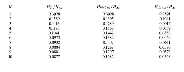
Let us take a look at the specific variation of Mach height with
 $K$
. Table 4 presents the normalised Mach stem height of the first interaction point
 $T_{1}$
(
 $H_{T_{1}}$
/
 $H_{A_{0}}$
), the normalised height of the highest point of the quasi one-dimensional duct (
 $H_{highest}$
/
 $ H_{A_{0}}$
) from
 $T_{1}$
, and the normalised height of the throat of the duct (
 $H_{throat}$
/
 $H_{A_{0}}$
) from
 $T_{1}$
for
 $M_{0}=4$
and
 $\theta _{w}=30^{\circ }$
, with
 $K$
varying from 1 to 10. We choose
 $g=0.55$
for
 $K=1$
,
 $g=0.45$
for
 $K=2$
and
 $g=0.4$
for
 $K=3{-}10$
. So the results for
 $ K=1$
and
 $K=2$
cannot be compared with the results for other
 $K$
due to variations in
 $g$
. From table 4, we can observe the following information:
Variation of several normalised heights with
 $K$
for
 $M_{0}=4$
,
 $ \theta _{w}=30^{\circ }$
.

-
(1) the normalised Mach stem height decreases as
$K$
increases, and the rate of decrease slows down; -
(2) the normalised height of the highest point of the quasi one-dimensional duct decreases as
$K$
increases, and the rate of decrease slows down; -
(3) the normalised height of the throat of the duct decreases as
$K$
increases, and the rate of decrease slows down.


The above variation can be heuristically understood. For the single shock wave reflection problem, when the incoming Mach number
 $M_0$
is fixed, the normalised Mach stem height decreases as wedge deflection angle
 $\theta _{w}$
increases (Gao & Wu, 2024). For the multiple incident shock reflection problem, when the incoming Mach number
 $M_0$
is fixed, increasing
 $K$
and increasing
 $\theta _{w}$
have similar effects based on the parameters downstream of the
 $K\mathrm{th}$
incident shock. For example, both will lead to a decrease in Mach number and an increase in pressure jump downstream of the
 $K\mathrm{th}$
incident shock wave. Therefore, it is inferred that increasing
 $K$
in multiple incident shock reflection will have a similar effect as increasing
 $\theta _{w}$
in single shock wave reflection, that is, causing an increase in the normalised Mach stem height and other similar normalised heights.
Figure 12 shows the variations in normalised Mach stem height
 $ H_{T_{1}}$
/
 $H_{A_{0}}$
as a function of the total wedge deflection angle
 $ \theta _{w}$
for
 $M_{0}=4$
,
 $g=0.4$
and
 $K=1,2,3,5,\infty$
. The normalised Mach stem height decreases as
 $K$
increases in most ranges of
 $\theta _{w}$
. However, there are some intersection points between different lines when the total wedge deflection angle
 $\theta _{w}$
is near the von Neumann condition, indicating that the laws of variation will become complex. In addition, for
 $K=2$
, the normalised Mach stem height varies almost linearly with
 $\theta _{w}$
, similar to
 $K=1$
. As
 $K$
increases, the variation patterns become nonlinear and get closer to the result of
 $K=\infty$
.
Normalised Mach stem height of the first interaction point
 $ H_{T_{1}}$
/
 $H_{A_{0}}$
with
 $M_{0}=4$
,
 $g=0.4$
and different
 $K$
.

Through the transition criteria displayed in figure 5, we can see that for the same inflow Mach number
 $M_{0}$
, a larger
 $K$
results in a smaller von Neumann condition. Therefore, when
 $\theta _{w}$
is small and close to the von Neumann condition, if
 $K$
is less than a specific value, the reflection is in the regular reflection domain, which means the Mach stem height will be zero. If
 $K$
is greater than that specific value, the reflection is in the double solution domain, which means the Mach stem height will be larger than zero. Therefore, when
 $\theta _{w}$
is small enough, the normalised Mach stem height will no longer decrease as
 $K$
increases. This reversal phenomenon of Mach stem height variation has occurred in the reflection of a centred compression wave for the same reason, as shown in figure 13 of Bai (Reference Bai2024). We can see that the Mach stem height for centred compression wave reflection is lower than shock wave reflection in most situations, but it becomes higher when
 $\theta _{w}$
is small enough (approximately
 $21^{\circ }$
for
 $M_{0}=4$
).
4. Concluding remarks
In this paper, we have studied the reflection of
 $K$
incident shock waves in steady supersonic flow, focusing on the case where all the incident shocks reflect at the same point. The total number of possible reflection types is evaluated by counting, at each shock interaction point, the number of possible shock reflections or interference patterns. The von Neumann condition and the detachment condition for multiple shock reflection with equal variation of deflection angles are obtained for each incident shock. Numerical simulations are used to study the shock reflection configuration for
 $K$
up to 10.
The reflection type of multiple incident shocks can be roughly divided into regular reflection and Mach reflection. Mach reflection is very complex because it includes various shock reflection and shock interference structures. If the
 $k\mathrm{th}$
incident shock has Mach reflection and the first
 $(k-1)$
incident shocks generate type-IV shock interaction and the last (
 $K-k$
) incident shocks generate type-I or type-II shock interference, then the estimated number of possible Mach reflection configurations is
 $2^{K}-1$
. However, if we consider the similarity between different configurations, then all the Mach reflections can be regarded as a pre-Mach reflection followed by
 $(K-1)$
type-I or type-II shock interferences, so the total number of possible Mach reflection configurations is reduced to
 $2^{K-1}$
.
For multiple shock reflection with equal variation of deflection angles, we have obtained the transition conditions in the
 $\theta _{w}{-}M_{0}$
plane, from which we see that the von Neumann condition for the
 $k\mathrm{th}$
incident shock is lower than that of classical shock reflection and decreases further as
 $k$
increases, while the detachment condition for the
 $k\mathrm{th}$
incident shock is higher than that of classical shock reflection and increases further as
 $k$
increases, i.e. the region of the double solution domain increases as
 $k$
increases and tends to the region for a centred compression wave reflection when
 $k$
approaches infinity.
Numerical simulations are used to study the Mach reflection structure for
 $ K=1,2,\ldots ,10$
. According to the numerical results, the Mach reflection configuration is a shock interaction train that begins with a pre-Mach reflection and is followed by
 $(K-1)$
type-I–II interference structures. For the condition considered, the normalised Mach stem height decreases as
 $K$
increases while the other parameters are fixed.
The present study bridges the two extreme cases with
 $K=1$
and
 $K=\infty$
. The case with
 $K=1$
is the classical shock reflection one that has been well studied before (Ben-Dor Reference Ben-Dor2007). The case with
 $K=\infty$
has been studied recently for the special case of a centred compression wave (Bai Reference Bai2024), which may be regarded as composed of an infinite number of incident shocks of equal deflection angle.
Funding
This work was supported by the National Natural Science Foundation of China (nos 12472232 and 52192632), the Young Elite Scientist Sponsorship Program by CAST (no. YESS20210042) and the Young Talent Support Plan of Beihang University.
Declaration of interests
The authors report no conflict of interest.