I. INTRODUCTION
Miniaturized bandpass filters (BPFs) with broad stopband have drawn a great deal of attention in recent years. Comparing with typical BPFs, they are more suitable for millimeter-wave and microwave applications, since these filters can effectively improve the linearity of the front-end and reduce the bit error rate of communication systems taking advantage of their capacity of better suppressing harmonic products and spurious signals [Reference Hong and Lancaster1].
So far, various types of methods have been utilized to implement BPFs with wide stopband [Reference Lin, Deng, Lin, Wang and Chen2–Reference Chang and Tam22]. According to their operation mechanism, these reported design methods can be mainly classified into four categories. The first one uses stepped-impedance resonators (SIRs) to push the high-order modes far away from the passband and to relocate the high-order modes of each resonator at dissimilar frequencies, such as quarter-wavelength SIRs [Reference Lin, Deng, Lin, Wang and Chen2, Reference Chen, Chang, Chang and Hung3], half-wavelength SIRs [Reference Chen, Huang and Wu4–Reference Worapishet, Srisathit and Surakampontorn6] or modified SIRs [Reference Peng, Hong, Dai, Tang, Hao, Chen and Wu7–Reference Wu and Hsu10]. Generally, each SIR of these BPFs need to be precisely specified, not only to form the bandpass response but also to prevent the high-order modes from constructing the spurious bands. The second category is to use coupled-resonator circuits to cancel the high-order modes [Reference Kuo, Chen and Jiang11–Reference Zhang and Xue14]. In [Reference Kuo, Chen and Jiang11, Reference Kuo, Jiang and Chang12] the second harmonics were removed by equalizing modal phase velocities. In [Reference Belyaev, Serzhantov, Tyurnev, Leksikov and Bal'va13], quarter-wavelength resonators were arranged in a double-layer suspended substrate to cancel the high-order mode currents. In [Reference Zhang and Xue14], using discriminating coupling, the second harmonic was blocked. The third category utilizes some bandstop structures, such as loading short-stub [Reference Luo, Ma and Li15], open-stub [Reference Tang and Chen16], defected ground structures (DGSs) [Reference Ren and He17], or employing transversal filters [Reference Shi, Feng, Che and Xue18, Reference García, Soriano, Renedo, Penalva and Bronchalo19], to generate the transmission zeros (TZs) which can effectively suppress the spurious responses. The last category is directly cascading low pass filters (LPFs) into the designed BPF to achieve a harmonic-suppressed BPF [Reference Shi, Feng, Che and Xue18–Reference Chang and Tam22]. In [Reference Chaudhary, Jeong and Lim20, Reference Chaudhary, Jeong and Lim21], DGSs with a lowpass property were used at input/output feeding line to suppress the harmonics. In [Reference Chang and Tam22], the stopband is extended by combining square half-wavelength SIR and compact harmonic suppression cell.
Even though they can meet the requirement of some practical applications, it has to admit the filters, developed from the above four methods that suffer from many drawbacks. The first category [Reference Hong and Lancaster1–Reference Wu and Hsu10] need to separately design each SIR, which is complex and labor intensive. For the second category, the main problem lies in only removing second harmonics [Reference Kuo, Chen and Jiang11, Reference Kuo, Jiang and Chang12, Reference Zhang and Xue14] or requiring a three layer suspended circuit [Reference Belyaev, Serzhantov, Tyurnev, Leksikov and Bal'va13]. Compared with the first one, the second category can obtain higher rejection level but less stopband extension. In the third and fourth categories [Reference Luo, Ma and Li15–Reference Chang and Tam22], both the bandstop structures and additional LPFs would increase the in-band insert loss (IL). Furthermore, DGSs [Reference Ren and He17, Reference Chaudhary, Jeong and Lim20, Reference Chaudhary, Jeong and Lim21] or multi-layer structures [Reference Peng, Hong, Dai, Tang, Hao, Chen and Wu7, Reference Packiaraj, Ramesh and Kalghatgi9, Reference Kuo, Jiang and Chang12, Reference Belyaev, Serzhantov, Tyurnev, Leksikov and Bal'va13] or coplanar waveguides (CPW) [Reference Luo, Ma and Li15] are required, which will bring a series of package and fabrication problems. Besides, the circuit size of transversal filter [Reference Shi, Feng, Che and Xue18, Reference García, Soriano, Renedo, Penalva and Bronchalo19] is bulky, due to at least two paths to form the constructive signal-interference.
To address the aforementioned issues, a good way is employing a cascaded LPF-HPF type BPF [Reference Xu, Ji, Wu and Miao23], which, benefiting from LPF construction, can achieve an ultra-wide harmonic suppression and a wide passband. However in [Reference Xu, Ji, Wu and Miao23], the radial stubs are used and detailed TZ and transmission poles (TP) analysis are lacking, so it has not been fully explored and some subtle design issues remain to be addressed. In this paper, a new LPF-HPF type BPF is presented. The LPF is constructed by four SIR stubs with a high-impedance microstrip line (HIML), while the HPF is form by adding two shorted stubs. Moreover, two methods, LEC method and equivalent transmission line circuit (ETLC) method, are adopted to discuss the proposed configuration. As a result, the LEC can be simplified on the one hand, the mechanism of stopband rejection can be easily understood on the other. To validate the proposed method, a BPF characterized by an ultra-wide stopband up to millimeter wave band, more degrees of TZ adjusting freedom, and a low in-band IL is designed and experimentally studied.
This paper is organized as follows. The LEC of the proposed BPF is used for in-band analysis and the ETLCs of the BPF are utilized for full-band analysis in Sections II and III, respectively. The relationship between high frequency model and low frequency model are discussed in Section IV. In Section V, a wideband BPF with very broad stopband is implemented. Finally, the conclusion is drawn.
II. IN-BAND ANALYSIS
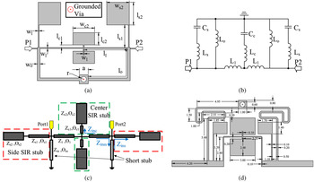
LEC method is of great significance to predict the frequency response and carry out parametric studies, especially for low frequency circuits. To investigate the in-band characteristics of the proposed filter with ease, LEC method is adopted. Specifically, there are only a passband and two TZs that need to be discussed within the concerned operating frequency range. Figure 1(a) shows the proposed geometric structure, which can be equivalent to the lumped circuit model given in Fig. 1(b). In the following, the element model will be derived and investigated based on the proposed LEC.
Proposed filter: (a) geometric structure; (b) low frequency LEC; (c) full band ETLC; and (d) layout sketch (unit: mm).

A) Element model
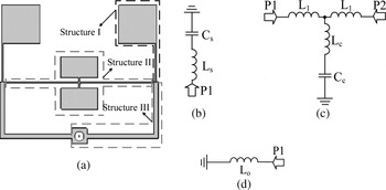
Figure 2(a) shows the parameters of a SIR stub section (structure I), which can be simply modeled as a shunt series-resonant branch, as shown in Fig. 2(b) approximately, when the electrical length is less than a quarter-wavelength [Reference Bahl24, Reference Ma and Yeo25]. The structure II, shown in Fig. 2(a), demonstrates a SIR stubs loaded HIML, which exhibits a lowpass property. This structure can be approximately modeled as lumped elements, shown in Fig. 2(c) under the condition of the effective electrical length smaller than a quarter-wavelength. The short-stub which is plotted in Fig. 2(a), has a highpass property. It can be modeled as a shunt inductance, as shown in Fig. 2(d), when the effective electrical length is far less than a quarter-wavelength.
Three sections of the proposed filter and their LECs: (a) the geometric structures; (b) the LEC of side SIR stub (structure I); (c) the LEC of SIR stubs loaded HIML (structure II); and (d) the LEC of short-stub (structure III).

The values of the lumped elements, L 1 L o , Ls, Cs, Cc , and L c can be calculated by (1), discussed in [Reference Hong and Lancaster1],
 $$\eqalign{L & = \displaystyle{{Z\sin \;\left( {{{2\pi f \times l\sqrt {\varepsilon _{eff}}} / c}} \right)} \over {2\pi f}},\cr & \quad C = \displaystyle{{\tan \left( {{{2\pi f \times l\sqrt {\varepsilon _{eff}}} / c}} \right)} \over {2\pi f \times Z}},\quad \left\{ {\matrix{ {C_c = C \times 2} \cr {L_c = L/2} \cr}} \right.,}$$
where l is the physical length of each line, Z represents the characteristic impedance of the associated transmission lines, c denotes the light speed in free space, and ε eff refers to the effective dielectric constant of the substrate, respectively.
B) Characteristic of the presented LEC
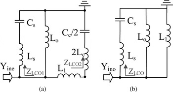
To investigate the in-band response, the LEC of the filter with the fewest number of circuit elements is presented in Fig. 1(b). The element values are calculated by (1)–(3). Since the LEC is the symmetrical physical-based model, the even- and odd-mode equivalent circuits can be derived from the LEC, given in Figs 3(a) and 3(b). Two TZs can be attained to effectively sharpen the upper skirt of the passband and extend the stopband, when the shunt series-resonant branches resonate (Z LCO1 = 0 or Z LCO2 = 0) at a certain frequency (f LOZn , n = 1, 2). The resonant frequencies can be calculated as:
 $$f_{LCOn} = \displaystyle{1 \over {2\pi \sqrt {L_{s/c} C_{s/c}}}}. $$
Fig. 3. Proposed LEC: (a) even-mode LEC; and (b) odd-mode LEC.
Proposed LEC: (a) even-mode LEC; and (b) odd-mode LEC.

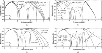
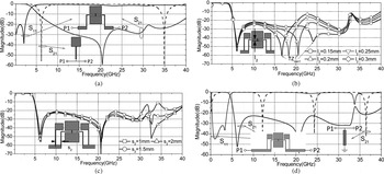
The ideal lumped circuit(|S 11|2 + |S 21|2 = 1), is helpful to understand the in-band operating mechanism of the proposed filter. As shown in Fig. 4(a), the increase of L 1 will make the upper cutoff frequency shift to the high frequency area while it has little influence on the TZs and the lower skirt. However the insert loss (S 21) will increase with the increase of L 1, since the upper skirt becomes sharper and the distance between second pole and third pole becomes wider. As a matter of fact, the SIR stubs loaded HIML (structure II) in Fig. 2(a) can be regarded as a third-order lumped LPF, as shown in Fig. 2(c), which dominantly determines the upper cutoff frequency in the proposed filter. Hence, L 1 can affect its 3 dB cutoff frequency with C c . As shown in Fig. 4(b), the increase of L o makes lower cutoff frequency shift to the low frequency area while it almost does not affect the upper skirt. Changing L o can tune the cutoff frequency in the lower skirt, since the short-stub modeled shunt inductances which has a highpass property, provide the filter with a lower skirt in the passband. Therefore, adjusting L o and L 1 is a good way to tune the cutoff frequencies in the lower and the upper skirts of the passband, respectively, which results in tuning the bandwidth. Besides, reducing L o leads to the highpass loading effect shifting towards lower frequency and its impact on the passband becoming weaker, hence the insert loss is determined by LPF. Therefore increasing L o will reduce the insert loss in a certain range. The resonance of L s and C s , extracted from side SIR stub, provides a TZ in upper stopband resulting in a steeper upper skirt. When L 1 increases, the TZ will shift to the low frequency area and the upper skirt will become steeper while the bandwidth is almost unchanged, as shown in Fig. 4(c). Whereas, shifting the TZ to low frequency to obtain a sharp upper skirt is at the cost of the deterioration of the in-band performance (the insert loss will increase). The frequency responses of the synthesized LECs with different TZ are depicted in Fig. 4(d), where the return loss (RL or S 11) will increase dramatically when TZ moves to the low frequency area and upper skirt becomes steeper.
Transmission and reflection characteristics of the filter. (a) Different upper cutoff frequency; C c = 1.4 pF, L s = 0.93 nH, C s = 0.66 pF, and L o = 7.3 nH. (b) Different lower cutoff frequency; L 1 = 2.92 nH, C c = 1.4 pF, L s = 0.93 nH, and C s = 0.66 pF. (c) Different upper skirts; L 1 = 2.92 nH, C c = 1.4 pF, L s = 0.93 nH, and L o = 7.3 nH. (d) Well-matched (synthesized) filter with different TZ; L 1 = 2.92 nH, C c = 1.4 pF, and L o = 7.3 nH.

III. FULL-BAND ANALYSIS
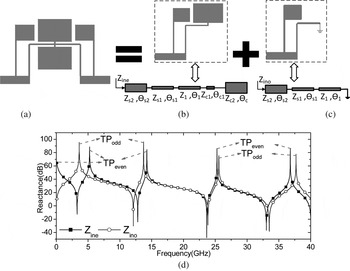
To investigate the full-band response of the filter, not only the performance of the passband but also the locations of the TZs in the stopband need to be taken into account. However the full-band LEC of the proposed filter will be very complicated, which results in a series of problems, such as lack of accuracy or increasing complexity in the analysis. Hence, ETLC method is utilized to discuss the stopband rejection mechanism of the center SIR stubs loaded HIML and to investigate the effect of loading the side SIR stubs. Then, the influence of loading the short-stub is discussed. As shown in Fig. 1(c), the ETLC of the proposed filter consists of four SIR stubs loaded HIML and two short-stub. The short electrical length of the HIMLs perturbation in the center SIR stubs brings a crucial benefit to the filter which will be discussed later.
A) Multi-SIR stub loaded HIML
Multi-SIR stub loaded HIML, as shown in Fig. 5(a), is the most significant part of the proposed filter, which exhibits a lowpass response with a very broad stopband and a sharp skirt. Based on these properties, the desired BPF can be implemented easily by adding highpass structures. Therefore, the investigation of multi-SIR stub loaded HIML is very helpful to understand the operating principle of the harmonic suppression in the presented BPF.
TPs analysis: (a) configuration side SIR stubs and SIR stubs loaded HIML; (b) even-mode; (c) odd-mode; and (d) even-/odd-mode frequency-impedance response.

TPs: even-odd mode analytical method is adopted to roughly investigate the characteristics of high order TPs which are treated as out-band harmonic response. The even-/odd-mode ETLCs are depicted in Figs 5(b) and 5(c). Under the resonant condition, they are subject to
 $$\eqalign{\displaystyle{{Z_{s2}} \over {Z_1}} & = \left[ {\displaystyle{{\left[ {\left( { - Z_{c2} /Z_1 \cot {\theta}_{c2}} \right) + \tan \left( {{\theta}_1 + {\theta}_{s1} + {\theta}_{c1}} \right)} \right]} \over {\left[ {1 + \left( {Z_{c2} /Z_1 \cot {\theta}_{c2}} \right) \tan \left( {\theta _1 + \theta _{s1} + \theta _{c1}} \right)} \right]}}} \right] \cr & \quad \times \tan {\theta}_{s2},}$$
 $$\displaystyle{{Z_{s2}} \over {Z_1}} = \left( {\tan \left( {{\theta}_1 + {\theta}_{s1}} \right)} \right)\tan \theta _{s2}.$$
Then, the frequency-impedance responses can demonstrate the characteristics of the even- and odd-mode ETLCs, shown in Fig. 5(d) where the first odd-mode and the first two even-modes are employed to form the lowpass response. It can be observed the high order even- and odd-mode TPs are arranged in pairs, which means the high order harmonics can be easily suppressed by properly arranging the TZs. It should be noted in Fig. 5(d) that the valleys (Z in = 0) in the impedance curves are unrelated to the resonances.
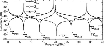
TZs: The TZs are introduced by loading the λ/4 SIR stubs, plotted in Fig. 1(c). When the input impedance of each stub is equal to zero (Z ins = 0 or Z inc = 0), the TZs will be introduced, which can be determined by
 $$\displaystyle{{Z_{c2}} \over {Z_{c1} - \tan \theta _{c1} \tan \theta _{c2}}} = 0,$$
 $$\displaystyle{{Z_{s2}} \over {Z_{s1} - \tan \theta _{s1} \tan \theta _{s2}}} = 0.$$
The parameters R z1 = Z s2/Z 1, R z2 = Z c2/Z 1, α c = θ c2/(θ c1 + θ c2), and α s = θ s2/(θ s1 + θ s2) are adopted to simplify the calculation. The impedance response is shown in Fig. 6.
TZs analysis.

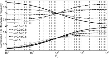
Characteristic of the TPs and the TZs: a good prediction of the required parameters R z , α, and θ t (θ t is total electrical length) to give the desired frequencies of TZs for λ/4 SIR stubs, can effectively extend the stopband. Figure 7 shows the relationship between the normalized resonance frequency (θ t /0.5π) and R z for TZs. It can be observed the desired frequencies of the first mode and the second mode can be specified by selecting appropriate R z , α, and θ t .
Normalized frequency versus impedance ratio for λ/4 SIR stubs for TZs.

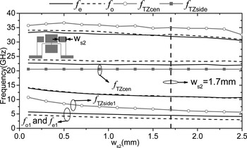
Extracted by Ansoft's HFSS software package, the variations of the TPs and the TZs with different w s2 are depicted in Figure 8. They are helpful to understand the mechanism of the stopband rejection and to adjust the passband response. It can be observed that, with the variation of w s2 the TZs and the TPs are either almost unchanged or changing together within a narrow space. However when w s2 increases, the first-order TZ side (f TZside1) (the side stubs produces two TZs, named f TZside1 and f TZside2) decreases distinctly in the high frequency area above f e1 and f o1, while f e1 and f o1 are keeping unchanged. This is a remarkable advantage on designing the passband formed by f e1 and f o1, because properly choosing w s2 can attain an appropriate location of the first-order TZ (f TZside1) without affecting the other out-band response, which results in a steep upper skirt of the passband and an acceptable in-band RL, as discussed in Section II.
Variation of the extracted TPs and TZs versus ws2.

B) Lowpass property and microstrip short-stub
Since the SIR stubs loaded HIML (structure II) has a lowpass property, employing this structure and the side stubs (structure I) can construct a steep skirt LPF. The operating mechanism is demonstrated in Fig. 9(a) that the SIR stubs loaded HIML provides a TZ and a passband while the side stubs provide the other two TZs. Besides, this property can be observed from the impedance responses of the even- and odd-mode circuits in the Fig. 5(d). Furthermore, since an even-mode resonance (f e0) occur at zero frequency (DC), employing f e0, f e1, and f o1 can easily form a lowpass response.
Operating mechanisms of the proposed filter: (a) operating mechanism of the sharp skirt LPF with ultra-wide stopband; (b) regulating mechanism of the low frequency stopband with different l 2; (c) regulating mechanism of the high frequency stopband with different s 2; and (d) operating mechanism of loading short-stub.

The effect of the short HIML perturbation, in the center SIR stub, on stopband rejection is displayed in Fig. 9(b). It is obvious that when the length of l 1 increase slightly, the frequency (f TZcen ) of the TZ cen will decrease dramatically whereas it almost has no influence on the other frequency response. This is a significant benefit to design broad stopband BPF, because by independently tuning TZ cen the unaligned harmonic resonance can be suppressed without affecting the passband. Additionally, the parasitic coupling (s 2) between center SIR stubs and side SIR stubs can be utilized to improve the high frequency stopband rejection. As displayed in Fig. 9(c), a good stopband rejection about 35 GHz is obtained, when a suitable parasitic coupling strength is chosen.
For the sake of constructing the desired passband response the short-stub are added, which provide a TZ at zero frequency to make DC and lower frequency shorted to ground. The operating mechanism of the passband is illustrated in Fig. 9(d). Moreover as shown in Fig. 7, when the input impedance of the short-stub equals to zero, Z inss = 0, a series of TZs will be produced, which can be calculated as
 $$f_{TZshort} = \displaystyle{{n \times c} \over {2l_o \sqrt {\varepsilon _{eff}}}}, \quad n = 0,\;1,\;2,\;3 \ldots.. $$
Thereby l o can easily control not only the upper cutoff frequency in the passband as discussed in Section II, but also the location of the high order f TZshort in the stopband. Nevertheless, the former one is more important, since the stopband of the proposed filter is dominantly determined by the SIR stubs loaded HIML (structure II) and the side SIR stubs (structure I).
IV. COMBINATION OF IN-BAND ANALYSIS WITH FULL-BAND ANALYSIS
To further investigate the proposed filter, it is necessary to combine the in-band analysis with the full-band analysis, which means to study the relationship between the LEC and the locations of the TZs. According to (4a), (4b), and (5), the locations of the TZs can be determined by θ c2, θ s2, α c , αs, Rz 1, R z2, and l o . In order to carry out the relationship study, the lumped elements in the LEC can be rephrased by
 $$L_c = \displaystyle{{Z_{c2} \sin \left( {\theta _{c2} (1 - \alpha _c )/\alpha _c} \right)} \over {2\pi fR_{z2}}}, $$
 $$C_c = \displaystyle{{\tan \theta _{c2}} \over {2\pi fZ_{c2}}}, $$
 $$L_s = \displaystyle{{Z_{s2} \sin \left( {\theta _{s2} (1 - \alpha _s )/\alpha _s} \right)} \over {2\pi fR_{z1}}}, $$
 $$C_s = \displaystyle{{\tan \theta _{s2}} \over {2\pi fZ_{s2}}}, $$
 $$L_o = \displaystyle{{Z_{ss} \sin \theta _{ss}} \over {2\pi f}}.$$
Thus, when θ c2, θ s2, α c , αs, Rz 1, and R z1 are constants (all locations of the TZs are fixed), the L c and C c can be controlled by Z c2, while L s and C s can be controlled by Z s2, respectively. As a result, the L c , Cc, Ls , and C s can be tuned separately without effect on TZs. Similarly, when the location of the TZ short s are preset (l o is constant), Z ss can independently control L o without influence on the other elements.
V. BPF DESIGN AND MEASUREMENT
Based on the proposed method, a prototype of such filter is presented in this section. The whole BPF structure should be optimized by HFSS and ADS. The tuned physical dimensions are shown in Fig. 1 (d). The design and optimization procedures can be summarized as follows.
According to the synthesized element values, the equivalent lumped circuit (ELC) of the SIR stubs loaded HIML (structure II) can be implemented by using (1)–(3) with the physical dimensions. Based on (6) and (7), tuning α c , Rz 2, and Z c2, allocates the TZ cen near the center of the desired stopband (less than 15 f 0). After optimization by high frequency structural simulator (HFSS), the LPF can be achieved.
By properly selecting α s and R z1 to add side stubs (structure I) according to (4b), a steep skirt and an ultra-wide stopband can be achieved, while choosing suitable Z s2 to fulfill the synthesized element values of the side stubs, based on (8) and (9). After optimization and slightly tuning l 2 and s 2, the LPF with sharp skirt and ultra-wide stopband is achieved.
According to the synthesized element values, the ELC of the short-stub (structure III) can be implemented by using (1) with the physical dimensions. Then, Z ss and l o are tuned slightly based on (3) to prevent the harmonics. After optimization, the desired BPF is achieved.
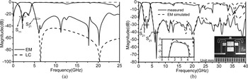
The design procedures of the proposed filter are illustrated in Fig. 9. To consolidate the theory and the discussion, a BPF is designed and fabricated on RT/duroid 5880 with thickness of 0.254 mm and dielectric constant of 2.2. The size of this filter is 0.137λ g × 0.096λ g , where λ g is guided wavelength at 2.8 GHz. The simulated/measured responses of the designed BPF with its photograph are shown in Figs 10(a) and 10(b). It can be observed, the frequency responses of the LEC are in close agreement with the full-wave electromagnetic (EM) simulation in the low frequency area, and the measured results well-match with simulated results in the whole microwave band. Calculated and optimized values for lumped-equivalent circuit are listed in Table 1. It is noted that the discrepancies in Table 1 are mainly caused by parasitic effects, such as the grounded vias and the parallel line coupling.
Simulated and measured results of the proposed BPF: (a) full-wave EM and the LEC simulated results; and (b) full-wave EM and measurement result.

Calculated and optimized values for LEF (Units: C, pF; L, nH).

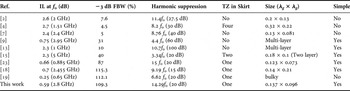
As shown in Fig. 10(b), the fabricated filter has −3 dB cutoff frequencies of about 1 and 4.4 GHz (−3 dB fractional bandwidth (FBW) is 109.3%). The measured IL are less than 1 dB (including the loss from subminiature version A (SMA) adaptors) from 1.4 to 4 GHz (0.59 dB at center frequency 2.8 GHz), and the upper rejection are 20 dB from 5.1 to 40 GHz (1.82–14.29f 0, f 0 denotes the center frequency of −3 dB FBW as shown in Table 2). The mismatches between simulation and measurement are attributed to the substrate permittivity fluctuation and the fabrication tolerance which are more obvious in high frequency, especially at the resonant frequency such as near 20, 25, and 35 GHz.
Comparison between the proposed filter and other filters.

VI. CONCLUSION
A wideband BPF with an ultra-wide upper stopband is proposed and investigated in this paper. The in-band response which exhibits a wide passband and steep skirt properties is treated as a lumped-circuit, while the controllable TZs employed to extend the stopband up to millimeter wave band are extracted from the ETLC. Combined these two analysis, the optimization procedures of this kind of filter are summarized to raise the design efficiency and the design accuracy. Besides, this type of planar filter also exhibits the merits of compact size and no lumped elements are needed. These demonstrate that the proposed filter is a promising candidate for low cost and high-yield millimeter wave applications.
ACKNOWLEDGEMENTS
The authors would like to thank the editors and reviewers of this paper's manuscript for their constructive comments and suggestions, which greatly improved the quality of this paper.
 Di Lu was born in Yunnan province, China, in 1987. He received his B.S. degree in Electronic Engineering School from Chengdu University of Information and Technology (CUIT), China, in 2013. He is now pursuing his Ph.D. in University of science and Technology of China (UESTC). Since October 2015, he has been a Visiting Student with the University of Virginia(UVA). His main research interests are design microwave filters, tunable filters, frequency multipliers, mixers, millimeter-wave circuits, and RF MEMS.
 Xiao-hong Tang received his B.S. and Ph.D. degree in Electromagnetism and Microwave Technology in UESTC. Now he is professor in UESTC. He has authored more than 100 journal and conference papers. He was also the recipient of several national and provincial awards. His research interests include microwave and millimeter communication, computational electromagnetics, etc.