Introduction
Vitrification is used by various countries around the world to immobilize high-level radioactive waste (HLW) in a glass matrix. This wasteform generally has an amorphous structure, although it can also incorporate crystalline regions. The composition of these glasses is complex: HLW contains around 30 fission products, and the exact composition can vary depending on the origin. These fission products are radioactive, and the decay of these species involves a variety of pathways. Alpha, beta, and gamma radiation will produce electronic effects, which involve excitation of electrons. Alpha decay also causes recoil of the parent atom. Both the recoil nucleus and the alpha particle itself generate ballistic collisions where the incident ion interacts with the nucleus of the target atom. There are many outstanding questions regarding the effects of radiation on HLW glass [Reference Weber, Ewing, Angell, Arnold, Cormack, Delaye, Griscom, Hobb, Navrotsky, Price, Stoneham and Weinberg1].
These mechanisms can create defects in the glass structure, which can cause the glass to swell or compact depending on the composition of the glass. Swelling, and the associated decrease in density, can lead to more free space (interstitial sites) in the glass [Reference Kerrache and Delaye2]. The radiolytic breakdown of the glass can also generate gas molecules. These can diffuse through the glass and become trapped in these interstitial sites. The number of interstitial sites is related to the solubility of the gas and, once all interstitial sites are filled, gas molecules can cluster and so could form bubbles [Reference Shackleford3]. The complexity of the glass composition and structure and the variety of mechanisms of radioactive decay provide a challenge for studying bubble formation. It is important to understand this phenomenon, so that the long-term behavior of this wasteform can be characterized. This information can be used to make decisions on how the waste is handled in the future.
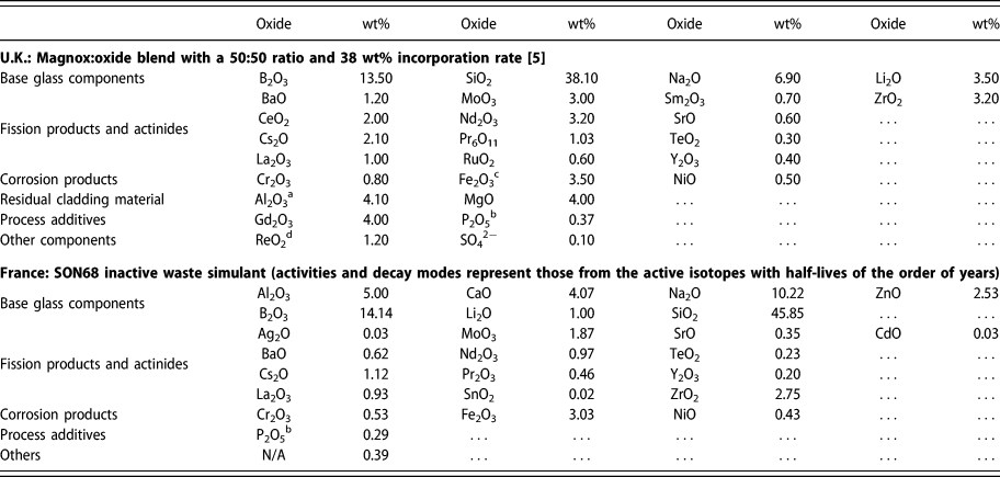
To meet this challenge, an inactive simulant of the glass can be studied. This simulant can include a wide range of inactive isotopes of the fission products or can use a simpler formulation that captures key characteristics [Reference Gin, Abdelouas, Criscenti, Ebert, Ferrand, Geisler, Harrison, Inagaki, Mitsui, Mueller, Marra, Pantano, Pierce, Ryan, Chofield, Steefel and Vienna4]. Compositions of two complex simulant glasses are provided in Table I using data from a U.K. formulation [5] with chemical simulants substituted for certain radionuclides [Reference Taylor, Short, Gribble, Roe and Steele6]. The effect of radiation on this glass can then be explored using a variety of techniques. This includes doping of the glass with a radionuclide [Reference Peuget, Cachia, Jégou, Deschanels, Roudil, Broudic, Delaye and Bart7], utilizing neutron bombardment to initiate a nuclear reaction in boron [Reference Peuget, Fares, Maugeri, Carabello, Charpentier, Martel, Somers, Janssen, Wiss, Rozenblum, Magnin, Deschanels and Jégou8] [capture of the neutron induces alpha emission via the 10B(n,α)7Li reaction] or exposing the glass to external radiation sources, such as an electron beam [Reference DeNatale and Howitt9, Reference Ollier, Rizza, Boizot and Petite10, Reference Mir, Boizot, Charpentier, Gennisson, Odorico, Podor, Jégou, Bouffard and Peuget11], ion beam, or gamma radiation [Reference DeNatale and Howitt12, Reference McGann, Bingham, Hand, Gandy, Kavčič, Žitnic, Bučar, Edge and Hyatt13].
Components of HLW glass simulants.

Note: Actual high level waste contains elements from almost all of the periodic table.
a Found in Magnox fuel cladding.
b From reprocessing.
c Also a fuel additive/impurity.
d A chemical simulant [Reference Taylor, Short, Gribble, Roe and Steele6] of TcO2. Decay modes are for technetium.
One such technique, ion beam experiments, can be used to probe many of the effects of radiation. The ion beam can comprise heavy ions, such as Au, which can be used to create defects in the structure or used to implant decay products, including the recoil nucleus and helium ions. These combined mechanisms make it a useful tool for studying bubble formation. Such experiments also allow for excellent control of dose rates and total dose. A systematic analysis of the use of this technique to investigate bubble formation has yet to appear in literature; a wide variety of ion types, energies, and fluences have been investigated, although there is no single established methodology for these experiments. In this review paper, we summarize the experimental parameters and compare analytical techniques and findings. We also propose further work and consider what that might reveal. We also briefly compare the results with other irradiation techniques.
Nuclear glass structure
HLW originates from the reprocessing of spent nuclear fuel and, as such, the composition depends on the reactor technology and fuel burn-up. Many of the components of the glass form a network structure with oxygen atoms (bridging oxygens) linking other network-forming components (e.g., silicon and boron) together. In general, alkali species, such as lithium and sodium, tend to be randomly distributed throughout the bulk glass [Reference Manara, GranDjean and Neuville14]. These species modify the network, disrupting or weakening it. They can reduce the connectivity of the network; an Si–O bond is broken, resulting in non-bridging oxygens (NBOs). This allows coordination of cations with the NBO, frequently resulting in 5-fold coordination centers and local order. The cations can act as network modifiers or as charge compensators and so affect macroscopic properties, such as viscosity, of the glass [Reference Calas, Cormier, Galoisy and Jollivet15]. For example, when Zn acts as a network former, it bonds to four silica tetrahedra with four Na+ ions acting as charge compensators [Reference Calas, Galoisy, Cormier, Ferlat and Lelong16]. In this way, the cations tend to exist in well-defined sites, determined by the glass composition. Crystalline inclusions can form in a glass that has cooled slowly, a consequence of the self-heating caused by radioactivity. This is most likely where the glass incorporates oxides with a low solubility.
Radiation effects on gas bubble formation
Gas can be generated by irradiation of glass in a variety of ways. Oxygen atoms can be released from the glass network during radiolytic degradation, which can then form molecular oxygen. Alpha decay of various radionuclides results in the ejection of an alpha particle, which, when it slows down to thermal energies, captures electrons and forms helium atoms. An upper limit of helium generation can be calculated directly from the number of alpha decays of the associated radioisotopes, assuming that the helium does not diffuse out of the glass. This, of course, is dependent on the temperature and solubility, the latter property depending on the composition of the glass.
The transport of gaseous species through the glass is determined by solubility (S), which is related to permeability (K) and diffusivity (D). Statistical mechanics has also shown that solubility is related to the availability of interstitial sites within the glass. This “free space” is a consequence of the amorphous glass structure and defects within the structure, such as NBOs. The density of these interstitial sites (N s) as well as the mass of the gas atom (m), the vibrational frequency of the gas atom in its host site (v), and the binding energy of the gas atom in the host site [E(0)] can be related to solubility [Reference Shackelford17]:
 $$S = {K \over D} = {\left( {{{{h^2}} \over {2\pi mkT}}} \right)^{{3 / 2}}}{1 \over {kT}}{N_{\rm{s}}}{\left[ {{{{{\rm{e}}^{{{ - hv} / {2kT}}}}} \over {1 - {{\rm{e}}^{{{ - hv} / {2kT}}}}}}} \right]^3}{{\rm{e}}^{{{ - E\left( 0 \right)} / {RT}}}}\quad ,$$
where h is Plank’s constant, k is Boltzmann’s constant, T is temperature, and R is the ideal gas constant.
The interstitial gas atoms can “jump” between adjacent solubility sites [Reference Shelby18]; hence, gaseous species can be transported through the glass structure. Once the solubility sites are filled, the glass reaches supersaturation, which leads to the possibility of clustering, a precursor to bubble formation. Glass network modifier ions, such as sodium, “compete” with the gas atoms for interstitial sites, effectively reducing the number of sites available to the gas atoms. This can increase the possibility of clustering and subsequent bubble formation [Reference Shackelford17]. If the diffusion of the gas is sufficiently rapid, then the glass may not reach supersaturation and bubbles may not form.
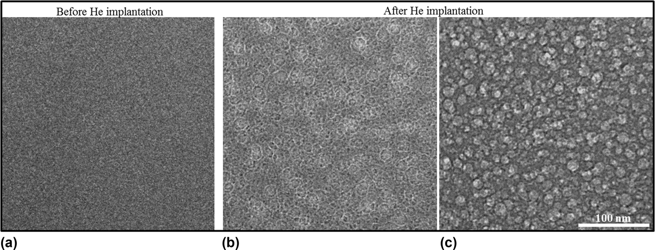
An example of bubbles formed in a U.K. glass formulation, provided by the Microscopes and Ion Accelerators for Materials Investigation (MIAMI) irradiation facility at the University of Huddersfield in the United Kingdom, is shown in Fig. 1 using in situ transmission electron microscopy (TEM) at 143 K after implantation of 8 × 10¹⁶ He/cm2 at 10 keV. Similar in situ studies have previously reported the growth of bubbles as fluence is increased [Reference Gutierrez, Peuget, Hinks, Greaves, Donnelly, Oliviero and Jégou19].
An example of bubbles forming in the U.K. formulation Ca/Zn glass. Due to the availability of literature data on He implantation of the French SON68 nuclear waste glass, the He implantation experiments on the Ca/Zn glass were performed under the same conditions for a direct comparison between these two wasteforms. Thin TEM specimens were prepared using FIB and implanted with 10 keV He at 143 K at the MIAMI irradiation facility at the University of Huddersfield, U.K. As in the SON68 glass, He bubbles were seen in the Ca/Zn glass, with bubbles forming after implantation with 8 × 10¹⁶ He/cm2. Detailed studies looking at the effect of implantation temperature on He bubble precipitation, growth and size distributions are underway. (a) Un-irradiated sample. (b) Overfocused image of the irradiated sample showing Fresnel fringes, confirming the presence of bubbles. (c) Underfocused image of the irradiated sample (defocus 2000 nm). Images are provided by Anamul Haq Mir.

Work using electron beams [Reference Hall, Dalton, Hudson and Marples20] has suggested that electronic effects can lead to the generation of molecular oxygen, which may also reside in bubbles. Current understanding suggests that the main effect of this is sodium ion migration together with a removal of NBOs from the glass structure [Reference Howitt, Chan, DeNatale and Heuer21]. The migration of these sodium ions, which act as network modifiers, results in the formation of molecular oxygen, resulting in a region rich in O2 but depleted in sodium. Recent studies using electron beams to produce a bulk irradiation (i.e., the electrons pass straight through the glass and are not deposited) have shown that electrons stimulate desorption of sodium from the surface of the glass, corresponding to an enrichment of molecular oxygen in this region [Reference Mir, Boizot, Charpentier, Gennisson, Odorico, Podor, Jégou, Bouffard and Peuget11], which could result in the formation of bubbles at the surface. The mixed alkali effect has been seen to reduce ion migration and so inhibit oxygen bubble formation, although this was seen to be composition dependent [Reference Boizot, Ollier, Olivier, Petite, Ghalen and Malchukova22]. In the study on the mixed alkali effect, the presence of molecular oxygen was associated with a change in boron coordination, shifting from BO4 to BO3.
Gamma radiation produces secondary electrons which may also generate the same effects as electron irradiation [Reference DeNatale and Howitt12]. Work on the PNL (Pacific Northwest formulation) glass suggested that the electronic stopping of heavy ions could also produce this effect [Reference DeNatale, Howitt and Arnold23]. This glass was analyzed by TEM and after irradiation with helium, argon, or lead ions. Comparison with a control sample ruled out the effect of the electron beam. Although the composition of these bubbles was not analyzed, the authors suggest that they may contain oxygen, formed by the same mechanism as electron beam irradiation. They also note that for argon and helium, a portion of the composition of these bubbles may be due to the implanted ion. Conversely, other work on a complex glass (GP 98/12) did not show any bubble formation during helium ion irradiation [Reference Evron, Cohen, Regev and Eyal24]. Both small angle X-ray scattering (SAXS) and TEM were used to confirm this.
The most comprehensive description of oxygen bubble formation due to electronic interactions used a 300 keV TEM beam to irradiate a 5-component glass with a range of flux and temperatures [Reference Ollier, Rizza, Boizot and Petite10]. This study found that, for a given temperature, there is a threshold electron flux below which bubbles will not form. Bubbles were observed at temperatures above 100 °C at any flux used in the experiment, suggesting that simultaneous sample heating and irradiation is required to induce oxygen bubble formation as, at higher temperatures, the molecules (oxygen and sodium ions) and vacancies have sufficient energy to diffuse. The flux threshold was explained by considering that, at low flux, annihilation of the precursor defects for alkaline diffusion occurs and so the formation of molecular oxygen is inhibited.
General experimental parameters
To date, a variety of glass compositions have been studied by ion beam irradiation, mainly the French SON68 glass as well as a variety of simple glasses. Irradiation has tended to utilize helium ions to investigate the effect of alpha decay, although gold [Reference Mir, Peuget, Toulemonde, Jégou, Miro and Bouffard25, Reference Karakurt, Abdelouas, Guin, Nivard, Sauvage, Paris and Bardeau26], xenon [Reference Chen, Zhang, Lv, Zhang, Du, Yuan, Nan, Zhu and Wang27], bismuth [Reference Dube, Stennett, Gandy and Hyatt28], and lead [Reference DeNatale, Howitt and Arnold23] have also been used in studies where the formation of molecular oxygen has been observed or postulated. The energy and fluence of the ion beam are important in determining how the ion beam interacts with the glass. It is also noted that when either the sample preparation or the analytical technique involves irradiating the sample with electrons or ions, this can also have an effect on bubble formation [Reference Mir, Boizot, Charpentier, Gennisson, Odorico, Podor, Jégou, Bouffard and Peuget11, Reference Gutierrez, Peuget, Hinks, Greaves, Donnelly, Oliviero and Jégou19]. A summary of the studies available in the literature is provided in Table II.
Summary of the materials, experimental parameters and results from literature where bubble formation from ion irradiation is discussed.

Note: For glass type “simple,” the numbers in parentheses represent the number of components of the glass. “Prep” refers to the preparation of the sample prior to irradiation: B = glass blowing; M = mechanical polishing; P = pre-irradiated, A = annealed, U = ultrasonic cleaning, N/A = preparation technique is not stated but it is assumed that the samples are irradiated as received, N/S = not stated.
a Other irradiations, including pre-irradiation with heavy ions, were also reported but not in relation to bubble formation and hence details are not reported here.
b The samples were milled using FIB after irradiation.
Glass composition and preparation
As noted in “Introduction” section, the composition of HLW glass varies considerably, and such glasses are referred to as complex glasses. Their complexity can make analysis and comparison with other studies challenging, so a variety of simpler compositions exist. Ion beam studies require thin samples no more than a few millimeters in depth, which necessitates careful preparation, although several studies have shown that the preparation method itself may lead to bubble formation. These aspects will be discussed in more detail in the sections ‘simple glass formulation’ and ‘Preparation of glass for ion beam experiments’.
Simple glass formulation
In 2013, it was reported that a 6-component simple glass would be used as a standard for collaborative study, mainly into HLW glass dissolution [Reference Gin, Abdelouas, Criscenti, Ebert, Ferrand, Geisler, Harrison, Inagaki, Mitsui, Mueller, Marra, Pantano, Pierce, Ryan, Chofield, Steefel and Vienna4]. Known as the international simple glass (ISG), it is an aluminoborosilicate, which also contains sodium, calcium, and zirconium oxides. A single batch was made and ingots were distributed for study by the partner nations (United States, France, United Kingdom, Japan, Belgium, and Germany). Other simple glasses exist, for example, commercial borosilicate glass manufactured by CorningInc. (Corning, New York). It is also possible to formulate other compositions to investigate the effect of changing composition.
Complex glass formulation
A variety of inactive models of complex glasses have also been formulated. These utilize an inactive simulant of HLW and comprise stable isotopes of the fission products. Where no stable isotope exists, the amount of available isotopes is either increased pro rata or the active isotope is replaced on a molar basis with a nonactive element with similar properties. Currently, the most widely studied complex glass is the inactive reference glass developed by CEA, referred to as SON68.
In the United Kingdom, a dedicated full-scale processing plant is available to produce inactive simulant glasses [Reference Harrison29]. In this process, HLW simulant is calcined, incorporated into molten base glass, and poured into canisters. Historically, two types of HLW have been produced: Magnox, which originates from the U.K. first-generation power reactors, and oxide, which originates from the Thermal Oxide Reprocessing Plant. The Magnox HLW can be directly incorporated into the glass, whereas the oxide HLW is blended with Magnox HLW before calcination and vitrification. Glass has been produced with a variety of incorporation rates, up to 38 wt% metal oxides [5]. In the near future, the United Kingdom intends to move to a once-through fuel cycle, meaning that reprocessing operations will come to an end. The HLW storage tanks will be washed out prior to decommissioning, and it is likely that this waste will also be vitrified. This waste will have a different composition, and as such, a new base glass composition has been developed. This base glass includes calcium, zinc, and aluminum, in addition to the lithiated sodium borosilicate glass currently in use.
The composition of the glass can affect how the ion beam interacts with the sample, as will be shown below.
Preparation of glass for ion beam experiments
An effective and common method to produce suitably thin samples for ion beam experiments is to use focused ion beam (FIB) milling. This can produce samples less than a micrometer thick. Since the principle of this technique involves a high-energy (tens of keV) ion beam, it is possible that this may generate artifacts, which can lead to bubble nucleation. Indeed, a novel study utilizing in situ TEM showed that bubbles tended to form in linear clusters, and the authors suggested that this pattern “could be due to local stress induced by FIB lamellae preparation” [Reference Gutierrez, Peuget, Hinks, Greaves, Donnelly, Oliviero and Jégou19]. Other studies have utilized a polishing procedure, which involves using a fine (µm) diamond or carbon paste to carefully grind the sample (mounted in a suitable holder). In many of these studies, the sample was then annealed to remove any stresses introduced during mechanical polishing.
Irradiation parameters
The effect of ion energy and mass
The interaction of the ion beam with the target material will cause energy to be transferred to the material and the incident ions to slow down. The rate of this energy loss (E) per unit path length (x) is termed linear stopping power or sometimes linear energy transfer (S):
 $$S = - {{{\rm{d}}E} \over {{\rm{d}}x}}\quad .$$
Linear stopping power is a sum of the electronic stopping power (S e—collision of the ion with electrons) and nuclear stopping power (S n—collision with the nuclei):
 $$S = {S_{\rm{e}}} + {S_{\rm{n}}}\quad .$$
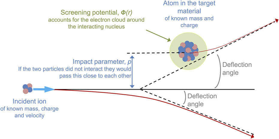
The nuclear stopping power can be calculated by considering the conservation of energy and momentum of the system. Numerical techniques for solving this rely on defining a center-of-mass coordinate system, such that the relative motion of the two particles can be mathematically reduced to that of a single particle moving in a potential energy field. This coordinate system relates the angular momentum to the minimum distance that would exist between the two particles if they passed each other without interacting, using the impact parameter (p). The final mathematical form of the nuclear stopping power accounts for the mass and velocity of the particles (as well as energy transfer and interaction angles), repulsive Coulomb interactions between the nuclei, and screening of the nuclei by the electron cloud, described, for example, by the Ziegler, Biersack, and Littmark (ZBL) potential [Reference Ziegler, Biersack and Littmark30]. This screened interatomic potential depends on the charge state of both particles as well as the distance between the particles. A representation of these interactions is provided in Fig. 2.
Representation of the interactions contributing to nuclear stopping power, and including the initial trajectory of the incident ion, the energy transferred to the atom in the target material and the minimum distance that would exist between the two particles if they did not interact.

The likelihood of the ion interacting with the target atom is found from considering the collision distance, d (also thought of as the distance of closest approach if p = 0), which relates the kinetic energy of the system to the Coulomb energy:
 $${1 \over 2}{M_{\rm{c}}}V_0^2 = {{2{Z_1}{Z_2}{e^2}} \over d}\quad ,$$
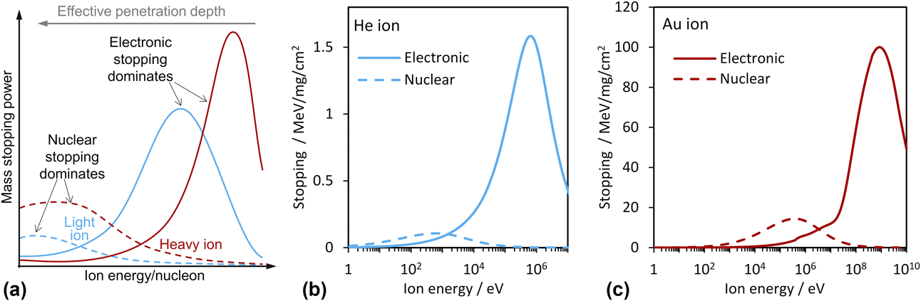
where M c is the mass of the system in center-of-mass coordinates, V 0 is the initial velocity of the projectile, Z 1 and Z 2 are the charges of the particles, and e is the charge on an electron. Rearranging for d suggests that the nuclear stopping power will be greater for a system with lower kinetic energy (and hence an incident ion with lower energy) and will scale with the charge on the incident ion. At sufficiently low energies (typically around the energy of an alpha recoil nucleus), nuclear stopping decreases, as shown in Fig. 3.
(a) Schematic representation of the dependence of nuclear and electronic interactions on ion energy (which relates to penetration depth). For an ion of a given mass, there are two curves, one for each interaction: dashed lines are nuclear stopping power and solid lines are electronic stopping power. (b) Stopping powers for a He ion and (c) a gold ion in borosilicate glass (density 2.58 g/cm3), as calculated by SRIM.

Electronic stopping power can be calculated using, for example, the Bethe formula [Reference Bethe, Ashkin and Segré31], which describes the mean energy loss per distance traveled of swift charged particles (excluding electrons) traversing matter. Historically, the Bethe formula is used for high energies (above the Bragg peak). For low energies, LLS (Lindhard, Scharff, and Schiott) theory has been used [Reference Lindhard, Scharff and Schiott32]. More recently, extensive experimental work has led to advances in this area, such as those incorporated into the PASS code [Reference Sigmund and Schinner33]. Electronic stopping depends on the electron density of the material, and hence on the composition, as well as the velocity of the incident ion and its charge state. At high energies, and hence high velocities, electronic interactions are more dominant than nuclear interactions, and this scales with mass of the incident ion.
Figure 3 shows a schematic of the electronic and nuclear stopping powers for light and heavy ions as a function of energy. Since the ion will lose energy as it passes through a medium, the penetration depth can be thought of as the inverse of the ion energy. A higher energy or a lighter ion will result in an overall greater penetration depth. These trends are summarized in Table III. This means that the energy of the incident ion can be selected to investigate the interaction of choice at a given depth.
Summary of the dominant interactions for a variety of ion energies and masses as well the effect on penetration depth.

Since the composition of the target material is key in defining the interaction of the ion beam, a mass stopping power (S m) can be defined, which accounts for the density (ρ) of the material:
 $${S_{\rm{m}}} = {S \over \rho }\quad .$$
These calculations are used in software, such as SRIM (stopping range of ions in matter) [Reference Ziegler, Biersack and Littmark30], to determine the displacement of atoms within a target material of known composition, for an ion of a given energy, and to calculate the electronic and nuclear energy loss from incident ions and recoils.
Fluence and dose
Fluence is a measure of the number of ions that pass through a given area. Total dose is calculated as the amount of energy deposited per unit mass. There are several ways that this can be determined. One of the simplest uses charge collection dosimetry, which requires that the ions all possess the same charge (ne, defined as the charge state multiplied by the charge on an electron). Here, the beam current (I) is measured and the number of incident ions (N) at a given time (t) can be found using the following equation:
 $$N = {{It} \over {ne}}\quad .$$
The initial energy of the ion beam (E) is defined during accelerator setup. The deposited energy (D E) can then be calculated in units of energy (typically reported in eV):
 $${D_E} = NE\quad .$$
Knowing the area of the sample to be irradiated as well as the penetration depth of the ion beam (d—calculated using the stopping power) means that the irradiated volume can be found and then, in combination with the density (ρ), the total dose can be found in Gy by converting the deposited energy from eV to J (by dividing by the electron charge: 1.6 × 10⁻¹⁹). This can be summarized as follows:
 $${\rm{Dose}} = {{ItE} \over {ne \cdot {\rm{mass}}}} = {{ItE} \over {ne \cdot Ad\rho }}\quad .$$
Since the beam current can vary significantly over time, charge collection dosimetry is the preferred method for measuring the dose to—or damage inflicted on—a sample. For this reason, fluence (ions/cm2) is usually reported.
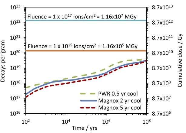
This can be related to real waste using decay calculations; the results [Reference Burns, Hughes, Marples, Neilson and Stoneham34] of which are shown in Fig. 4. In these calculations, the major contributor to α-decay is found to be 241Am, producing an α particle with around 5.4 MeV (the recoil nucleus is 237Np, which has an energy of the order of 100 keV). Assuming that all α-decays produce α particles of a similar energy and that the α particles remain in the glass, then the dose from the α particles can easily be found.
α-decay in vitrified HLW, based on 12.5% incorporation [Reference Burns, Hughes, Marples, Neilson and Stoneham34]. Decays per gram are taken from literature; cumulative dose is calculated from these data for a 5.4 MeV α-particle. The horizontal lines represent the total dose delivered to a glass sample on a beam line, subjected to a given flux, using data from Table IV. Reprinted with permission from Ref. [Reference Burns, Hughes, Marples, Neilson and Stoneham34] (Elsevier, 1982).

The dose from accelerator experiments can be found by irradiating a defined area, using SRIM calculations to determine the penetration depth and using the density (taken as [5] 2.94 ± 0.01 g/cm3 for a 50:50 blend at 38 wt%), comparison can be made, as shown in Table IV. Here, SRIM calculations resulted in a penetration depth of 25.35 μm for a 5.4 MeV α particle. Calculations were carried out using a 38 wt% incorporation rate with a base glass composition as defined in Table I. For simplicity, the composition of the incorporated metal oxides was assumed to be entirely CeO2. (a typical fluence for α particles generated from a linear accelerator, such as the one available at the Dalton Cumbrian Facility [Reference Leay, Bower, Horne, Wady, Baidak, Pottinger, Nancekievill, Smith, Watson, Green, Lennox, Laverne and Pimboltt35], is 1015–1017 ions/cm2 over an area 1 cm2—achieved by irradiating for a given amount of time). Typical beam current of 1 μA can be reliably achieved, although values between 1 nA and 5 μA have been used. The energy supplied from the ion beam would cause dramatic heating of the sample, which can be monitored using a thermal camera and controlled using a cooling loop [Reference Wady, Draude, Shubeta, Smith, Mason, Pimblott and Jimenez-Melero36].
Summary of flux and fluence for a 5.4 MeV α particle and the relation to dose for a similar alpha particle emitted by alpha decay. Each incident ion is equivalent to the release of an α particle from a decay event Dose rates are calculated assuming an irradiated area of 1 cm2, a penetration depth of 25.35 μm, calculated using SRIM, and a density of 2.94 g/cm3. Where the flux is converted to decays/cm2/year, the flux has been multiplied by the number of seconds in a year. Using the density, and penetration depth calculated by SRIM, this is then converted to decays/g/year. The time required to reach a given fluence together with Fig. 4 demonstrates the accelerated dose rate of ion beam experiments compared with actual HLW. The equivalent dose rate provides further underpinning of the difference between experiment and actual conditions.

Temperature and gas diffusivity
The energy imparted to the sample from the ion beam will cause an increase in temperature. This can be controlled using a heat sink, for example, a copper block and a cooling circuit. Temperature is important because it affects the diffusivity of the gas molecules. For gaseous ions, the implanted gas profile is also affected by the potential of the implanted ions to diffuse out of the sample. This will be expanded on in the section “Helium diffusivity”. Heating of the glass can also cause annealing of any defects that may be generated by irradiation. Although this may be happening in the real glass product, control of this phenomenon is important in understanding the behavior of the glass as a whole.
Analytical techniques
Analysis of structural changes of nuclear glasses tends to fall into two categories: imaging via TEM or scanning electron microscopy (SEM) or a combination of integrity tests and other structural probes, usually involving Raman spectroscopy, microhardness indentation, nuclear magnetic resonance (NMR), time-of-flight secondary ion mass spectrometry (ToF-SIMS), and atomic force microscopy (AFM) to measure density changes/swelling. AFM utilizes a very sharp tip of a cantilever to measure the forces applied by intermolecular interactions with atoms within the glass [Reference Arribart and Abriou37]. Scanning the tip across the surface of the sample and measuring the change in force allows a 3-dimensinal map of the surface to be created, allowing measurement of swelling or compaction. It should be noted that since TEM and SEM involve bombarding the sample with electrons, it is possible that they may promote bubble formation. Although most studies include a control sample that has not been irradiated by ions to rule this out, studies [Reference Mir, Peuget, Toulemonde, Jégou, Miro and Bouffard25, Reference Mir, Monnet, Touelmonde, Bouffard, Jégou and Peuget38] have noted that the sequence of irradiation with multiple heavy ions has differing effects on the microstructure of the glass. This suggests that while electron imaging alone may not result in bubble formation, it is possible that heavy ion irradiation followed by electron imaging may.
There are also several more novel techniques, which have only been employed in isolated studies: SAXS was used to determine bubble radius and volume [Reference Terekhov, Heuser, Okuniewski, Averback, Seifert and Jemian39]; nuclear reaction analysis (NRA) has also been used to determine the diffusivity of helium [Reference Chamssedine, Sauvage, Peuget, Fares and Martin40, Reference Fares, Peuget, Chamssedine, Sauvage, Bouty, Broudic, Deschanels, Maugeri, Bès and Jégou41, Reference Bès, Sauvage, Peuget, Haussy, Chamssedine, Oliviero, Fares and Vincent42]. The incident ion undergoes a nuclear reaction with the target atoms, generating ionizing radiation. In this instance, 3He+ is first implanted into the sample and these are the target atoms. A deuterium beam (2H+ or simply, d) is then used to prompt a nuclear reaction with the 3He (now neutral), resulting in the emission of a proton (1H) and an alpha particle (4He2+), usually written as a 3He(d,α)1H reaction schemeFootnote a or more fully as follows:
 $${}_1^2{{\rm{H}}^ + } + {}_2^3{\rm{H}}{{\rm{e}}^ + } \to {}_2^4{\rm{H}}{{\rm{e}}^{2 + }} + {}_1^1{\rm{H}}\quad .$$
The emitted protons and alpha particles can then be detected and their scatter, as well as the energy of the alpha particles, used to pinpoint their origin and hence the location in the sample from which they originated. For a thorough description of experimental setup, the reader is referred to a recent publication by EURATOM [Reference Markelj, Ogorodnikova, Pelicon, Schwarz Selinger, Vavpetič and Čadež43].
Recent work
Since the original development work carried out in the 1980s, a variety of studies have been produced. In particular, a number of papers have been published on the SON68 formulation and a great deal of effort has gone into determining the diffusivity of helium in this glass. In addition, heavy ions have also been used to simulate structural damage and a variety of simple glasses have also been tested. A number of novel studies that make use of multiple irradiations of a single sample have also been carried out to simulate the effect of both the alpha recoil nucleus under the nuclear interaction regime and the alpha particle itself under the electronic interaction regime.
Work on SON68 glass
Helium diffusivity
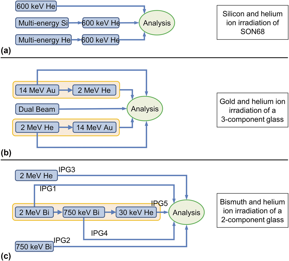
A series of studies using NRA determined the diffusivity of helium in SON68 glass. 3He was implanted at 143 K to prevent any mobility of the ions, and the glass was then annealed at a variety of temperatures. The authors suggested [Reference Chamssedine, Sauvage, Peuget, Fares and Martin40, Reference Fares, Peuget, Chamssedine, Sauvage, Bouty, Broudic, Deschanels, Maugeri, Bès and Jégou41, Reference Bès, Sauvage, Peuget, Haussy, Chamssedine, Oliviero, Fares and Vincent42] that some of it may get trapped in cavities. Initial work [Reference Chamssedine, Sauvage, Peuget, Fares and Martin40] showed that a portion of the helium was not mobile, and it was assumed to be trapped in defect centers created by irradiation or in pores. Further work [Reference Fares, Peuget, Chamssedine, Sauvage, Bouty, Broudic, Deschanels, Maugeri, Bès and Jégou41] included TEM, which did not show any bubbles, cracks, or pores, although the analysis was limited by a resolution of 1 nm and was performed at room temperature. It was suggested that the bubbles may have formed but that there was a purely elastic deformation of the glass network—diffusion of the helium meant that any changes to the microstructure were reversed when it migrated. This study looked at a variety of fluences and damage regimes, although the imaging was only performed on a limited number of samples. The conditions for these imaged samples are reported in Fig. 5(a).
Overview of the schemes involving multiple irradiations of a sample where bubble formation was investigated for at least part of the experiment. In the lower schematic, IPG refers to the notation used in the paper for identifying the samples and only IPG3, IPG4, and IPG5 were analyzed for bubbles. (a) Si and He ion irradiation of SON68 [Reference Fares, Peuget, Chamssedine, Sauvage, Bouty, Broudic, Deschanels, Maugeri, Bès and Jégou41], (b) Au and He ion irradiation of a simple glass [Reference Mir, Peuget, Toulemonde, Jégou, Miro and Bouffard25], and (c) Bi and He ion irradiation of a simple glass [Reference Dube, Stennett, Gandy and Hyatt28].

In a final study [Reference Bès, Sauvage, Peuget, Haussy, Chamssedine, Oliviero, Fares and Vincent42], it was determined that most of the helium implanted is mobile, with only about 20% of the implanted helium demonstrating low diffusivity. In situ TEM suggested that this immobile helium resides in cavities, at most 2 nm in diameter. The authors also noted that helium tended to diffuse toward the surface of the glass, rather than into the bulk, and suggested that the relaxation of irradiation-generated defects in the glass during thermal annealing might be responsible for this.
This work on the French SON68 glass concerning diffusivity has shown that bubbles of helium from ion implantation may not form if the concentration of helium is within the limit of solubility and that once the solubility limit is reached, the helium can migrate away from the area of implantation, taking up solubility sites in unirradiated areas of the glass and hence no bubbles or cracks will be seen [Reference Peuget, Delaye and Jégou44]. They also note that the solubility is affected by the glass composition, in particular by the concentrations of network-modifying elements, which are generally located in the free volume of the glass and so reduce the number of nucleation sites available to gas atoms. This suggests that bubble formation will be affected by temperature, helium concentration, and glass composition. The authors conclude that although nanometer-sized bubbles may form at low temperature, under normal environmental conditions, macroscopic changes or cracking of the glass is unlikely. These studies were limited to a homogeneous glass of a specific composition.
Helium solubility
In a novel study [Reference Gutierrez, Peuget, Hinks, Greaves, Donnelly, Oliviero and Jégou19], helium fluence was increased stepwise with in situ TEM imaging taken at each interval. Here, bubbles of 2 nm in size form after 2.8 × 10¹⁶ He/cm2. This is the lower limit of resolution of the TEM, so it is possible that smaller bubbles were present at a lower fluence. The bubbles then grow in size as the fluence is increased, with a maximum circular bubble radius of 35 nm at the highest fluence of up to 23 × 1016 He/cm2. Elongated bubbles were also seen as two smaller bubbles grew in size and began to coalesce. The bubbles tended to form along lines, and that these may correspond to local stresses induced by the FIB preparation. There is no mention of the composition of these bubbles.
Other studies
Most recently [Reference Karakurt, Abdelouas, Guin, Nivard, Sauvage, Paris and Bardeau26], both SON68 glass and the ISG were irradiated with both 1 MeV He+ and 7 MeV Au5+ at room temperature (water cooled). Raman spectra revealed molecular oxygen in the gold-irradiated glass along with structural modifications that seem to indicate depolymerization. Swelling and a reduction in hardness were also observed. These structural variations were less apparent in the helium-irradiated glass. Imaging of the glasses was not performed, so it is unclear whether this oxygen has coalesced into relatively large bubbles, or whether it exists as dispersed, discrete molecules in the interstitial cavities.
Simple glasses
There are five studies in the literature, which are concerned with bubble formation in simple glasses. Each study has investigated a separate simple glass formulation, provided in Table V.
Compositions of the simple glasses used in ion beam experiments.

a Composition reported as mol%.
In 2006, a 7-component (zinc–titania–borosilicate) glass was subjected to He+ ions [Reference Terekhov, Heuser, Okuniewski, Averback, Seifert and Jemian39]. The temperature rise due to irradiation was reported to be not more than 373 K. The energy was varied between 1 and 2 MeV to provide a uniform implantation over a 1 µm deep zone. The minimum energy corresponded to an implantation depth of about 4.5 µm, which the authors state, was required to prevent helium loss via solid state diffusion at room temperature. SAXS was used as the analytical technique. The lowest fluence used was 9.4 × 10¹³ He/cm2, and bubbles were indeed detected after the SAXS signal was corrected for by comparison with a zero-dose sample. At a fluence of 4.5 × 10¹⁴ He/cm2, the maximum diameter of the bubbles was recorded as 100 Å, which is the upper limit of detection of SAXS. The composition of the bubbles was not determined but was assumed to be helium. The authors suggest that although not detected, larger bubbles were present at higher doses; hence, the size of the bubbles increases with dose.
More recently [Reference Mir, Peuget, Toulemonde, Jégou, Miro and Bouffard25], a 3-oxide glass was irradiated with both helium and gold ions to probe electronic and ballistic effects, respectively. Figure 5(b) provides an overview of the irradiation scheme. The paper does not specifically mention bubble formation, although the Raman spectra presented show a peak at 1550 cm−1 representing molecular oxygen. This peak appears larger in the irradiated glass than in the pristine glass, even for He ion irradiation alone. Several irradiations were performed on previously irradiated glass (either the helium or the gold irradiation was conducted first) as well as a dual beam irradiation. The authors conclude that the order in which the irradiations occur has an effect on the microstructure, with helium ions promoting partial recovery. It is speculated that this is due to local heating as a result of electronic interactions. These results may be particularly important, where bubble formation by other means, such as electron beam (analogous to β-decay), is observed. Although the presence of molecular oxygen does not strictly mean that bubbles are formed, this is the only dual beam study where possible evidence of bubble formation is observed.
In a similar study [Reference Dube, Stennett, Gandy and Hyatt28], a 2-component iron phosphate glass was irradiated with bismuth and 2 MeV helium ions at liquid nitrogen temperature. A series of irradiations on a single sample was also performed in an attempt to simulate the effect of both the alpha recoil nucleus and the alpha particle itself. The irradiation scheme is shown in Fig. 5(c). A further irradiation with low-energy helium ions was also carried out to simulate bubble formation in the pre-damaged glass. The glass was analyzed mainly using infra-red spectroscopy, and this analysis did not extend to the wavelengths where molecular oxygen would be detected. However, irradiation with 2 MeV He+ alone did not have any observable effect on the chemical structure, and it was presumed that the fluence (6.2 × 10¹⁴ He/cm2) was too low. The effect of the bismuth irradiation was unclear as the order of the irradiations (bismuth alone or before or after helium irradiation) seemed to result in either a depolymerization or polymerization, assumed to be due to localized heating. Bombardment of the pre-irradiated glass with 30 keV He+ ions at a fluence of 2 × 10¹⁷ He/cm2 [denoted IPG5 in the paper, and in Fig. 5(c)] resulted in bubble formation on the surface of the glass, of the order of micrometer size. This was found using SEM, although the composition of the bubble is not analyzed but assumed to be purely helium. This assumption is based on the fact that the concentration of the implanted helium is above the solubility limit. Other samples irradiated with 2 MeV He+ ions did not exhibit blistering on the surface of the glass, and it was assumed that the penetration depth was too great for bubble detection using SEM.
As mentioned in the section “Other studies,” the ISG was also irradiated with helium and gold ions at room temperature [Reference Karakurt, Abdelouas, Guin, Nivard, Sauvage, Paris and Bardeau26]. Structural changes were observed, including possible depolymerization, as found using Raman spectroscopy and a molecular oxygen peak was observed for the samples irradiated with gold ions. A clearly defined peak is not obvious for the helium ion–irradiated glass. In addition, powdered glass was irradiated using krypton ions. Analysis of this powder by NMR revealed a partial conversion of BO4 to BO3, which supports trends seen in the Raman spectra for the gold- and helium-irradiated glass. It is postulated that the molecular oxygen results from the depolymerization. The tetrahedral boron requires a charge compensator, whereas the trigonal boron does not. This is a weaker bonding structure, which was evidenced by a decrease in microhardness.
Finally, a 7-component glass was irradiated [Reference Chen, Zhang, Lv, Zhang, Du, Yuan, Nan, Zhu and Wang27] with 5 MeV Xe23+ with fluences between 1013 and 2 × 10¹⁶ ions/cm2. The total penetration depth was calculated to be 1.76 µm with electronic effects dominating over the first 0.9 µm. The temperature was not reported. Molecular oxygen was observed at fluences above 1015 Xe/cm2 using Raman spectroscopy and the migration of Na+ ions toward the surface of the sample was seen using ToF-SIMS. The formation of O2 was ascribed to the electronic effect of the Xe ions interacting with the glass, and comparison with both electron and Au ion irradiation suggested that there is a positive correlation between the degree of the electronic effects and the amount of O2 formed. A threshold value of the electronic energy was noted, which depends on the nature of the incident ion. It was also suggested that nuclear energy deposition can inhibit the formation of O2. The distribution of O2 was studied, and it was suggested that it can migrate to the surface of the sample following alkali channels.
Discussion
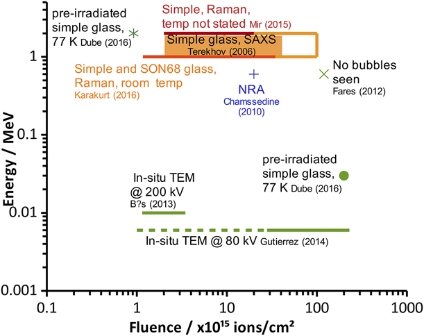
Comparing the results of these studies is not straightforward. Evidence from ion irradiation of metals has shown that dose rate (flux) governs bubble formation [Reference Poon, Macaulany-Newcombe, Davis and Haasz45, Reference Callisti, Karlik and Polcar46]; however, few studies have provided this information or the information required to calculate it. Nevertheless, some conclusions can be drawn. Several studies have suggested that the composition of the glass is key. With this in mind, the largest body of work on a single glass composition relates to SON68. Of the studies that looked for bubbles using imaging techniques after helium ion irradiation, one did not detect bubbles (Fares et al. [Reference Fares, Peuget, Chamssedine, Sauvage, Bouty, Broudic, Deschanels, Maugeri, Bès and Jégou41]) and the two others (Gutierrez et al. [Reference Gutierrez, Peuget, Hinks, Greaves, Donnelly, Oliviero and Jégou19] and Bès et al. [Reference Bès, Sauvage, Peuget, Haussy, Chamssedine, Oliviero, Fares and Vincent42]) did. Where bubbles were not seen, it was assumed that the gas species migrated and the glass structure relaxed prior to analysis; in the studies where bubbles were detected, in situ TEM was used, so that bubbles could be seen as they formed. It would have been instructive to observe these samples for a period after irradiation to determine whether the structure did indeed relax, causing the bubbles to vanish. These experiments were all conducted at a similar temperature (143–159 K) to minimize diffusion but at different ion energies. As Fig. 6 shows, Gutierrez et al. used a range of fluences, which bound the fluences of the other studies, but bubbles were not observed until a fluence of 2 × 10¹⁶ ion/cm2 (at 6 keV) was reached, which should correspond to the solubility sites become filled. In contrast, Bès et al. reported bubble formation at a lower fluence of up to 3.45 × 10¹⁵ ions/cm2 (at 10 keV). In both these studies, samples were prepared for irradiation using FIB. It is possible that electronic effects from the higher energy used by Bès et al. promoted the creation of molecular oxygen, which could contribute to bubble formation, although we also note that the TEM analysis used a much higher voltage (200 kV compared with Gutierrez’s 80 kV). This higher electron beam voltage may have resulted in bubble formation during analysis, rather than bubble formation due to the ion beam.
Comparison of experimental parameters for helium ion irradiation. Analysis was carried out by electron imaging of SON68 glass irradiated at 143–150 K unless otherwise stated. A dashed line represents data where bubbles were not found.

In the only study on SON68 glass to use Raman spectroscopy after helium ion irradiation, molecular oxygen was seen; however, without microscopy, it is not known whether this formed bubbles. This experiment also suggests that in the previous studies, the bubbles that were seen may not have been composed entirely of helium. Analysis using electron energy loss spectroscopy (EELS) may have been useful in pinpointing the location of helium, and comparison with Raman microscopy could indicate whether this was colocated with oxygen. Again, this study was conducted under different conditions to those that used electron imaging: room temperature and an ion energy of 1 MeV, much higher than previous studies. A systematic approach to SON68 glass, in which temperature, helium ion energy, and fluence are considered separately, would be beneficial in determining the exact conditions under which bubbles form in this particular glass composition.
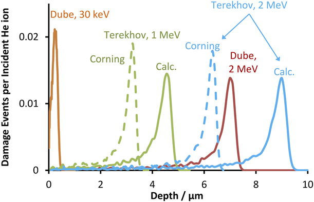
Where simple glasses are investigated, all the studies provide evidence for bubbles or cavities. Out of the five studies, only two used techniques to detect cavities (bubble structures): either SAXS (Terekhov et al. [Reference Terekhov, Heuser, Okuniewski, Averback, Seifert and Jemian39]) or SEM (Dube et al. [Reference Dube, Stennett, Gandy and Hyatt28]). Both these studies use helium ions but at very different energies, 1–2 MeV and 30 keV–2 MeV, as shown in Fig. 6. The fluences used also differ slightly: up to 1 × 10¹⁷ ions/cm2 for one study and 2 × 10¹⁷ ions/cm2 for the other. They also used very different glass compositions. A comparison of penetration depths for these glass compositions and ion energies is provided in Fig. 7. Larger bubbles are expected with a higher fluence since more helium ions are implanted into the glass. The results for 1–2 MeV helium ions found by Terekhov et al. using SAXS suggest that bubbles were present in the 2 MeV study by Dube et al. Neither study stated the density of the glass, although it is known that the glass used by Terekhov et al. (Corning 0211) has a density of 2.53 g/cm3. The results from the study of Terekhov et al. suggested that the manufactured density was used in their calculations [as they state an atomic number density of 7.7 × 10²² atoms/cm3, and the calculated density found by TRIM (TRansport of Ions in Matter, a subset of SRIM that calculated the transport of ions in matter) is 1.68 g/cm3 or 4.85 × 10²² atoms/cm3]. No attempt was made to analyze the composition of the bubbles, and it would be instructive to perform this analysis and determine whether they are purely helium or partially oxygen. Analysis using EELS can determine the helium density [Reference Fréchard, Walls, Koiak, Chevallier, Henry and Gorse47, Reference Prikhodko and Emelyanova48], while Raman microscopy can be used to determine the presence of molecular oxygen [Reference Bowden, Dixon, Gardiner and Carter49, Reference Wang, Guo, Liu, Dai, Wang and Qiu50]. The remainder of the studies of simple glasses use Raman spectroscopy to detect molecular oxygen but, as with other Raman studies, do not state whether the oxygen nucleates into bubbles or is dispersed.
Calculated ion penetration depths from experiments on simple glass where bubble structures (cavities) were reported. For compositions, refer to Table V. All calculations were performed using TRIM (TRansport of Ions in Matter) with a quick calculation method and default values except for those marked “Corning,” which used the density of the glass as supplied by the manufacturer. “Calc.” refers to the density calculated by SRIM and highlights the effect of density on calculated penetration depth. The results from the work of Terekhov et al. using SAXS suggest that bubbles may have been present in the 2 MeV study by Dube et al., but given the penetration depth, may have been below the glass surface and so not accessible to the analytical technique used (SEM).

It is notable that the majority of these studies produced evidence of either bubble formation or gas formation. Each of these studies was carried out under varying conditions though. In addition, although all these studies are on simple glasses, no two studies use the same glass formulation. It was noted by Ollier et al. [Reference Ollier, Champagnon, Boizot, Guyot, Panczer and Padlyak51] that β-radiation effects, such as Na+ migration, densification, and extent of depolymerization depend on composition of the glass. This argument can be extended to electronic effects from heavy ion irradiation. Similarly, Cheng et al. [Reference Cheng, Yang, Zhao, Peng, Skibsted and Yue52] have demonstrated that the addition of CeO2 can inhibit conversion of BO4 to BO3 under irradiation, suggesting that it may have an effect on the mechanism of molecular oxygen formation. Based on this review, it may be more instructive to state that bubbles may form as a result of irradiation for any glass composition, given a sufficient irradiation regime. However, determining whether bubbles will form in HLW glasses required careful consideration, as this review has highlighted synergistic effects between temperature, fluence, glass composition, and irradiation types. Dose rates used in ion beam and electron irradiation studies are often much higher than those found in HLW glass and so the formation of molecular oxygen, which studies have shown requires a dose rate threshold [Reference Ollier, Rizza, Boizot and Petite10], could be considered to be unlikely. However, one limitation of these electron irradiation studies is that they have been carried out on a limited range of compositions, and therefore, the results may not apply to all HLW glass compositions. In addition, where the bulk irradiation due to gamma emission is also considered, the effects of ion migration leading to molecular oxygen formation may not be applicable. Further study is required to understand these synergistic effects.
Attempts to simulate alpha decay by either multibeam or dual-beam experiments have provided ambiguous results, in part because they have used differing experimental conditions, including glass composition, temperature, ion energy, and type of analysis. Analysis of a simple glass composition using SEM (Dube et al. [Reference Dube, Stennett, Gandy and Hyatt28]) indicated bubble formation, but the same result has not been explicitly seen in other work: SEM analysis of SON68 glass (Fares et al. [Reference Fares, Peuget, Chamssedine, Sauvage, Bouty, Broudic, Deschanels, Maugeri, Bès and Jégou41]) did not reveal bubble formation, and work on a 3-component glass (Mir et al. [Reference Mir, Peuget, Toulemonde, Jégou, Miro and Bouffard25]) using Raman spectroscopy found no direct evidence for formation of molecular oxygen. This latter study provided a rigorous approach to determining the effect of the irradiation scheme on the chemical structure of the glass and may have important implications regarding whether bubble formation occurs under any irradiation regime or whether the regime itself can prevent it. Most recently, a combined electron beam and heavy ion study found that, where molecular oxygen was observed after electron irradiation, subsequent irradiation with Xe ions caused the O2 Raman signal to disappear [Reference Mir, Monnet, Boizot, Jegou and Peuget53]. It was not determined whether this molecular oxygen coalesced in to bubbles.
Finally, since many electron beam studies have also resulted in bubble formation [Reference Mir, Boizot, Charpentier, Gennisson, Odorico, Podor, Jégou, Bouffard and Peuget11, Reference Hall, Dalton, Hudson and Marples20, Reference Howitt, Chan, DeNatale and Heuer21], it is possible that the analysis itself, rather than the ion beam irradiation, may promote bubble formation by the formation of molecular oxygen. The ion irradiation may simply mean that bubble formation during electron beam imaging is more likely to lead to bubble formation; thus, the electron imaging of a sample that has not been subject to an ion beam may not be sufficient to rule out post-ion irradiation effects. Recent experiments with electron beam irradiation (Mir et al. [Reference Mir, Peuget, Toulemonde, Jégou, Miro and Bouffard25]) have also suggested the bubble formation is restricted to the glass surface and is related to ion migration. This phenomenon has also been reported as a result of electronic effects in ion beam studies using xenon (Chen et al. [Reference Chen, Zhang, Lv, Zhang, Du, Yuan, Nan, Zhu and Wang27]). This suggests that a variety of complementary analytical techniques should be used to characterize a sample and has implications for bubble formation in authentic vitrified waste, where a number of irradiation fields are present.
Although insight can be gained from conducting studies at temperatures below those at which helium can diffuse, consideration should be given to whether bubbles will form at realistic waste temperatures throughout the lifetime of the waste. The transmutation of radionuclides during their decay chain should also be investigated, as this may have important effects on the chemistry and therefore the chemical structure of the glass [Reference Rose, Woodward, Ojovan, Hyatt and Lee54]. It is particularly important to understand whether bubble formation under these conditions stresses the glass sufficiently to result in widespread cracking. This would increase the surface area for leaching.
Summary
Ion bombardment is a useful tool for determining the effect of both the recoil nucleus and alpha particle itself on the potential for gaseous bubbles to form in nuclear glasses. The studies summarized in this paper show that the nature of bubble formation due to alpha decay is complex and affected by the composition of the glass, the accumulated dose, and the temperature during irradiation. Bubbles as large as micrometers in size have been reported. For these bubbles to form, solubility sites must be filled, indicating that there is a minimum helium concentration required to produce bubbles. This has been observed at temperatures below 150 K and, given that the temperature of vitrified HLW can be much higher than this, it seems that helium bubbles are unlikely to form as the molecules become mobile and can escape the glass. Far less is known about oxygen bubble formation and, where bubbles have been observed, it is possible that some component of these bubbles may be molecular oxygen, most likely formed during depolymerization of the glass network. Electron beam studies suggest that this oxygen can coalesce as a result of a local electric field, causing migration of free ions, and also suggest that this oxygen can be liberated as a result of electronic effects. However, the exact circumstances for oxygen bubbles to form remain unclear and so this phenomenon could be seen in actual nuclear glasses.
Throughout this review, a number of themes have emerged. The irradiation scheme itself is important in eliciting bubble formation and an in-depth understanding of this phenomenon would require a careful, systematic approach using a combination of single-, multi-, and dual-beam experiments. The analytical approach must involve complementary techniques to determine the nature of the bubbles, in particular whether they contain both helium and oxygen and there needs to be better understanding of the extent to which analysis itself may promote bubble formation. Determining whether bubble formation results in stress fractures in the glass would also be useful to underpin a disposability assessment of this wasteform.
Acknowledgments
We thank Anamul Haq Mir for providing the image of bubbles in a U.K. Ca/Zn glass formulation as well as Bill Weber for some useful discussion. We also acknowledge the support of the University of Manchester’s Dalton Cumbrian Facility (DCF), a partner in the National Nuclear User Facility, the EP SRC U.K. National Ion Beam Centre and the Henry Royce Institute. We recognize Paul Wady and Samir Shubeta for their assistance during this review.