I. INTRODUCTION
Ceramic foams combine high chemical and thermal stability with low thermal conductivity and high surface area. Therefore they are ideal candidates for applications in the field of high-temperature insulation, and as catalyst carriers or filters for molten metals.Reference Pyzik, Ziebarth, Han and Yang1,Reference Blome2 In porous ceramics, the size and size distribution as well as interconnectivity and texture of the pores play an important role as they determine properties such as mechanical strength, thermal conductivity and permeability for gases and liquids. The microstructure of porous ceramics is controlled by their processing route and their appropriate parameters.Reference Studart, Gonzenbach, Tervoort and Gauckler3 Many processing routes to porous ceramics exist; most of them can be grouped in either one of the following methods: In the replica method, a polymeric sponge is impregnated with a ceramic suspension and after organic burnout, an open cell foam is obtained where the cell size is determined by the structure of template foam.Reference Schwartzwalder and Somers4 In the fugitive phase method, a sacrificial pore former is used that often results in foams with highly ordered pore structures after removal of the pore former.Reference Schlichting, Padture and Klemens5 In direct foaming, a gaseous phase is dispersed and stabilized in a liquid and both open and closed cell structures can be obtained after drying and sintering, depending on various processing parameters.Reference Gonzenbach, Studart, Tervoort and Gauckler6 Common to all methods, the introduced porosity will affect and alter the mechanical properties of the materials in one way or the other. As a result of this change in mechanical behavior, some mechanical measurement techniques commonly applied for dense ceramics might not be equally suitable for porous ceramics.
The influence of the porosity on the mechanical strength has been studied in detail and Gibson and AshbyReference Gibson and Ashby7 have presented a model to describe this influence. In their “beams and bars” model they describe the connection between porosity and various mechanical properties of cellular ceramics with open and closed-cell structures. According to this model, no influence of cell size is to be expected. Whereas Dam et al.Reference Dam, Brezny and Green8 observed an increase in mechanical strength with increasing cell size in their study on alumina mullite, Brezny and GreenReference Brezny and Green9 showed that this effect was not present in reticulated vitreous carbon and concluded that the change in mechanical strength of the alumina mullite material was rather due to a change in strut microstructure and critical flaw size than cell size effects.
A wide variety of mechanical testing methods can be used to measure the behavior of a material under different stresses. The American Society for Testing and Materials (ASTM) provides standards for the investigation of mechanical properties such as flexural strength (ASTM C116110 and ASTM C167411), compressive strength (ASTM C142412) or hardness (ASTM C132613 and ASTM C132714) of ceramics. Biaxial testing methods such as ball on three balls,Reference Borger, Supancic and Danzer15,Reference Danzer, Supancic and Harrer16 ring-on-ringReference Fessler and Fricker17,Reference Fessler and Fricker18 and Brazilian discReference Fessler and Fricker18,Reference Rasch and Kollenberg19 tests are also well-described in literature and often chosen because of the large tested sample area and the simple and low-cost specimen preparation. However, these testing methods have not been designed specifically for highly porous ceramics with a three-dimensional pore architecture and the behavior of these materials under different loading conditions has not been studied in great detail. Special attention has to be given to pores and their size. As pores at the interface to the testing apparatus reduce the contact area, the stresses are concentrated in the foam lamellae. In addition, pores at the surface of the sample can serve as crack initiation points.
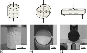
In this study, we investigate the response of porous alumina to 3-point bending, compression and indirect tension using the Brazilian disc method. These methods were chosen due to simplicity in specimen preparation and easy measurement setups and represent a variety of different loading modes. A representative image of the test specimens and the measurement setups is shown in Fig. 1. In addition, schematic drawings of the stresses that are caused by loading of the samples are shown below the measurement setups. In compression testing, a cylindrical sample is loaded axially resulting in compressive forces equally distributed throughout the sample volume. In the Brazilian disc method, a cylindrical sample is compressed in a radial direction resulting in a combination of compressive and tensile forces in a large volume inside the sample. In general, this method offers the advantage of reduced importance of the sample surface finish and therefore potentially better reproducibility as compared with other methods. In 3-point bending, a rectangular sample is placed on two supports and loaded from the top with a third support in the middle, leading to tensile forces at the bottom and compressive forces at the top of the sample. Although 4-point bending is often preferred to 3-point bending due to a larger region of highest stress in the test specimen, this advantage is assumed to be inapplicable to the context of testing herein, as a result of the high defect concentration on the foam surface.
The three different mechanical testing methods used in this study: (a) compressive testing (b) Brazilian disc testing (c) 3-point bending test. A schematic drawing of the stresses involved in the testing methods is shown above the image of the measurement setup.

In this study, we evaluate different mechanical testing methods on their suitability and informative value for the comparison of porous ceramics.Reference Studart, Gonzenbach, Tervoort and Gauckler3 The test material used herein was produced by direct foaming of highly concentrated alumina suspensions. As described in the work of Gonzenbach et al.,Reference Gonzenbach, Studart, Tervoort and Gauckler20,Reference Gonzenbach, Studart, Tervoort and Gauckler21 the introduced air is stabilized by in situ-hydrophobized and surface-active alumina particles, leading to foams with remarkable stability in the wet state which are then processed into porous ceramics.Reference Gonzenbach, Studart, Tervoort and Gauckler6,Reference Gonzenbach, Studart, Steinlin, Tervoort and Gauckler22
II. EXPERIMENTAL
A. Materials
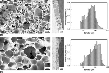
Dried green foams with densities of 0.14 and 0.24 g/cm3 were kindly provided by de Cavis Ltd., Zürich, Switzerland, and are made of high purity α-Al2O3 (>99% purity). Their fabrication route is based on direct foaming of partially hydrophobized alumina particles (Almatis, CT3000 SG, Batch 0927238063, d50 ∼ 500 nm, SSA 8.15 m2/g) to create particle-stabilized foams, as described elsewhere in detail.Reference Gonzenbach, Studart, Tervoort and Gauckler21–Reference Gonzenbach, Studart, Tervoort and Gauckler23 The green foams were sintered in air by heating at a constant rate of 1 °C/min to 1575 °C with a dwell time of 2 h and cooled to room temperature at a constant rate of 3 °C/min. The sintered densities were measured to be 0.216 and 0.360 g/cm3 (94.6 and 90.9% porosity). The average pore size was found to be 39.7 µm for the foam with 90.9% porosity and 84.9 µm for the foam with 94.6% porosity. Exemplary scanning electron microscopy (SEM) images of the pores, the foam lamellae as well as the pore size distributions of both foams are shown in Fig. 2. The determination of the pore size was performed using a semiautomatic image analysis routine described elsewhere.Reference Seeber, Gonzenbach, Ebneter and Gauckler24
Exemplary SEM images of the microstructure and a close up of a foam lamella as well as the pore size distributions of the foams with (a) 90.9% porosity and (b) 94.6% porosity.

For the cyclic loading tests, foam samples with a sintered density of 0.408 g/cm3 (89.7% porosity) were used.
B. Evaluation of three different mechanical testing methods
For the evaluation of the three different mechanical testing methods, samples of different shapes and dimensions are required. For the compression testing, plates of 20 mm thickness were prepared with a Struers Discotom-6 diamond saw and cylinders of 15-mm diameter were cut out using a diamond hollow-core drill. For cyclic compression testing, a larger sample size with a diameter of 2.54 mm and a height of 35 mm was chosen to increase the loaded surface of the specimen and thereby reduce the influence of spallation, as well as to enhance the strain-resolution of the measurement. The samples for the Brazilian disc testing were obtained from plates of 10 mm thickness and were carved out using a 1″ diamond hollow core drill. For the 3-point bending tests, rods of 10 × 10 × 80 mm3 were cut using a diamond saw. As all cutting and drilling was performed in water, the samples were thoroughly rinsed with water after machining and dried for at least 2 days in a 60 °C drying chamber.
All measurements were performed using an Instron 8562 and Bluehill software. The loads were recorded with a 1 kN measurement piezoelectric load cell except for the cyclic loading tests where a 10 kN measurement cell was necessary due to the increased sample size. In the case of 3-point bending, the support span was 60 mm, the load and support bearing diameter was 25 mm and the deflection was measured with an additional sensor between the two supports as can be seen in Fig. 1(c) at the bottom. The large bearing diameter in respect to the sample size was chosen to reduce point load concentrations that lead to localized crushing. All measurements were carried out at a crosshead speed of 0.5 mm/min except for cyclic loading where a crosshead speed of 0.1 mm/min was chosen for better resolution. At least 11 samples were measured for each of the three methods and each of the two foams.
Stresses and strains for the different testing methods were calculated directly inside the Bluehill software as follows:
3-point bending:
 $${\rm{stress \,(MPa)}} = \,\,\,{\rm{load }}\,(N) \times 1.5 \times {{{\rm{support \,\,span \,(mm)}}} \over {{\rm{width \,(mm)}} \times {\rm{thickness}}^{\rm{2}} \,{\rm{(mm}}^{\rm{2}} {\rm{)}}}}\quad,$$
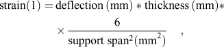 $${\rm{strain(1)}} = \,{\rm{deflection\,(mm)*thickness\,(mm)*}}{{\rm{6}} \over {{\rm{support}}\;{\rm{span}}^{\rm{2}} {\rm{(mm}}^{\rm{2}} {\rm{)}}}}\quad,$$
quasistatic compression:
 $${\rm{stress(MPa)}} = {{{\rm{load}}(N)} \over {{\rm{cross - sectional}}\;{\rm{area(mm}}^{\rm{2}} {\rm{)}}}}\quad,$$
 $${\rm{strain(1)}} = {{{\rm{crosshead}}\;{\rm{displacement(mm)}}} \over {{\rm{thickness(mm)}}}}\quad.$$
Brazilian disc test:
 $${\rm{stress(MPa)}} = {{{\rm{2^*load(N)}}} \over {{\rm{\pi ^*thickness(mm)^*diameter(mm)}}}}\quad,$$
 $${\rm{strain(1)}} = {{{\rm{crosshead}}\;{\rm{displacement(mm)}}} \over {{\rm{diameter(mm)}}}}\quad.$$
III. RESULTS AND DISCUSSION
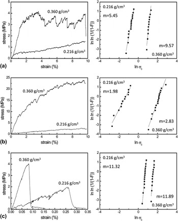
Figure 3 shows representative stress-strain curves of the three different testing methods performed on foams with two different densities as well as the associated Weibull distributions. All results are summarized in Table I.
Stress-strain curves of three different mechanical testing methods and the corresponding Weibull distribution plots. Static compression (a), Brazilian disc testing (b) and 3-point bending (c).

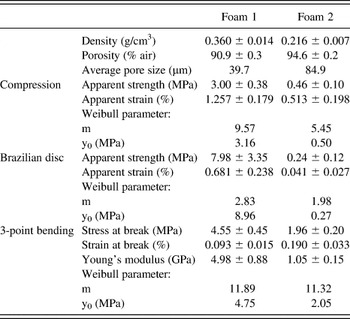
Results of the three different mechanical testing methods performed on two foams with different porosities.

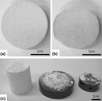
The stress-strain curves demonstrate highly interesting differences between compression or Brazilian disc test on the one hand and 3-point bending on the other. For all test methods, a regime exists where the stress increases linearly with increasing strain. In the course of this quasielastic region, single strut fracture already occurs, typically at the contact area of the sample fixation. This is common for porous ceramics and has already been observed in literature for open cell foams.Reference Dam, Brezny and Green8After reaching the yield strength, one would expect catastrophic failure due to a macroscopic crack propagating through the sample’s cross section with an associated sudden stress drop in the stress-strain curve.Reference Dam, Brezny and Green8 Indeed, this occurs in 3-point bending [Fig. 3(c)], however, interestingly enough this is not observed in static compression or in Brazilian disc testing [Figs. 3(a) and 3(b)]. During both of these latter test methods the stress on the sample increases further after the first struts are broken even though at a reduced rate. It is important to note that all these samples were intact and maintained their mechanical integrity after passing the apparent yield strength. Such a behavior has already been reported by Colombo et al.Reference Colombo, Arcaro, Francesconi, Pavarin, Rondini and Debei25 who compared the mechanical properties of macrocellular and microcellular silicon oxycarbide (SiOC) (with pore sizes below 30 µm). They found that microcellular SiOC exhibits no macroscopic crack propagation after reaching the yield stress and crushes only gradually, as compared with its macrocellular counterpart, which suddenly develops macroscopic cracks. As a result, this significantly different material behavior under compression was attributed to the difference in cell size only. However, in the case of our highly porous alumina foams, we observe a similar stress-strain curve at cell sizes clearly in the regime of macrocellular materials. Furthermore, the strain of up to 1.2% at the apparent yield strength is one to two orders of magnitude higher than typically observed for porous ceramics. This might be due to the high porosity and the very thin struts (typically around 1–2 µm, see Fig. 2) and therefore cracks are not able to propagate through the material but fracture locally after buckling. After reaching the yield stress, this single strut fracturing becomes more pronounced, leading to spalling of small debris wherever parts of the porous structure are destroyed. These spallations are expressed by sudden reduction events in the stress-strain curves. Figures 4(a) and 4(b) show a sample prior to the Brazilian disc test and after being strained to 10%. The deformation due to spalling is clearly visible as the initially circular shape is deformed to a more elliptical shape, where the top and bottom of the sample have adjusted their curvature to the sample holder. This local but with increasing stress continuously occurring material degradation leads to a steady increase of the contact area between the sample and the sample holders resulting in a steady increase of load-bearing capacity of the sample even after reaching the yield strength. This causes an overestimation of the material strength, as the increase in contact area is not taken into account when calculating the stresses of the samples. This effect is more pronounced with samples of higher densities as a slight increase in contact area leads to a much higher areal density of load-bearing struts than with samples of lower densities. In Fig. 4(c), a compression test sample is shown together with the sample holders to further illustrate the building up of debris at the contact area and around the sample during testing. Whereas only in the Brazilian disc test an increase in contact area due to shape deformation is observed, densification at the contact areas can be seen in both testing methods.
Images of a sample before (a) and after (b) the Brazilian disc test. The shape is changed only by material degradation and not by compression of the entire structure. The material degradation can also be observed during compressive testing (c) and leads to accumulation of spalled foam pieces on the sample holders.

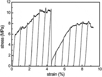
As spallation mainly occurs close to the contact area of the sample holders, we subjected a sample to cyclic compression for investigating the influence of sample degradation on the integrity of the entire structure. Figure 5 shows the stress-strain curve of the cyclic test, where the sample was stressed until 1% strain was reached and then the stress was relieved, allowing the foam to recover some of its elastic deformation. Following the unloading of the sample, the strain was reset and the sample was stressed again up to 1% strain. This loading-unloading cycle was performed 13 times.
Stress-strain curve of a compression test with cyclic loading.

As shown in Fig. 5 thirteen loading-and-unloading cycles lead to a total of 9.28% deformation. This is substantially less than the applied 13% and indicates that the foam is able to deform elastically to a certain extent. This elastic deformation has become possible due to the very thin foam lamellae (Fig. 2), which buckle under load. Although a flatter slope is observed during the first load cycle (Young’s modulus = 1.47 GPa), all following cycles show the same slope independent of the strain that the sample had previously been exposed to (Young′s modulus = 2.26 ± 0.30 GPa). However, the apparent yield stress increases steadily due to densification at the contact area between the sample and the sample holders. The increase of the true contact area due to the densification leads to a more homogeneous distribution of the stresses into the sample. Even after cracking of the sample at 4.5% strain which resulted in a sharp stress drop in the stress-strain curve, a steady recovery of the material strength is observed throughout the following loading cycles. The structural integrity as well as the slope of the stress-strain curves is not affected by the crack in the sample. This example clearly illustrates the remarkable crack tolerance of these foams.
In contrast to compression and Brazilian disc tests, all samples tested under 3-point bending fractured catastrophically after reaching their yield stress [Fig. 3(c)] due to tensile stresses on the struts in the bottom half of the test bars. Similar to as in the cases of compression and Brazilian disc testing, some crushing is observed at the contact area, especially at higher porosity. This is made evident by slight reductions in load during the loading phase as seen in Fig. 3(c). However, crushing of the foam was not sufficient enough to lead to a significant increase of contact area as no indentation was observed on the samples. Therefore the influence on the measured results was assumed to be negligible and the very good reproducibility of the results supports this assumption. Even in 3-point bend tests the average strain at break is exceptionally high with more than 0.1% as compared with dense ceramics, which normally break at 0.01–0.02% strain.
TABLE I shows all results of the mechanical tests for the two foams with different porosities. As expected according to the model of Gibson and Ashby,Reference Gibson and Ashby7 the foams with higher density show better mechanical properties than the foams with lower density. However, the drop in mechanical strength is disproportionately greater than what is to be expected solely from increasing the porosity. Therefore, an influence of the cell size or the strut thickness is probable similar to what has been reported by Brezny and Green.Reference Brezny and Green9 This decrease in strength is observed in all three testing methods. The strains-at-failure in bending are approximately one order of magnitude lower than the strains at which the apparent yield strength is observed in compression and Brazilian disc testing, but still about one order of magnitude higher than that found in dense ceramics of the same composition and grain size. The results obtained in 3-point bending exhibit a low scatter as is made evident by the high Weibull modulus. Whereas the foams still exhibit fairly good Weibull moduli in compression, the scatter observed in the Brazilian disc method is unexpectedly high. The latter is a consequence of the local material degradation at the contact area between the sample and the sample holders resulting in less reproducible load contacts, as spallation of small foam pieces can lead to either material loss outside the sample or densification inside the sample. This effect is more pronounced in Brazilian disc testing than in compression testing, as the initial contact area in the Brazilian disc test is much smaller. In addition, the stresses occurring during Brazilian disc testing should be highest inside the sample [Fig. 1(b)]. However, in the case of our foams, the stresses lead to material degradation at the contact area as shown in Fig. 4(b). As a result, the assumed benefit of low scattering in case of the Brazilian disc test has not accrued to highly porous ceramic samples.
Due to the clear fracturing of the samples in 3-point bending, this method allows best the accurate evaluation of the stress-at-break and therefore the material strength, whereas in compression and Brazilian disc testing no catastrophic fracture occurs. Therefore the evaluation of the apparent yield stress is difficult to be performed reliably as breaking of some struts always occurs even during the initial linear stress increase and thus the determination of the yield stress is not always unambiguous. Therefore, the 3-point bending test is the most suitable method of the three tested ones to compare the mechanical strength of foams with different compositions, microstructures and porosities. However, for understanding the influence of compositional as well as structural properties on the foam strength, further investigations need to be performed with a material where these parameters can be altered independently.
IV. CONCLUSIONS
In this work, we have evaluated three mechanical testing methods on their suitability to compare the mechanical strength of highly porous ceramics. Brazilian disc and compression testing do not lead to critical macroscopic crack propagation even at strains as high as 10%. Only local material degradation is observed at the contact area. In 3-point bending however, catastrophic specimen failure is observed unambiguously and therefore it seems to be the most suitable method to determine the strength at break. Consequently, the mechanical strength of highly porous ceramic foams of varying compositions, porosities and microstructures can be compared. This has been shown on the example of two foams with different porosities. Whereas the mechanical strength decreases with increasing porosity, the deformation tolerance is enhanced leading to a higher strain at break in the more porous material.
ACKNOWLEDGMENTS
The authors would like to thank Mario Mücklich for his help with the sample preparation, Peter Kocher and Linus Ender for their help with the mechanical measurements as well as the Commission for Technology and Innovation CTI, Switzerland, for the financial contribution.