
Introduction
Microcantilever sensors have been increasingly used in biomedical microelectromechanical systems (bioMEMS) devices to measure small scale mechanical movement and are typically silicon-based cantilevers due to availability and easy integration with silicon-based technology.[Reference Fritz1] One application of these microcantilever sensors is in the determination of contractile force of cardiac and skeletal muscle tissues using in vitro body-on-a-chip systems.[Reference Oleaga, Bernabini, Smith, Srinivasan, Jackson, McLamb, Platt, Bridges, Cai, Santhanam, Berry, Najjar, Akanda, Guo, Martin, Ekman, Esch, Langer, Ouedraogo, Cotovio, Breton, Shuler and Hickman2–Reference Wilson, Molnar and Hickman7] These body-on-a-chip systems integrate biology and engineering to measure the biochemical, mechanical, and physiological responses of organ analogues to predict human response to drug and chemical exposure.[Reference Oleaga, Bernabini, Smith, Srinivasan, Jackson, McLamb, Platt, Bridges, Cai, Santhanam, Berry, Najjar, Akanda, Guo, Martin, Ekman, Esch, Langer, Ouedraogo, Cotovio, Breton, Shuler and Hickman2,Reference Stancescu, Molnar, McAleer, McLamb, Long, Oleaga, Prot and Hickman3,Reference Esch, Smith, Prot, Oleaga, Hickman and Shuler8,Reference Sung, Srinivasan, Esch, McLamb, Bernabini, Shuler and Hickman9] The existing microcantilever sensors in body-on-a-chip systems utilize imaging methods or optical laser deflection of cantilevers for calculating contractility[Reference Fritz1,Reference Stancescu, Molnar, McAleer, McLamb, Long, Oleaga, Prot and Hickman3] and rely on imaging methods or expensive optical detection components.[Reference Lee, Hwang, Park, Yoon, Yoon and Kim10,Reference Isarakorn, Linder, Briand and De Rooij11] Since piezoelectric materials have high sensitivity and the ability to convert mechanical energy to an electrical signal, they have been used in a variety of microscale sensor systems, such as pressure sensors and chemical sensors,[Reference Mohammadi, Mohammadi, Barghi and Farzad Ebrahami12–Reference Sangeetha and Juliet14] and as biosensors to detect biological targets such as microbes, proteins, viruses, and nucleic acids.[Reference Johnson and Mutharasan15] Additionally, the ability of piezoelectric materials to convert electrical signals to mechanical energy has led to their use as microactuators.[Reference Tadigadapa and Mateti16] However, these biosensor methods are based on shifts in the resonance frequencies to measure changes in mass on the surface and are not suited for measuring dynamic force changes. Extending the use of piezoelectric materials to cantilever-based muscle contraction bioMEMS devices would enable a direct electrical readout of muscle contraction. Moreover, these cantilevers could also be used in reverse as actuators to impose a stress on tissues attached to the device, specifically the sensory portion of the reflex arc. The stretch reflex arc refers to how the central nervous system senses and responds to peripheral stimuli to regulate skeletal movement and is composed of skeletal muscle, the muscle spindle, motoneurons, and sensory neurons. The sensory portion is composed of intrafusal fibers embedded in the muscle tissue of the muscle spindle and proprioceptive sensory neurons.[Reference Das, Gregory, Molnar, Riedel, Wilson and Hickman17–Reference Rumsey, Das, Bhalkikar, Stancescu and Hickman19] Development of an in vitro sensory circuit of the reflex arc would improve the overall understanding of the mechanosensitive feedback, allowing opportunities to create more physiologically relevant systems and for investigation of neuromuscular diseases.
This present study details the design and fabrication of a piezoelectric bioMEMS cantilever which can act as either a sensing element for muscle contraction or as an actuator to apply mechanical force to cells. This device incorporates a piezoelectric element composed of a thin film of aluminum nitride (AlN) on top of the cantilever sandwiched between two platinum electrodes. As a sensor, bending of the piezoelectric cantilever caused by contracting iPSC-derived cardiac muscle grown on the cantilever surface produced a voltage across the piezoelectric element, which was measured by an external amplifier. As an actuator, a periodic voltage was applied to the piezoelectric cantilevers, and the resultant bending was measured using an optical beam displacement method. This bioMEMS system has the advantage of being able to acquire a direct electrical signal from the cantilever with simple system setup for high content systems and may offer the advantage of high-throughput data collection by integration with current robotic screening systems in drug discovery. While other studies have shown either detection[Reference Barkam, Saraf and Seal20,Reference Chorsi, Curry, Chorsi, Das, Baroody, Purohit, Ilies and Nguyen21] or actuation[Reference Chorsi, Curry, Chorsi, Das, Baroody, Purohit, Ilies and Nguyen21–Reference Mota, Labardi, Trombi, Astolfi, D'Acunto, Puppi, Gallone, Chiellini, Berrettini, Bruschini and Danti23] of cultured cells using piezoelectric bioMEMS devices, we demonstrate a single device capable of performing both functions.
Experimental details
Design and fabrication of piezoelectric cantilevers
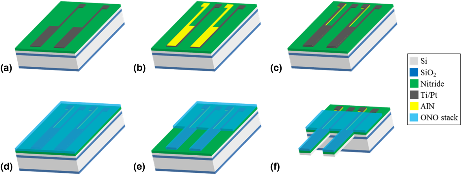
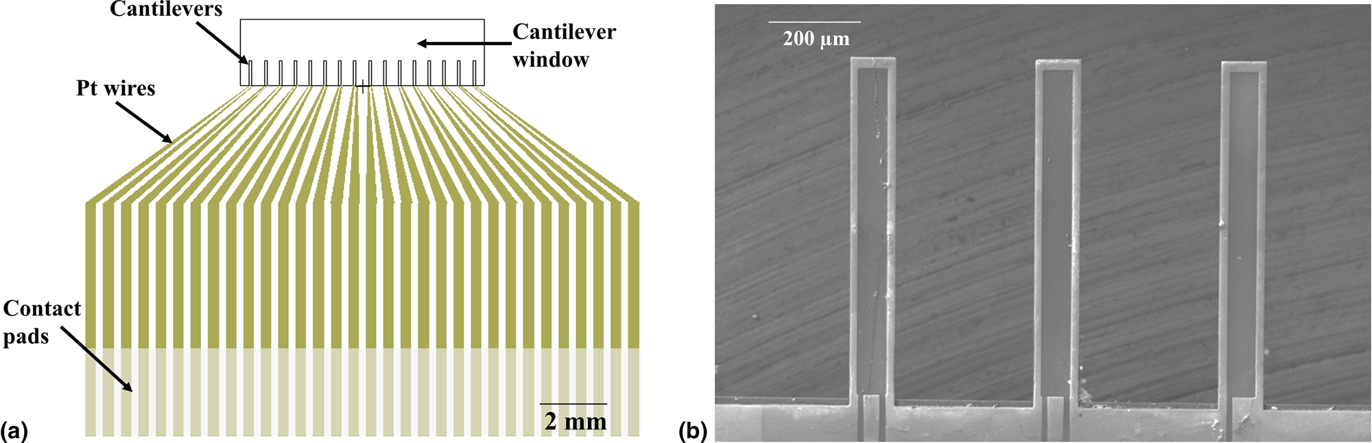
Piezoelectric cantilever devices were fabricated at the Cornell Nanoscale Science & Technology Facility (Ithaca, NY, USA) using standard microfabrication processes. Each chip included 16 individual microscale cantilevers each 100 µm wide, 750 µm long, and 4 µm thick with a total chip size of 17 mm × 14 mm. The 5-inch photomasks for each layer to produce the piezoelectric cantilevers were designed using L-edit layout editor (Tanner). For production of the devices, silicon oxide and silicon nitride layers were grown via plasma-enhanced chemical vapor deposition (PECVD; GSI PECVD System, Novanta, Inc., Bedford, MA, USA); metal layers (titanium and platinum) were deposited via electron-beam evaporation (CHA Mark 50 e-Beam Evaporator, CHA Industries, Fremont, CA, USA); the aluminum nitride (AlN) was sputtered using an aluminum target in a nitrogen plasma environment (ATC Orion Sputter Deposition Tool, AJA International, Inc., Scituate, MA, USA); oxide and nitride layers were etched via reactive-ion etching (RIE; Oxford PlasmaLab 80+ RIE System, Oxford Instruments, Concord, MA, USA); the silicon device and handle layers were etched via deep reactive-ion etching (DRIE; Unaxis 770 Deep Silicon Etcher, Plasma-Therm, St. Petersburg, FL, USA); and photolithography was performed using a Karl Suss MA6 Mask Aligner (Suss Microtec SE, Garching, Germany). The fabrication process, starting from a silicon-on-insulator wafer with a 4 µm thick 〈100〉 silicon device layer, 1–2 µm buried oxide layer, and 500 µm handle wafer, is shown in Fig. 1, and focuses on the production, patterning, and electrical isolation of the sandwich structure of AlN between two platinum electrodes. A 1.5 µm thick silicon dioxide layer and 300 nm silicon nitride layer were deposited via PECVD on the back and front (device) sides of the wafer, respectively. The piezoelectric element consisting of an aluminum nitride layer sandwiched between two platinum electrodes was produced by evaporation and liftoff of the bottom metal layer (10 nm titanium and 50 nm platinum) [Fig. 1(a)], followed by reactive sputtering of 300 nm of aluminum nitride [Fig. 1(b)] and evaporation of a second electrode identical in composition and thickness to the first. Both the aluminum nitride and top electrode layers were patterned via a liftoff process [Fig. 1(c)]. An insulation layer of silicon oxide and silicon nitride was deposited on top of the device layer, including the piezoelectric element [Fig. 1(d)]. The insulation layer was patterned via RIE to expose the contact pads and allow etching to define the cantilevers [Fig. 1(e)]. DRIE was then used to define the cantilevers in the device layer silicon. To release the cantilevers and open a window through the wafer to the cantilevers, the oxide on the backside of the wafer was etched using RIE to create an etch mask for the DRIE process, which was used to perform a through etch of the handle wafer to the cantilevers. Buffered hydrofluoric acid (HF) was used to remove the buried oxide layer to fully release the cantilevers [Fig. 1(f)]. Each final cantilever is 100 µm wide and 750 µm long, with a piezoelectric cantilever element 80 µm wide and 730 µm long on the top of the silicon cantilever. In the piezoelectric cantilever chip design [Fig. 2(a)], each cantilever has an independent contact pad for the top and bottom platinum layers, and these contact pads are connected to an external amplifier. A JEOL 6400 scanning electron microscope (JOEL USA, Inc., Peabody, MA, USA) was used to measure cantilever dimensions [Fig. 2(b)].
Fabrication of piezoelectric cantilevers. (a) Ti/Pt bottom electrodes and contact pads were deposited on an SOI wafer with insulation layers on the front and backside and patterned via liftoff. (b) Piezoelectric AlN was reactively sputtered and patterned via liftoff. (c) Top metal electrodes and contact pads were deposited and patterned via liftoff. (d) Top insulation layer (ONO) was deposited via PECVD. (e) The insulation layer was patterned by RIE. (f) The front and backside were etched via DRIE to define and release the cantilevers, followed by an HF dip to remove the buried oxide layer.

Piezoelectric cantilever chip layout. (a) Piezoelectric cantilever chip design showing the location of cantilevers, wires, and contact pads. (b) SEM image of piezoelectric cantilevers showing the top surface of platinum and SiO2 insulation. Because the cantilever chip was not coated with a separate conductive layer, the piezoelectric element and platinum wires appear darker, as the adjacent insulation layers charge slightly under the electron beam.

Surface modification of piezoelectric cantilevers
Piezoelectric cantilevers were chemically modified with a diethlyenetriamine (DETA)-containing silane using previously published methods to enhance cell adhesion and functional development.[Reference Stancescu, Molnar, McAleer, McLamb, Long, Oleaga, Prot and Hickman3,Reference Das, Wilson, Molnar and Hickman24–Reference Wilson, Das, Wahl, Colton and Hickman26] Following chemical modification, the chips were incubated in human fibronectin (50 µg/mL) in phosphate-buffered saline (PBS) at 37 °C for 30 min just prior to cell plating to adsorb the fibronectin onto the DETA surface for cell attachment.
Cell culture on the piezoelectric cantilevers and housing system assembly
Commercially available, cryogenically preserved, human-induced pluripotent stem cell (iPSC)-derived cardiomyocytes (iCell Cardiomyocytes, #CMC-100-110-005, Cellular Dynamics International, Madison, WI, USA) were plated onto fibronectin-coated piezoelectric cantilevers (2200 cells/mm2) in a serum-free medium according to previously published methods that described culturing these cells on nonpiezoelectric bioMEMS cantilevers.[Reference Oleaga, Bernabini, Smith, Srinivasan, Jackson, McLamb, Platt, Bridges, Cai, Santhanam, Berry, Najjar, Akanda, Guo, Martin, Ekman, Esch, Langer, Ouedraogo, Cotovio, Breton, Shuler and Hickman2–Reference Oleaga, Riu, Rothemund, Lavado, McAleer, Long, Persaud, Narasimhan, Tran and Roles4,Reference Natarajan, Stancescu, Dhir, Armstrong, Sommerhage, Hickman and Molnar25] These cardiomyocytes in our serum-free culture system express a mature phenotype, have robust electrical and mechanical function, and show appropriate functional changes in response to drug compounds.[Reference Stancescu, Molnar, McAleer, McLamb, Long, Oleaga, Prot and Hickman3,Reference Oleaga, Riu, Rothemund, Lavado, McAleer, Long, Persaud, Narasimhan, Tran and Roles4,Reference Wilson, Das, Wahl, Colton and Hickman26,Reference Oleaga, Lavado, Riu, Rothemund, Carmona-Moran, Persaud, Yurko, Lear, Narasimhan and Long27] Every 2 days, one-half of the medium was replaced with fresh medium. The piezoelectric chips with cultured cardiomyocytes were maintained for 7 days prior to assembling into housings. System housings and gaskets were manufactured from 6 mm thick transparent poly(methylmethacrylate) (PMMA; McMaster-Carr, Elmhurst, IL, USA) and 0.5 mm thick poly(dimethylsiloxane) (Grace Bio-Labs, Bend, OR, USA), respectively. Both housings and gaskets were designed in Eagle (Autodesk) software and laser cut using a Versalaser PLS 75W laser cutter (Universal Laser Systems, Scottsdale, AZ, USA). The piezoelectric cantilevers were assembled within the PMMA top and bottom plates, with the gaskets sealing the contact pads from the cantilever area, which contained 500 µL of serum-free medium.
Contractile force measurement with piezoelectric cantilevers
A microelectrode array (MEA) amplifier (MEA 1040, Multichannel Systems, Reutlingen, Germany) was interfaced to the piezoelectric cantilever chip in the housing via a custom printed circuit board (PCB) and was used to record the electrical output from the piezoelectric cantilevers. For contractile force experiments, piezoelectric cantilever chips cultured with cardiomyocytes were assembled into system housings with 500 µL serum-free medium over the piezoelectric cantilevers. The force of the beating cardiomyocytes bent the cantilevers, producing mechanical stress in the piezoelectric aluminum nitride, in turn generating an electric potential difference across the two electrodes. This voltage was measured by the amplifier and recorded in real-time using a commercially available data acquisition software package (MC_Rack, Multichannel Systems, Reutlingen, Germany), and the voltage data were analyzed with Clampfit (Axon Instruments) software. To demonstrate the ability of the piezoelectric cantilever sensors to detect changes in cardiomyocyte function, the cardiomyocytes were dosed with 3 µM epinephrine to increase the beat frequency during the recording.
Immunocytochemical imaging of cardiomyocytes on piezoelectric cantilevers
Piezoelectric cantilevers were prepared for immunocytochemistry using methods that previously described staining these cells on nonpiezoelectric cantilevers and coverslips.[Reference Colón, Guo, Akanda, Cai and Hickman18,Reference McAleer, Long, Elbrecht, Sasserath, Bridges, Rumsey, Martin, Schnepper, Wang, Schuler, Roth, Funk, Shuler and Hickman28] Briefly, cells on the piezoelectric cantilevers were fixed with a 4% (vol/vol) paraformaldehyde/PBS solution for 10 min at room temperature. Cardiomyocytes were permeabilized for 15 min with 0.1% Triton X-100 and then blocked with 1% bovine serum albumin in PBS (blocking buffer) for 30 min at room temperature. Cells were incubated overnight at 4 °C with a mouse anti-myosin heavy chain primary antibody (Developmental Studies Hybridoma Bank, Iowa City, IA, USA) diluted 1:10 in blocking buffer. The cells were rinsed 3X with PBS for 15 min. The cells were incubated with Alexa Flour 488 (Invitrogen, Carlsbad, CA, USA) secondary antibodies (1:200 diluted in blocking buffer) and Phalloidin-568 (1:40) (A12380, Life Technologies, Carlsbad, CA, USA) for 2 h at room temperature. The stained samples were then rinsed with PBS for 20 min, 0.01% Triton X-100 and DAPI (Thermo Fisher P36931) for 30 min, and PBS for 15 min and imaged using a Zeiss LSM 510 confocal microscope.
Detection system for actuation of piezoelectric cantilevers
For actuation experiments, acellular piezoelectric cantilever chips were assembled into system housings with 500 µL of PBS and interfaced through a custom PCB to a Model 2100 Isolated Pulse Stimulator (A-M Systems, Sequim, WA, USA). A single cantilever was stimulated at a time by connecting the two electrode pads to the stimulator through the PCB. Two pulse shapes were applied to the piezoelectric cantilever: a monophasic square pulse (5 V, 150 ms duration, and 0.6 Hz), and a biphasic square pulse (±5 V, 300 ms duration, and 0.6 Hz). A previously described optical detection system[Reference Oleaga, Bernabini, Smith, Srinivasan, Jackson, McLamb, Platt, Bridges, Cai, Santhanam, Berry, Najjar, Akanda, Guo, Martin, Ekman, Esch, Langer, Ouedraogo, Cotovio, Breton, Shuler and Hickman2–Reference Oleaga, Riu, Rothemund, Lavado, McAleer, Long, Persaud, Narasimhan, Tran and Roles4,Reference McAleer, Long, Elbrecht, Sasserath, Bridges, Rumsey, Martin, Schnepper, Wang, Schuler, Roth, Funk, Shuler and Hickman28] was used to measure the deflection of the piezoelectric cantilever. In this system, a 635 nm laser (CPS635 F, Thorlabs, Newton, NJ, USA) and linear effect photodetector (PSD9, Thorlabs, Newton, NJ, USA) were located under a fixed stage and were aligned such that the laser was focused onto the tip of the underside of the cantilever. The laser was subsequently reflected onto the center of the photodetector to measure the deflections of the cantilevers as a change in position of the reflected laser spot on the photodetector. The deflection at the tip of the cantilever was then determined using methods described in Pirozzi et al. for this system.[Reference Pirozzi, Long, McAleer, Smith and Hickman29]
To understand the cantilever deflection when stimulated electrically as an actuator, a mathematical relationship between the input pulses and the average deflection signals was developed. The deflection curves for the monophasic stimuli were averaged, as were those for the biphasic stimuli. The induced strain in a piezoelectric material is approximately linearly proportional to the electric field across the piezoelectric element, as shown in Eq. (1), where ε is the strain in the piezoelectric material, d is the piezoelectric coefficient, and E is the electric field for the inverse effect.
 $$\varepsilon = d \times E$$
However, the electric field across the element is related not only to the voltage applied to the electrode pads and geometric configuration but also the resistive and capacitive elements in the circuit, including those of the piezoelectric aluminum nitride element. The input voltage is effectively filtered in a similar way as a low pass RC filter in producing the actuation. As all of the input voltage changes used in this study were step functions (increasing and decreasing), the differential equation for the effect of an RC filter has a simple time-domain solution, forming the basis of the following equation:
 $$\Delta \delta = A\Delta V_{{\rm pulse}}\lpar {1 - e^{ - t/\tau}} \rpar $$
where Δδ is the change in position (deflection) of the tip of the cantilever; A is the parameter relating the voltage across the AlN element to the cantilever deflection and is related to the piezoelectric coefficient and physical layout of the device; ΔV pulse is the change in voltage of the input step function; t is the time since the square wave initiation; and τ is the time constant of the circuit. The measured deflection from the optical detection system was fit to Eq. (2) using a least-squares regression method to determine A and τ.
Results and discussion
Piezoelectric sensing for cardiomyocyte force measurements
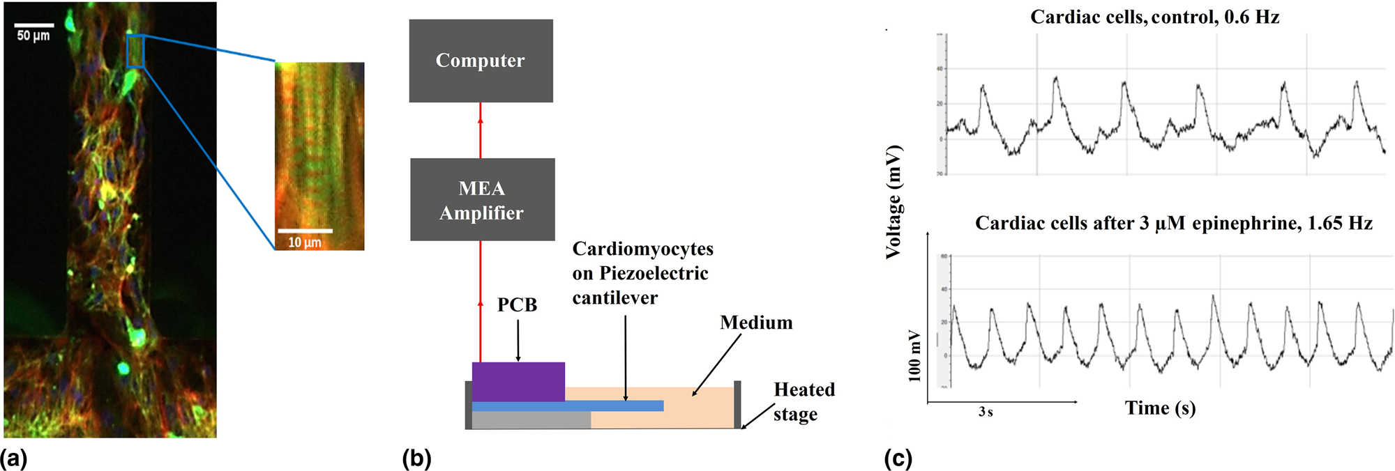
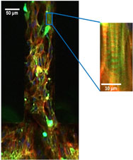
To demonstrate that the piezoelectric cantilevers could produce electrical signals from cardiomyocyte contraction, the human iPSC-derived cardiac muscle was grown on the piezoelectric cantilevers in the serum-free medium. This bioMEMS device is a hybrid 3D structure with a monolayer of cardiomyocytes grown directly on top of the cantilever. In previous studies, we have shown that the structure of cardiomyocytes and skeletal muscle on nonpiezoelectric versions of these cantilevers enables both the correct formation of the cellular microstructure and the measurement of the contractile function and that this format enables measurement of the effects of drug compounds with results similar to what is expected from in vivo experiments.[Reference Oleaga, Bernabini, Smith, Srinivasan, Jackson, McLamb, Platt, Bridges, Cai, Santhanam, Berry, Najjar, Akanda, Guo, Martin, Ekman, Esch, Langer, Ouedraogo, Cotovio, Breton, Shuler and Hickman2–Reference Oleaga, Riu, Rothemund, Lavado, McAleer, Long, Persaud, Narasimhan, Tran and Roles4,Reference Oleaga, Lavado, Riu, Rothemund, Carmona-Moran, Persaud, Yurko, Lear, Narasimhan and Long28,Reference McAleer, Smith, Najjar, Pirozzi, Long and Hickman30] Confocal microscopy of the cardiomyocytes on the piezoelectric cantilevers [Fig. 3(a)] indicates immunocytochemical analysis of the cardiomyocytes cultured on the cantilevers with the contractile proteins phalloidin (actin, red) and myosin heavy chain (green) as well as staining for the nuclei (blue) visible. These cell culture results were substantially the same as in our previous work published in Stancescu et al. in which the cardiomyocytes were extensively characterized and have similar surface chemistry and device geometry as in this study.[Reference Stancescu, Molnar, McAleer, McLamb, Long, Oleaga, Prot and Hickman3] In addition, we have shown the systems are stable for up to 28 days for both cardiomyocytes and skeletal muscle.[Reference Wilson, Das, Wahl, Colton and Hickman26] These cardiomyocytes formed a syncytium of contracting cardiomyocytes, and this syncytium beat spontaneously due to the presence of pacemaker cells in the culture. Using the direct piezoelectric effect, the piezoelectric cantilevers converted the mechanical strain caused by the cardiomyocyte contraction into an electrical output. Figure 3(b) shows a simplified schematic of the MEA amplifier system setup used for cardiomyocyte force measurements. The real-time, continuous electrical signals generated by the piezoelectric AlN, in response to the cardiomyocyte tissue bending of the cantilever, were recorded when the PCB was connected to an external amplifier. To demonstrate that the system was capable of measuring changes in cardiomyocyte function, 3 µM epinephrine was added to the medium to increase the beat frequency of the cardiomyocytes.[Reference Grosberg, Alford, McCain and Parker31] Upon addition of epinephrine, the change in cardiomyocyte beat frequency was clearly observed, with an increase in frequency by a factor of more than two. Figure 3(c) indicates clear peak shapes with measurable amplitude and frequency for both the spontaneous cardiomyocyte contractions (top) and for the cardiomyocyte contractions induced by the addition of epinephrine (bottom).
Sensing of muscle contraction using piezoelectric cantilevers. (a) Confocal image of cardiomyocytes on a piezoelectric cantilever with phalloidin (actin) shown in red, myosin heavy chain in green, and DAPI in blue. (b) Schematic of recording setup for cardiomyocyte force measurements using piezoelectric cantilevers. (c) Measurement of cardiomyocytes on piezoelectric cantilevers showing control (top) and after treatment with the addition of 3 µm epinephrine (bottom).

Actuation of piezoelectric cantilevers
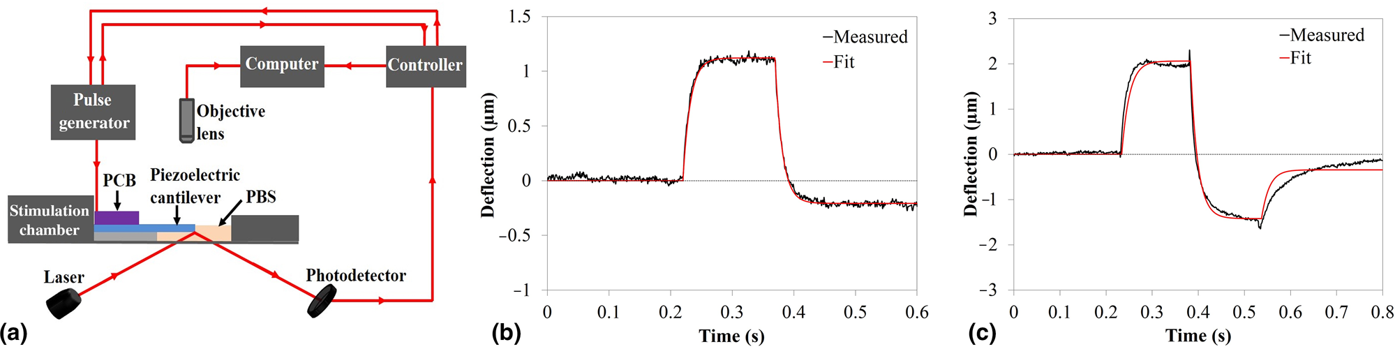
The ability of the piezoelectric cantilevers to serve as actuators for applying mechanical stress to tissue constructs was evaluated using an optical beam displacement method [Fig. 4(a)] to measure the deflection of the piezoelectric cantilevers under a periodic waveform of the applied voltage. Using the inverse piezoelectric effect, when the electric signal was applied to the piezoelectric aluminum nitride element, the aluminum nitride converted the electrical pulse into a mechanical deformation, causing the cantilever to bend. The actuation of the piezoelectric cantilevers was modeled electrically following a simple RC circuit[Reference Liu, Feng, Liu and Zhang32] and captures the capacitance of the platinum/aluminum nitride/platinum stack as well as the bulk resistance of the aluminum nitride and the resistance of the wires and other series elements in the circuit. Because of the effective resistance and capacitance of the circuit, the shape of the input actuation signal was not exactly reflected in the actuated cantilever beam. A transfer function model relating the output deflection to the input voltage signal was determined to better understand the behavior of the piezoelectric cantilevers as actuating elements and to help determine input functions to produce desired deflection waveforms. Figures 4(b) and 4(c) show the recorded cantilever deflection (black) of the 5 V monophasic square wave input and 5 V biphasic square wave, respectively, and the modeled transfer function (red) for each stimulation input. In both the monophasic and biphasic stimulations, the modeled transfer function very closely resembles the stimulated actuation signal. There is a slight offset in the actuation signals for both the monophasic and biphasic stimulations due to the baseline drift in the raw data as shown in Supplementary Figs. S1(a) and S1(b). Fitting these two models separately, the monophasic and biphasic models had an average τ of 0.014 s and average A of 0.31 µm/V.
Actuation of piezoelectric cantilevers. (a) Schematic of optical deflection system. (b) Piezoelectric cantilever actuation under a 5 V monophasic (150 ms) stimulation pulse. (c) Piezoelectric cantilever actuation under a ±5 V biphasic (total duration 300 ms) stimulation pulse. Slight offset observed at the end of actuation in (a and b) due to baseline drift in raw data (Supplementary Fig. S1).

For use with mechanosensitive cells, such as intrafusal skeletal muscle fibers innervated by sensory neurons as part of the stretch reflex arc, simple functions, such as square waves, are not sufficient to mimic physiological strain profiles needed to trigger sensory neuron action potentials. Instead, an isometric contraction profile would be desired to stretch the intrafusal fibers to activate the mechanoreceptors in the sensory neuron's axons to initiate an action potential. The transfer function between the time-dependent input voltage and time-dependent deflection, developed here, could be used to generate the required input waveform to produce the desired output deflection. Equation (3) relates the required applied voltage waveform to the desired voltage across the piezoelectric element for an arbitrary waveform:
 $$V_{{\rm applied}}\lpar t \rpar = \tau \displaystyle{{dV_{\rm AlN}\lpar t \rpar } \over {dt}} + V_{\rm AlN}\lpar t \rpar $$
where V applied(t) is the input voltage waveform, τ is the time constant (0.014 s), and V AlN(t) is the voltage across the AlN element. As the deflection of the cantilever tip is related to the voltage across the AlN element according to the inverse piezoelectric effect:
 $$\delta \lpar t \rpar = AV_{\rm AlN}\lpar t \rpar,$$
Equation (3) can be modified to relate the output deflection and voltage applied as time series:
 $$V_{{\rm applied}}\lpar t \rpar = \displaystyle{1 \over A}\left( {\tau \displaystyle{{d\delta \lpar t \rpar } \over {dt}} + \delta \lpar t \rpar } \right)$$
where δ(t) is the desired deflection of the tip of the cantilever, and A and τ are as in Eq. (2). For an arbitrary desired actuation profile (δ(t)) such as to mimic an isometric muscle contraction, Eq. (5) can be used to determine the input voltage waveform needed. This indicates that the piezoelectric system could potentially be used to stimulate intrafusal fibers to generate action potentials in sensory neurons. This study lays the framework for future work on mechanosensitive cells utilizing a more complex cell culture system in which the proposed applications would involve mechanosensitive cells seeded onto the piezoelectric cantilevers in a similar format as was presented with the piezoelectric cantilevers used as a sensor.
Conclusion
This work demonstrates the development of a new method using piezoelectric cantilevers to measure contractile muscle force generation in human cells by acquiring a real-time, continuous, and direct electrical signal generated in the piezoelectric AlN, caused by the muscle tissue bending the cantilever. This sensor was able to detect spontaneous cardiac muscle contraction with enough sensitivity to observe changes in contraction frequency induced by the addition of epinephrine. The piezoelectric cantilevers were additionally shown to function as actuators, with a defined filtering effect of the input signal to cantilever deflection. The actuation experiments enabled the determination of coefficients relating to the input voltage waveform to cantilever deflection, which can be used to determine the required input voltage waveforms to produce a desired arbitrary actuation profile. The ability of these piezoelectric cantilevers to actuate opens the opportunity for use with mechanosensitive cells, such as those in the sensory segment of the stretch reflex arc to stretch intrafusal fibers. These piezoelectric cantilever devices, which were designed to be incorporated into body-on-a-chip systems, have the potential to enable functional experiments with mechanosensitive tissue structures such as those in the stretch reflex arc, to incorporate these tissues into body-on-a-chip devices, and to increase the throughput of measurements of cardiac and skeletal muscle mechanical function in body-on-a-chip devices for basic physiological investigations, pharmaceutical compound development, toxin detection, neurological and muscular disease modeling for therapeutic development, and predictive toxicology.[Reference Haring, Sontheimer and Johnson33,Reference Luni, Serena and Elvassore34] Integration of human skeletal muscle fibers on the piezoelectric cantilevers would enable a more robust method to study the human central nervous system and improve understanding of spinal cord injuries, diseases such as amyotrophic lateral sclerosis, prosthetic design, and rehabilitative treatments.
Supplementary material
The supplementary material for this article can be found at https://doi.org/10.1557/mrc.2019.129.
Acknowledgements
This work was funded by the National Institutes of Health (Grant numbers 1R44TR001326, 2R44TR001326, and 5R01NS050452). This work was performed in part at the Cornell NanoScale Science & Technology Facility (CNF), a member of the National Nanotechnology Coordinated Infrastructure (NNCI), which is supported by the National Science Foundation (Grant NNCI-1542081).