


1. Introduction
The capability to improve the efficiency of mixing processes by employing starting jets has been widely recognised. This can be ascribed to the thus generated vortex rings that are associated with greater entrainment rates than those found in steady jets. Extensive reviews regarding the structure and motion of vortex rings for different boundary conditions are provided by Shariff & Leonard (Reference Shariff and Leonard1992) and Lim & Nickels (Reference Lim, Nickels and Green1995). Two mechanisms are responsible for their entrainment of ambient fluid. First, there is a continuous circulatory engulfment of large regions of surrounding fluid (convective entrainment) and second, shearing takes place at the interface between the vortex ring and the irrotational surrounding fluid, resulting in viscous diffusion (diffusive entrainment).
The characteristics of starting jets are reflected in the invariants of motion, i.e. the circulation  $\varGamma$, the kinetic energy
 $E$ and the impulse
 $I$. Among these quantities, the circulation is particularly important to the purpose of this study. As noted by Didden (Reference Didden1979), its rate of change is equal to the vorticity flux ejected through the jet exit plane, i.e.
 \begin{equation} \frac{\mathrm{d}\varGamma}{\mathrm{d}t} = \int_0^{y_\infty} u\omega_z \,\mathrm{d}y \end{equation}
when only convective transport is regarded, i.e. diffusive effects are neglected. Here, a general two-dimensional starting jet is assumed where  $u$ is the axial jet velocity and
 $y$ points along the lateral jet direction with the integration boundaries
 $y=0$ on the centreline and
 $y=y_\infty$ at a sufficient distance so as to ensure a vanishing vorticity flux. The out-of-plane vorticity component is
 $\omega _z = \partial v/\partial x - \partial u/\partial y$ where the second term only depends on the centreline velocity
 $u_0$, and hence can be determined without knowledge of the specific axial velocity profile (see Didden Reference Didden1979; Rosenfeld, Rambod & Gharib Reference Rosenfeld, Rambod and Gharib1998). As a result, (1.1) is transformed to
 \begin{equation} \frac{\mathrm{d}\varGamma}{\mathrm{d}t} = \int_0^{y_\infty}u \frac{\partial v}{\partial x} \,\mathrm{d}y + \frac{1}{2} u_0^2. \end{equation}
Assuming a uniform axial velocity at the outlet and parallel flow in the exit plane, i.e. a zero transverse velocity component  $v$ for all times, the first term on the right-hand side can be neglected. This amounts to the slug model that is commonly used for the prediction of circulation development (Shariff & Leonard Reference Shariff and Leonard1992; Glezer Reference Glezer1998).
Based on this model for parallel starting jets, Gharib, Rambod & Shariff (Reference Gharib, Rambod and Shariff1998) explain the existence of a time scale that governs the efficient formation of vortex rings. Essentially quantifying the amount of emitted fluid, they show that a specific ratio of stroke length and outlet diameter  $L/d \approx 4$, which is dubbed formation number by the authors, separates two regimes of vortex ring appearance: at low stroke ratios, the majority of the vorticity generated by the starting jet occurs in a leading vortex ring whereas for higher stroke ratios, there is no further increase of the vortex ring circulation but it is now followed by a trailing jet. They argue that vortex rings of maximum circulation are characterised by a set-up-specific dimensionless energy
 \begin{equation} \alpha_{lim} = \frac{E}{\varGamma^{3/2} I^{1/2}}\end{equation}
that is linked with the vorticity distribution inside the vortex ring. This distribution in turn is dependent on the piston velocity signal, i.e. the history of the starting jet velocity in the exit plane. Readily extractable from particle image velocimetry (PIV) measurements, they find that the generated steady vortex rings exhibit nearly constant non-dimensional energies of  $\alpha _{lim} = 0.33\pm 0.01$ once the formation number is exceeded. They compare this empirical quantity to the non-dimensional energy supplied by the apparatus
 $\alpha _{piston}$ and observe the following: as the stroke ratio is increased,
 $\alpha _{piston}$ decreases, which results in greater vortex ring dimensions. For stroke ratios greater than
 $L/d \approx 4$,
 $\alpha _{piston}$ falls below
 $\alpha _{lim}$ in their experiment, and ‘the apparatus is no longer able to deliver energy at a rate compatible with the requirement that a steadily translating vortex ring have maximum energy with respect to impulse-preserving iso-vortical perturbations’ (Gharib et al. Reference Gharib, Rambod and Shariff1998). This implies that there is an upper threshold in the amount of fluid that can be converted into a single vortex structure. This conclusion and the universality of the formation number were shown to be applicable across a broad range of operating parameters for parallel starting jets, e.g. by Rosenfeld et al. (Reference Rosenfeld, Rambod and Gharib1998), Dabiri & Gharib (Reference Dabiri and Gharib2004), Krueger, Dabiri & Gharib (Reference Krueger, Dabiri and Gharib2006), Pawlak et al. (Reference Pawlak, Cruz, Bazan and Hrdyi2007), Mohseni, Ran & Colonius (Reference Mohseni, Ran and Colonius2000) and Sau & Mahesh (Reference Sau and Mahesh2007). To avoid explicit measurements of
 $\alpha _{lim}$, Mohseni & Gharib (Reference Mohseni and Gharib1998) introduce an analytical model to predict the formation number based on the non-dimensional energy and circulation. This is accomplished by equating the invariants of motion for the family of steady vortex rings defined by Norbury (Reference Norbury1973) and the corresponding quantities provided by the slug model.
Although the parallel flow assumption of the slug model may be applicable to many configurations where a fluid column is emitted into quiescent surroundings, it is also observed that the model can under-predict the vortex ring circulation substantially, e.g. by Didden (Reference Didden1979), Nitsche & Krasny (Reference Nitsche and Krasny1994), James & Madnia (Reference James and Madnia1996), Weigand & Gharib (Reference Weigand and Gharib1997) and Zhao, Fraenkel & Mongeau (Reference Zhao, Fraenkel and Mongeau2000). According to Krueger (Reference Krueger2005), this under-prediction is linked with a peak in the circulation flux  $\mathrm {d} \varGamma /\mathrm {d} t$ (1.1) and (1.2) that can occur during the initial rapid acceleration of fluid. During this phase, a non-uniform axial velocity distribution is found in the outlet plane characterised by a maximum at the nozzle lip, coinciding with a peak in
 $\partial v / \partial x$ (Didden Reference Didden1979). In establishing a relationship between the non-zero transverse velocity component and over-pressure inside the jet exit plane, Krueger (Reference Krueger2005) introduces a correction term for the slug model
 \begin{equation} \varGamma_p = \frac{1}{\varrho}\int_0^{t_{p}}(p_0-p_\infty)\,\mathrm{d}t, \end{equation}
where  $p_0$ denotes the centreline pressure inside the jet exit plane and
 $p_\infty$ is the ambient pressure. Neglecting viscous effects, this correction term is equal to the temporal integral of the first term on the right-hand side in (1.2) and can be viewed as a manifestation of non-parallel flow. Hence, over-pressure inside the outlet plane during the rapid jet initiation is responsible for two interrelated effects. First, it leads to an enhanced vorticity flux, thus larger overall circulation. Second, it imposes a curvature of streamlines close to the jet outlet, i.e. a transverse advection of fluid.
For the classical approach of generating vortex rings in the laboratory, a piston–cylinder arrangement is used to accelerate a defined amount of fluid and emit it into a water tank. However, more relevant to technical implementations in the field of active flow control (AFC) are pulsed jet actuators (PJAs) which periodically emit pressurised air in an impulsive fashion. The periodic flow manipulation is brought about either by a solenoid valve or a fluidic switching mechanism and among other devices, such as synthetic jet or plasma actuators, they may be used to control flow separation (Greenblatt & Wygnanski Reference Greenblatt and Wygnanski2000). For PJAs, the over-pressure is typically larger than for the piston–cylinder set-up, resulting in a greater transverse flow acceleration. Furthermore, the jet outlets are typically not circular but slit shaped so as to efficiently affect greater flow regions. So far, the concept of a formation number was found to be not readily applicable to planar two-dimensional starting jets (Pedrizzetti, Domenichini & Tonti Reference Pedrizzetti, Domenichini and Tonti2010). This was generally explained by the observation made by Afanasyev (Reference Afanasyev2006) and later by Das, Govardhan & Arakeri (Reference Das, Govardhan and Arakeri2013) that there is no clear separation between the produced vortex pair and the trailing jet (pinch-off) as the former does not acquire a sufficiently large translational speed. Hence, there is an ongoing interaction as the vortex dipole continues to entrain vorticity from the trailing jet even when the formation number of  $L/d\approx 4$ is surpassed. It must be noted, however, that these investigations were also restricted to the generation of vortical structures by means of a piston–cylinder apparatus whereas the literature concerned with fundamental properties of vortex rings generated with PJAs or other flow control devices is sparse. For the specific case of synthetic jet actuators, Smith & Glezer (Reference Smith and Glezer1998) show that the centreline velocity decay is greater while the spreading rate is lower in comparison to steady jets. The trajectories of vortex cores related to flow structures induced by planar synthetic jets are investigated by Béra et al. (Reference Béra, Michard, Grosjean and Comte-Bellot2014). Focusing on purely alternating jets and mixed pulsed jets, they note that vortex structures develop farther from the jet orifice when the velocity is not decreased to zero between successive starting jets. Choutapalli, Krothapalli & Arakeri (Reference Choutapalli, Krothapalli and Arakeri2009) study the properties of a pulsed axisymmetric jet at high Reynolds numbers that is generated by means of a rotating disk with drilled holes that allow the flow to enter the nozzle whereas the path is closed otherwise. As the duty cycle is defined by the ratio of open to closed area, a greater Strouhal number results in a closer distance between successive vortex rings in their experiment with a steady jet character assumed at a distance of five nozzle diameters. They also note distinct deviations when analysing characteristic turbulent quantities in separate regions of the pulsed jet as the vortex ring appears to boast greater shearing stresses than the trailing jet. A recent direct numerical simulation study by Shin, Aspden & Richardson (Reference Shin, Aspden and Richardson2017) is concerned with a suddenly stopped, hence decelerating axisymmetric jet. The authors suggest that behind the deceleration wave, a statistically unsteady self-similar state can be noted, building on the experimental work by Witze (Reference Witze1983) who studied the velocity field of an impulsively started axisymmetric jet and a simplified analytical approach by Musculus (Reference Musculus2009) addressing the entrainment rate during the deceleration phase of a single-pulsed jet.
The main objective of this study is to reveal the properties of vortex rings associated with non-parallel planar starting jets that are generated with an AFC-typical device. In doing so, we also examine the hypothesis that the concept of a formation number proposed by Gharib et al. (Reference Gharib, Rambod and Shariff1998) can be extended to this flow configuration. This is motivated by the fact that past studies have mainly been concerned with parallel starting jets of presumably similar limiting non-dimensional energies  $\alpha _{lim}$. However, the influence of highly non-parallel flow on this parameter, essentially defining the formation number, has not been studied to the best of our knowledge. Here, a PJA is employed, and driven by a solenoid valve, the flow periodically exits a
 $20\ \mathrm {mm} \times 0.5\ \mathrm {mm}$ rectangular outlet. The over-pressure required to provide relevant jet velocities of
 $u_{jet}\approx 50\ \mathrm {m}\,\textrm {s}^{-1}$ is substantial due to the short valve opening durations. Hence, highly non-parallel flow is present close to the outlet of the starting jets.
The vortex rings generated with this set-up are mainly studied on the basis of phase-locked PIV measurements while flow visualisations of starting jets ejected into a water tank are conducted as a reference case. A detailed description of the set-up and procedure is provided in the following.
2. Methods
This section contains a description of the experimental approach. Two set-ups were used for this work: (i) A PJA system was employed to generate non-parallel planar starting jets of compressed air. (ii) The classical piston–cylinder set-up was utilised to produce vortex rings associated with parallel starting jets in a water tank. Thus, the influence of the non-parallel flow condition can be identified by comparing results from the two experiments.
2.1. Non-parallel starting jets generated with PJA device
2.1.1. Experimental procedure
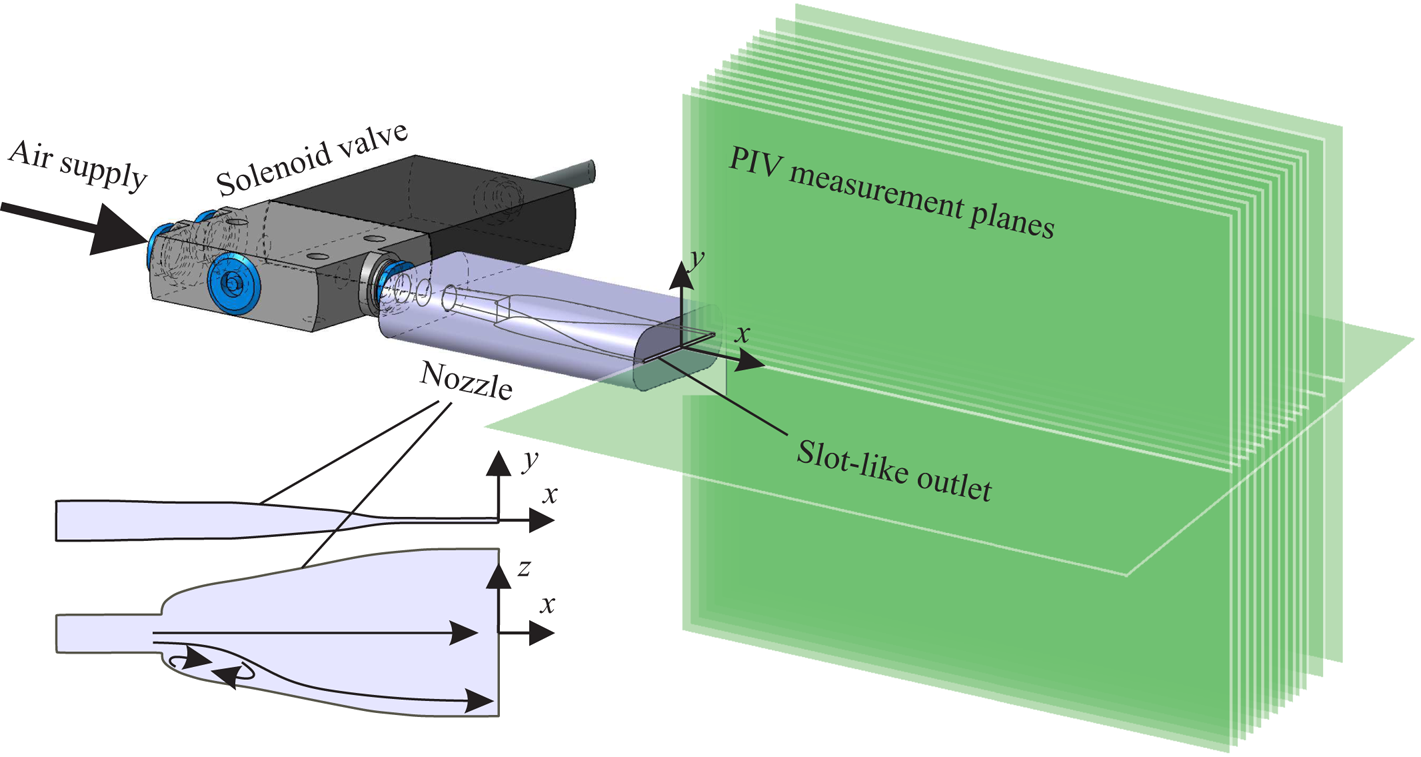
The PJA device that was used to generate non-parallel starting jets was mainly composed of a mechanical valve and a nozzle with a rectangular slit-shaped outlet that was mounted flush in a wall. Pressurised air was fed through the solenoid valve with a minimum opening time of  $t_{p,min} = 0.6 \ \mathrm {ms}$ that was operated at
 $f_{p} = 50\ \mathrm {Hz}$. The accuracy with respect to the valve opening time was
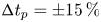 ${\rm \Delta} t_{p}=\pm 15\,\%$. As shown in figure 1, the inlet consists of a circular tube, connecting the nozzle and the solenoid valve. Then, a transition from circular to rectangular cross-section ensues. This is accompanied by a sudden widening of the flow area in
 $z$ direction which may result in a minor recirculation region associated with a bending separating streamline. The resulting velocity profiles close to the outlet will be analysed later on.
Arrangement of solenoid valve and nozzle with outlet aspect ratio of  $l/d=40$ for generation of non-parallel planar starting jets.

The slit-shaped outlet had a width of  $d = 0.5 \ \mathrm {mm}$ and a length of
 $l = 20 \ \mathrm {mm}$. Based on a circle with the same area, this yields an equivalent diameter of
 $d_{eq}\approx 3.57\ \mathrm {mm}$. Ensuring an equal volumetric flux, this quantity is used as the characteristic length scale in the current study. For other non-circular, namely elliptic, jets Hussain & Husain (Reference Hussain and Husain1989) found that this definition yields an adequate length scale. Furthermore, it was used in the study of the pinch-off process of vortex rings generated with elliptic jets by O'Farrell & Dabiri (Reference O'Farrell and Dabiri2014).
The nominal velocity of the jets  $u_{jet}$ was calculated based on mass conservation taking into account the outlet area, valve opening time and a constant supply mass flow. The latter was adjusted with a controller and fed into a tank upstream of the solenoid valve with a volume sufficiently large to compensate velocity fluctuations. The stroke ratio of the planar starting jets
 $L/d_{eq}$ was varied by adjusting the pulse width and thus changing the length of a virtually emitted fluid column
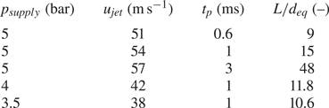
 $L=u_{jet}t_{p}$. Three configurations encompassing relevant formation time scales for the specific starting jets studied here were narrowed down in preliminary experiments and will be discussed throughout the paper, see table 1. Specifically, equivalent stroke ratios of
 $L/d_{eq}\approx [9,15,48]$ were investigated. Given the actuation frequency of
 $f_{p} = 50\ \mathrm {Hz}$, these configurations are associated with duty cycles of
 ${\textrm {DC}}=[3,5,15]\%$. Operating the PJA device at such relatively low duty cycles means that fluid is almost completely at rest before the valve is opened. A substantial gradient force, driven by a supply pressure of roughly
 $p_{supply}\approx 5\ \mathrm {bar}$, is necessary to ensure the required acceleration to reach AFC-relevant jet velocities listed in table 1. This rapid acceleration is the source for non-parallel flow effects that are specific to the method of generating vortex rings in the current study and will be addressed in more detail in the following. To assess the influence of these effects, two further configurations with a decreased supply pressure of
 $p_{supply}\approx 4\ \mathrm {bar}$ and
 $p_{supply}\approx 3.5\ \mathrm {bar}$ were investigated. The valve opening time for these configurations was the same as for the medium stroke ratio, i.e.
 $t_{p}\approx 1\ \mathrm {ms}$. This resulted in decreased jet velocities and stroke ratios that are also listed in table 1.
Main parameters of investigated non-parallel starting jet configurations.

As indicated in figure 1, two-dimensional velocity fields were measured by means of stereoscopic PIV in 13 parallel planes at  $z = 0,-2, \ldots ,-20,-25,-30 \ \mathrm {mm}$. The gathered velocity information was then mirrored around the
 $z = 0 \ \mathrm {mm}$ plane as symmetry was verified by measuring additional planes at
 $z = 6 \ \mathrm {mm}$ and
 $z = 12 \ \mathrm {mm}$. The resulting PIV domain had dimensions of
 $X \approx 100\ \mathrm {mm}$,
 $Y \approx 90\ \mathrm {mm}$ and
 $Z \approx 60\ \mathrm {mm}$. As indicated in figure 1, further measurements were also conducted inside the
 $xz$ symmetry plane.
The measurement domain was filled with Dioctyl sebacate (DEHS) particles of  $d_{\mathrm {DEHS}} \approx 1\ \mathrm {\mu } \mathrm {m}$ diameter with an external seeding generator prior to measurements. However, particles were also added to the air supply of the PJA as to ensure a sufficient seeding density inside the starting jets in close outlet proximity. Particle slip due to dynamic forces induced by periodic oscillations present inside the flow field was expected to be negligible in accordance with considerations given by Mei (Reference Mei1996).
The cameras had an optical resolution of  $2560 \times 2160\ \mathrm {px}^{2}$, and each measurement plane was divided into square overlapping interrogation areas with an edge length of 24 pixels, resulting in a spatial resolution of
 ${\rm \Delta} x = {\rm \Delta} y \approx 0.52 \ \mathrm {mm}$. With respect to the rising edge driving the solenoid valve, a dual-pulsed laser was triggered at 60 different time delays, equidistantly sampling the actuation process with a period of
 $T = 1/f_{p} = 20\ \mathrm {ms}$. Thus, the temporal resolution of PIV measurements was
 $\mathrm {d}t \approx 0.33 \ \mathrm {ms}$. Further measurements with an increased temporal resolution of
 $\mathrm {d}t \approx 0.05 \ \mathrm {ms}$ during fluid emission were performed for an opening duration of
 $t_{p} = 1\ \mathrm {ms}$ inside the
 $xy$ symmetry plane to analyse the early vortex ring evolution process in more detail. The spatial resolution for those measurements was
 ${\rm \Delta} x = {\rm \Delta} y \approx 0.75 \ \mathrm {mm}$. For each configuration, about 70 double images of the illuminated particles were taken per phase, which resulted in an average standard deviation of
 $u_{c,std} \approx 0.11\ u_{c}$ on the jet centreline.
The moment when seeding particles first emerged from the nozzle was defined to be  $t=0\ \mathrm {ms}$. Essentially quantifying the consumption of compressed air over time, the non-dimensional formation time
 $t^*=(t u_{jet})/d_{eq}$ is referred to in this article. Note that the time instance up to which fluid is nominally emitted is marked by
 $t^*=L/d_{eq}$.
2.1.2. Degree of non-parallel flow
Due to the substantial acceleration of fluid mentioned above, over-pressure effects can be expected to govern the flow configuration. These are associated with highly non-parallel flow as opposed to starting jets generated with a piston–cylinder apparatus. In this section, we qualify the specific flow scenario by focusing on relevant properties in the near-outlet region.
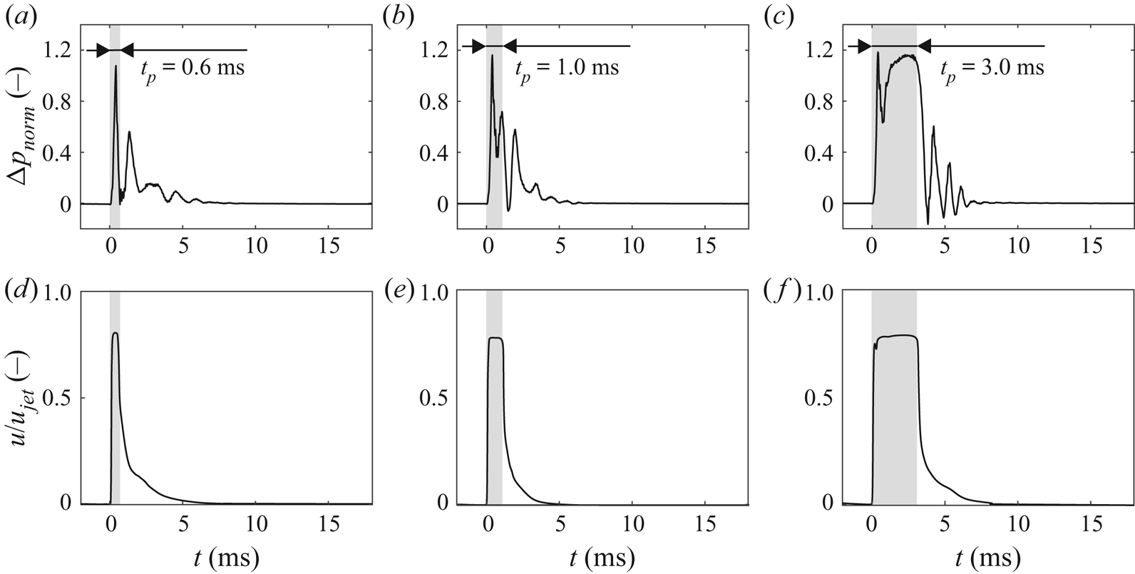
The phase-averaged pressure and velocity signals close to the nozzle outlet are shown in figure 2 over the time of one actuation period where shaded regions indicate durations equal to the respective valve opening times.
Pressure and velocity signals close to the centre of jet exit plane for three stroke ratios; pulse width  $t_{p}$ highlighted by shaded area for reference. (a,d)
 $L/d_{eq} \approx 9$, (b,e)
 $L/d_{eq} \approx 15$ and (c,f)
 $L/d_{eq} \approx 48$.

The static pressure was measured using a piezo-resistive pressure transducer with a sensitivity of  $S\approx 0.03\ \mathrm {mV}\,\textrm {Pa}^{-1}$ and a range of
 $p_{max} = 0\text{--}6.9\ \mathrm {kPa}$ mounted directly under the nozzle surface at
 $x = -2\ \mathrm {mm}$. The time-resolved signals are therefore deemed representative of the pressure in the jet exit plane. All of the investigated starting jets are characterised by distinct over-pressure of
 ${\rm \Delta} p_{norm}=(p-p_\infty )/(\varrho u_{jet}^2)>1$. An initial short-duration peak is observed for all configurations whereas a secondary pressure wave only follows for the two larger stroke ratios. A similar initial peak was also observed by Krieg & Mohseni (Reference Krieg and Mohseni2015) who conducted force measurements on a water jet actuator. In their experiment, the peak in force was much more distinct when the fluid was accelerated in an impulsive fashion as opposed to sinusoidal velocity programs, indicating the significance of a rapid jet initiation. Compared to experiments with a piston–cylinder apparatus, however, the magnitude of over-pressure is much larger in the current study as for instance, Krieg & Mohseni (Reference Krieg and Mohseni2013) report a non-dimensional over-pressure of only
 ${\rm \Delta} p_{norm}\approx 0.2$. Therefore, a larger contribution of the over-pressure term (1.4) to the overall circulation can be expected.
Based on a point measurement with a hot-wire anemometry (HWA) probe at  $x\approx 2\ \mathrm {mm}$, an impulsive acceleration can be observed in the velocity signals. However, it is worth noting that this does not necessarily reflect the Lagrangian acceleration of fluid particles due to the large pressure gradient. The peak velocities are almost constant but smaller than the nominal jet velocities (table 1). This is mainly due to the calculation of the latter quantity which is based on a square-wave signal with a constant velocity high that is limited to the pulse width
 $t_{p}$. This is clearly not reflected in the velocity signal at
 $x\approx 2\ \mathrm {mm}$ where a deceleration wave can be observed to follow the starting jet. The actual duration of fluid ejection is therefore longer than
 $t_{p}$, hence a smaller peak velocity is found for the given mass flow rate.
In conclusion, the flow is dominated by large over-pressure in the jet exit plane which causes a rapid acceleration of fluid. In the following, we address the influence of these boundary conditions on quantities that can be directly related to the early formation process of vortex rings. Since the pressure and velocity signals are very similar at the onset of fluid emission for all stroke ratios, only information for one configuration ( $L/d_{eq}\approx 15$) is provided.
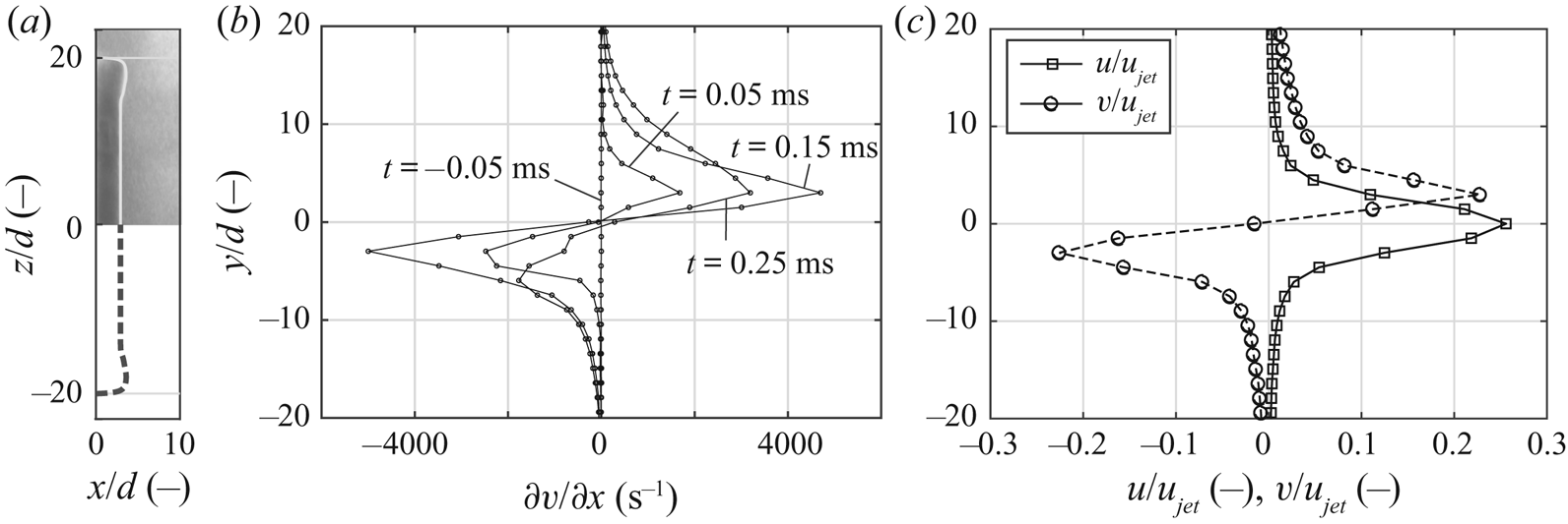
Figure 3 sheds light upon the velocity gradient distributions close to the jet exit plane. An almost uniform axial velocity distribution is observed at  $t=0\ \mathrm {ms}$ inside the
 $xz$ symmetry plane, i.e. along the larger dimension of the outlet (in figure 3a). The flow visualisation shown for
 $z/d>0$ was achieved by illuminating this plane and recording roughly 100 images at
 $t=0\ \mathrm {ms}$ that were averaged subsequently. Seeding particles were added to the quiescent ambient fluid but not to the PJA supply, enabling a distinct separation between the starting jet and surrounding fluid. In agreement with previous studies of impulsive starting jets, the velocity distribution is characterised by maxima close to the edges of the nozzle outlet, i.e. at
 $z/d={\pm } 20$. Based on the work by Didden (Reference Didden1979), we expect that these peaks in axial velocity coincide with peaks in
 $\partial w/\partial x$, representing a main contributor towards vorticity flux that is related to over-pressure during jet initiation.
Velocity field information close to the outlet for  $u_{jet}\approx 54\ \mathrm {m}\,\mathrm {s}^{-1}$: flow visualisation of axial velocity distribution in
 $xz$ symmetry plane at
 $t=0\ \mathrm {ms}$ (a), development of streamwise gradient of lateral velocity component at
 $x/d\approx 1.5$ (b) and velocity profiles
 $u(y)$ and
 $v(y)$ during jet emission at
 $x/d\approx 1.5$ and
 $t=0.25\ \mathrm {ms}$ (c).

Very large peaks can also be observed in  $\partial v/\partial x$, i.e. for the other lateral velocity component of the starting jets close to the outlet edges (in figure 3b). They begin to develop when the fluid ejection starts at
 $t=0\ \mathrm {ms}$, and extrema are reached around
 $t=0.15\ \mathrm {ms}$. They decrease subsequently but are still very distinct at
 $t=0.25\ \mathrm {ms}$ or
 $t^*\approx 4$. This roughly corresponds with the pressure rise shown in figure 2, and an increased circulation flux can be expected for this duration according to (1.2). Notably, this represents a time span that is relatively long compared to the formation process, equalling the formation number associated with maximum vortex ring circulation for circular parallel starting jets introduced by Gharib et al. (Reference Gharib, Rambod and Shariff1998).
Velocity profiles for  $u$ and
 $v$ are shown in the figure 3(c). It is worth noting that the extrema in transverse velocity
 $v$ are of a similar magnitude as the axial velocity at
 $t=0.25\ \mathrm {ms}$, pointing to a significant transverse advection of fluid due to the over-pressure effect causing a non-zero
 $\partial v/\partial x$ component.
Even though PIV measurements indicate very large velocity gradients close to the outlet, it should be noted that these peaks are presumably still underestimated. This is explained by the size of interrogation areas that exceeds the very narrow potential core width and therefore contains particles advected with strongly varying velocities. This becomes apparent for the axial velocity component where a value close to  $u/u_{jet}=0.8$ can be expected on the centreline as measured with a HWA probe (figure 2) but PIV measurements only indicate
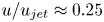 $u/u_{jet}\approx 0.25$. The underestimated peak velocity invariably results in gradients of smaller magnitude close to the centreline. Thus, the vorticity component
 $\omega _z=\partial v/\partial x - \partial u/\partial y$ is underestimated in this flow region.
This experimental error is typical of PIV measurements in high-gradient flows. However, it is limited to the region close to the potential core in the current study, i.e. to nozzle distances of approximately  $x\leq 6\,d$ or
 $x\leq 3\ \mathrm {mm}$ where other PIV-related shortcomings due to strong laser light reflections or particle buoyancy cannot be eliminated completely. The vortex rings studied here are only located in this region for very small non-dimensional formation times of about
 $t^*<5$. The main focus point of this article, however, is related to larger formation time scales as will be presented in the following.
Despite the mentioned insufficiencies concerning the experimental method, highly non-parallel flow can be attested. This is due to a rapid acceleration that ensues once the solenoid valve is opened. As a result, the circulation flux is increased and a strong transverse advection of fluid can be expected.
2.1.3. Computation of finite-time Lyapunov exponent fields
When referring to PIV data in the following, the phase-averaged velocity fields are regarded. No additional filter was applied to these. Using this database, time- and space-dependent three-dimensional finite-time Lyapunov exponent (FTLE) fields were computed. This flow diagnostic has gained considerable prominence in the field of fluid mechanics, enabling an understanding of transport mechanisms in dynamical systems. Indicating Lagrangian coherent structures (Haller Reference Haller2001), it can help uncover regions with a dominant influence on the properties of a given flow field. In the current article, material surfaces of exponential convergence are deduced, pointing to interfaces between vortex rings and the surrounding fluid and providing a degree of comparability with flow visualisation experiments. This is based on the fact that certain flow structures attract a greater amount of dye particles.
To compute three-dimensional FTLE fields, the domain spanned by PIV measurement planes and their mirrored counterparts was seeded with virtual passive tracer particles that are advected according to local velocity vectors using a fourth-order Runge–Kutta scheme. The initial distance between these tracers was  ${\rm \Delta} x = {\rm \Delta} y = {\rm \Delta} z = 0.3 \ \mathrm {mm}$, resulting in a structured grid of approximately
 $10^7$ points for which the FTLE was obtained. The advection was computed backward in time and the regarded finite-time interval was
 $\tau = T/2 = 10\ \mathrm {ms}$, ensuring particles interacted with a sufficient number of flow features as to reveal dominant material lines. However, the integration time was reduced for particles leaving the computation domain prematurely. Temporal interpolation based on a method introduced by Akima (Reference Akima1970) was applied, yielding time steps of
 ${\rm \Delta} t \approx 0.06 \ \mathrm {ms}$ for the FTLE computation. To acquire information regarding local velocity vectors at respective tracer locations, tricubic interpolation was employed.
2.2. Parallel starting jets generated with piston–cylinder arrangement
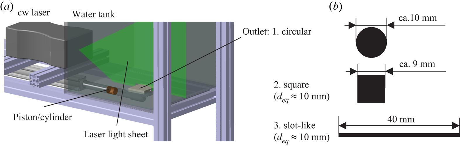
Experiments were also conducted inside a water tank to reproduce the parallel flow condition found in most previous studies. During these flow visualisations, a slot-like outlet similar to the one of the PJA was used to compare vortex rings produced by parallel and non-parallel planar starting jets. Furthermore, a circular outlet was employed to qualify the set-up by comparing the results to those previously obtained by Gharib et al. (Reference Gharib, Rambod and Shariff1998) and others while a square outlet represented the intermediate case.
Figure 4 shows a schematic depiction of the test rig used for flow visualisations as well as the dimensions of the three mentioned outlet geometries. Water resting in a brazen tube was impulsively accelerated by a piston mounted to a PC-controlled electric cylinder. In order to visualise the respective vortex structures, diluted fluorescein was added to the fluid through a circumferential slit of  $w = 0.3\ \mathrm {mm}$ width approximately
 ${\rm \Delta} s = 30\ \mathrm {mm}$ upstream of the nozzle. The dye particles were illuminated inside the respective symmetry planes of the outlets by means of a continuous-wave laser, and pictures were taken at a sampling rate of
 $f = 400\ \mathrm {Hz}$, capturing the process of vortex ring formation and propagation. The amount of added dye was controlled by adjusting the mounting height of the fluorescein reservoir. Since a compact test rig design was desired, the flow was redirected by
 $90^{\circ }$ between cylinder axis and outlet direction. As the subsequent tube was sufficiently long compared to the outlet dimensions, this had no apparent effect on the generated vortex rings that were generally symmetric and followed a vertical trajectory. It should be noted that the camera was rotated so that the propagation direction is from left to right in the images and movies presented in the following section.
Experimental set-up for flow visualisation.

The Reynolds number was kept constant at  $\mathit {Re} = (d_{h} u_{jet})/\nu = 1900$ for all of the outlet geometries. It was based on the hydraulic diameters of the outlets
 $d_{h}$ and the nominal jet velocity
 $u_{jet}$ deduced from the piston velocity and the ratio of tube to outlet area
 $A_{piston}/A_{out} \approx 6.4$. An impulsive velocity program with a piston acceleration of
 $|\mathrm {d}u/\mathrm {d}t| \approx 5\ \mathrm {m}\,\mathrm {s}^{-2}$ was applied and a rotary encoder was used to monitor the accurate piston advance.
3. Results
This section is structured as follows: first, we address the structure and motion of vortex rings associated with non-parallel planar starting jets, comparing them to steady planar jets and vortex rings produced by parallel starting jets discussed in the literature. Then, we analyse the vorticity flux and entrainment characteristics to identify characteristic formation time scales associated with maximum vortex ring circulation. This quantity is then reassessed by reducing the supply pressure, hence decreasing the degree of non-parallel flow for two further configurations. Finally, we discuss flow visualisations of planar starting jets in a water tank where the effect of over-pressure is negligible.
3.1. Appearance and propagation of vortex rings generated with PJA
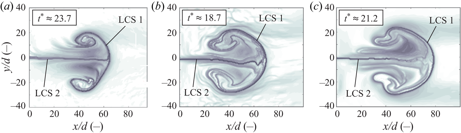
Figure 5 shows representative FTLE distributions associated with the vortex rings inside the symmetry plane at  $z=0\ \mathrm {mm}$. All three configurations are characterised by two dominant material surfaces, Lagrangian coherent structures (LCS) 1 and 2. The first marks the propagation front of the jets and reflects the interface between the vortex ring and ambient fluid. It indicates the regions of locally maximum shear stresses due to high velocity gradients. The trailing sides of the vortex rings are not closed by this material surface, however. Instead, it extends inside the vortex ring, mapping the radial entrainment through the leeward side of the rings. This radial entrainment is enhanced by the second significant material surface – a horizontal layer on the centreline. The vortex ring generated with the smallest stroke ratio is clearly smaller in size from a Lagrangian perspective. In particular, the axial extent is significantly smaller than for the other pulse widths. Comparing the two larger stroke ratios, vortex rings of similar dimensions are created, indicating that the stroke ratio only influences the structure of the vortex ring as long as a certain threshold is not surpassed.
Dominant material lines revealed by FTLE fields in  $xy$ symmetry plane for different stroke ratios. (a)
 $L/d_{eq} \approx 9$, (b)
 $L/d_{eq} \approx 15$ and (c)
 $L/d_{eq} \approx 48$.

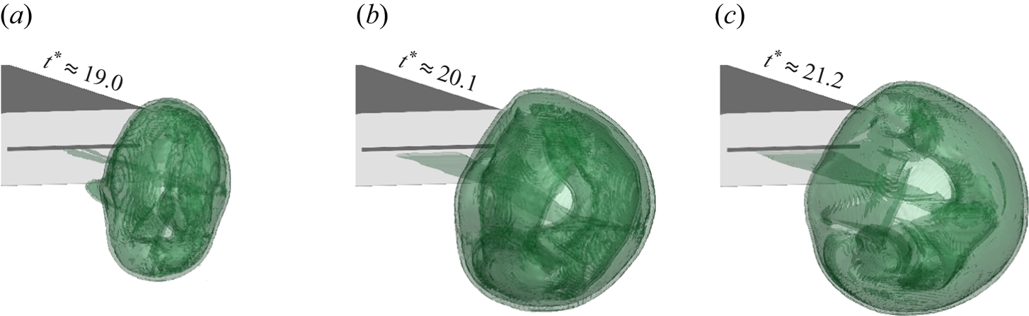
A further qualitative overview of the produced vortex rings is given in figure 6 where three-dimensional iso-contours in the FTLE distribution are shown for the three stroke ratios at  $t\approx 1.33\ \mathrm {ms}$. The respective non-dimensional formation times are indicated in the figure with the stroke ratio reflecting the nominal duration of jet emission. Hence, the jet emission has stopped for the small and medium stroke ratio whereas it is still ongoing for
 $L/d_{eq} \approx 48$ at the depicted time instances.
FTLE iso-contour of vortex rings associated with three investigated stroke ratios; slot-like jet outlet shown in the background for reference. (a)  $L/d_{eq} \approx 9$, (b)
 $L/d_{eq} \approx 15$ and (c)
 $L/d_{eq} \approx 48$.

Interestingly, all three vortex rings resemble spheroids characterised by a hole centred around the vortex core rotational axes. For the smallest stroke ratio  $L/d_{eq} \approx 9$, the vortex ring undergoes a rapid expansion in
 $y$ direction whereas the other dimension appears to be slightly contracted. There is only a very minor trailing structure visible. Compared to the larger stroke ratios, the streamwise propagation appears to be small which will be addressed subsequently. When a stroke ratio of
 $L/d_{eq} \approx 15$ is applied, the produced vortex ring is greater in size. The contraction close to the nozzle outlet is also less distinct, and a circular shape is apparent immediately as the vortex ring propagates with a greater mean velocity than for the lower stroke ratio. Even though a larger amount of fluid has been emitted for the greatest stroke ratio, there is no significant difference in terms of the vortex ring size compared to the medium stroke ratio. The distinct layer trailing the vortex ring corresponds to LCS 2 in figure 5 and points to a convergence of fluid towards the centreline of the jet.
In summary, the qualitative analysis has shown that the structure of all generated vortex rings is similar. However, the lowest stroke ratio yields a ring of significantly smaller dimensions while the diameter is almost equal for the other two configurations. We therefore assume that a characteristic formation time scale for vortex rings studied here lies in the range  $L/d_{eq}=9\text{--}15$. Before taking this hypothesis up in the next section, focus will be laid upon other characteristic properties of non-parallel planar starting jets.
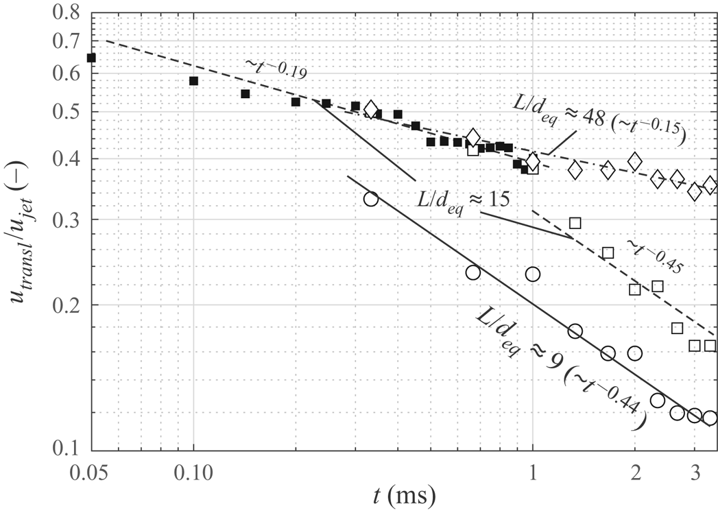
In figure 7, the propagation speed of the vortex rings  $u_{transl}$ is shown with reference to the nominal jet velocity at the outlet. The translational velocity was deduced by evaluating the location of the jet propagation front on the centreline, marked by a ridge in the FTLE field, for successive time instances.
Translational velocity of vortex rings associated with different stroke ratios.

For all stroke ratios, a distinct deviation between jet outlet velocity and vortex ring propagation speed can be noticed with the latter amounting to roughly one third of the initial velocity for  $L/d_{eq} \approx 9$ and one half for
 $L/d_{eq} \approx 15$ and
 $L/d_{eq} \approx 48$ at
 $t\approx 0.33\ \mathrm {ms}$. For the medium stroke ratio, further measurements were conducted with a finer temporal resolution. Marked by filled symbols, they indicate that the translational velocity close to the outlet is
 $u_{transl}\approx 0.65 u_{jet}$. Note that the axial velocity at
 $x\approx 2\ \mathrm {mm}$ measured with HWA is
 $0.8 u_{jet}$ (figure 2).
Interestingly, the propagation speed of the vortex rings is clearly affected during the ongoing emission of fluid. Both the medium and the highest stroke ratio exhibit vortex rings whose translational velocities roughly follow a  $-1/7$ power law decay initially. When the emission stops around
 $t = 1\ \mathrm {ms}$ for
 $L/d_{eq} \approx 15$, the propagation speed drops abruptly and a
 $t^{-0.45}$ power law decay is observed thereafter. A decay of the same order of magnitude can be observed for the smallest stroke ratio even though the normalised velocity is much smaller. As for the greatest stroke ratio, no velocity data are available after the emission process has stopped since the vortex ring has already left the measurement domain by that time.
In the work of Maxworthy (Reference Maxworthy1972), a  $-1$ power law decay is predicted for vortex rings generated with circular outlets. However, this was not validated empirically by Dabiri & Gharib (Reference Dabiri and Gharib2004) who reported an exponent of about
 $-1/3$. Compared to the latter value, the rate of velocity decay observed during the diffusive entrainment process in this study is larger. The discrepancy may be linked with the differences in the experiments, namely the outlet geometry and the significant over-pressure in the jet exit plane of the non-parallel jets studied here. It is conceivable that the initial transverse acceleration is accompanied by a smaller self-induced translational speed as noted by Afanasyev (Reference Afanasyev2006). In his study of vortex dipoles generated with two-dimensional outlets, a very slow propagation is reported for small formation times. Once a characteristic start-up time is reached, the vortex dipoles start translating with a larger, almost constant velocity of
 $u_{transl}\approx 0.5 u_{jet}$. A similar increase in velocity cannot be attested in our experiment as the propagation speed decreases monotonically. However, we also observed that the majority of jet expansion occurs at very small formation times as will be addressed in the following.
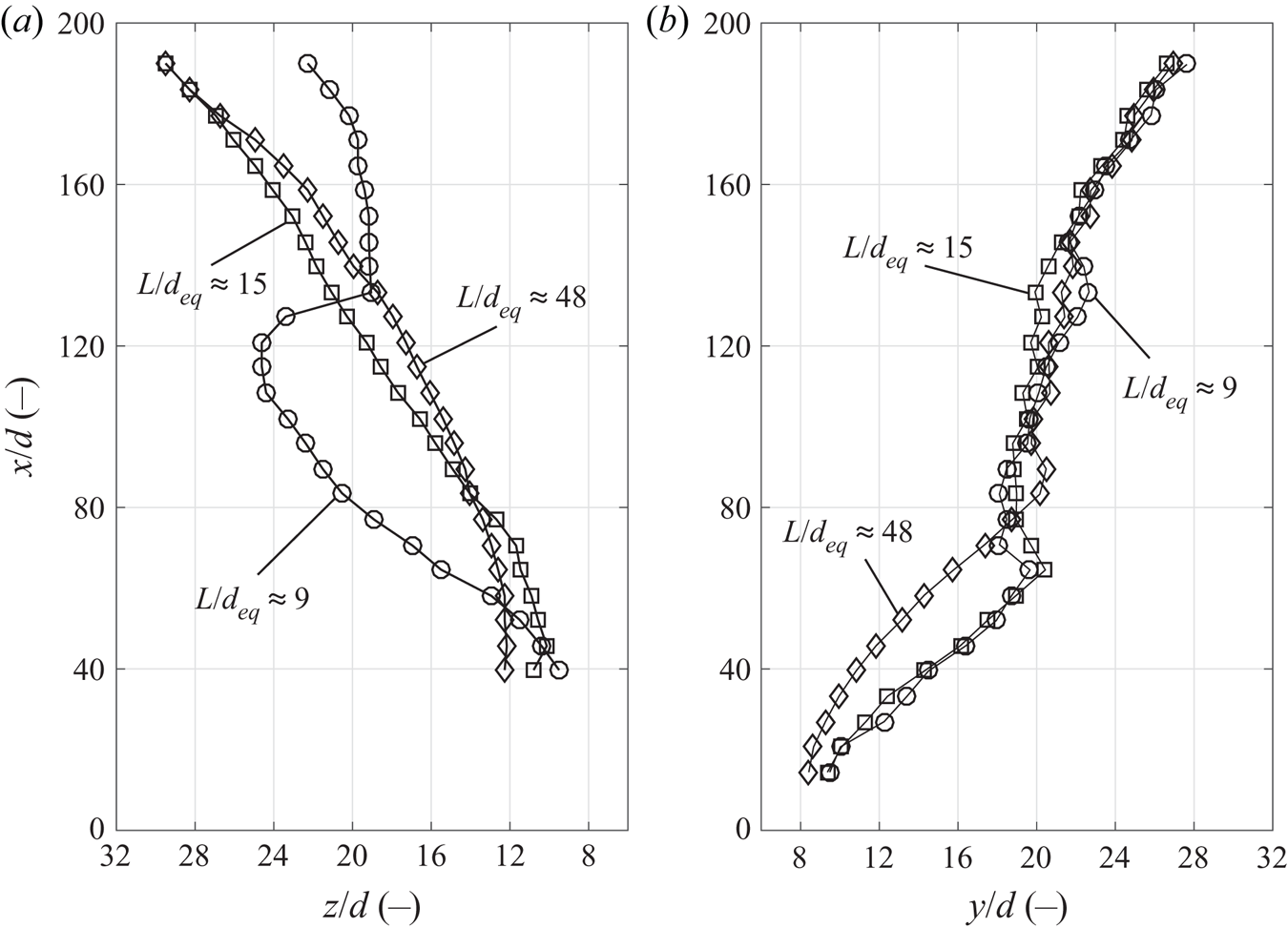
To estimate the spatial spreading rates of the non-parallel starting jets, the half-width in both transverse directions was calculated, i.e. the transverse distance where the mean axial velocity  $\bar {u}$ reaches half the mean centreline velocity. The mean value between positive and negative direction for
 $y_{1/2}$ is shown in figure 8 and the positive direction was chosen for
 $z_{1/2}$ – note that the velocity field was assumed symmetric in
 $z$ direction.
Jet half-width of non-parallel starting jets for different stroke ratios evaluated in both transverse directions.

Along the larger dimension of the slot-like outlet ( $z$ direction), the half-widths do not exceed the extent of the jet orifice initially with values of
 $z_{1/2} \approx 10 d$ found at an outlet distance of
 $x/d = 40$. For jets associated with the larger stroke ratios, an average expansion with a rate of roughly
 $s_z=(\mathrm {d}z_{1/2})/(\mathrm {d}x) = 0.12$ ensues. Interestingly, the smallest stroke ratio yields a significantly greater spatial expansion rate of
 $s_z\approx 0.18$ initially. Then, an abrupt reduction of the half-width by
 ${\rm \Delta} z_{1/2} \approx 4 d$ follows before a decreased spreading rate appears for the remainder of the observation domain. This behaviour is largely in agreement with the vortex ring revealed by the FTLE field in figure 6 which appears to be contracted along the
 $z$ direction at first.
As for the  $y$ direction, i.e. along the smaller dimension of the outlet, a rapid expansion can be observed up to an outlet distance of
 $x/d \approx 80$ with initial spreading rates of
 $s_y\approx 0.2$ for the two smaller stroke ratios and
 $s_y\approx 0.16$ for the largest stroke ratio respectively. Further downstream, a similar development of the half-width can be observed. After reaching a value of about
 $20 d$, only a minor expansion of the jet follows. Finally, spreading rates of
 $s_y\approx 0.11$ are found at
 $x/d>140$.
To summarise, the non-parallel starting jets studied here differ from the conventional steady planar jet in that they do not spread linearly at a constant rate. Instead, a rapid increase of the half-width along the smaller dimension of the outlet can be observed which may be caused by the transverse advection of fluid due to over-pressure during jet initiation. Further downstream, i.e. at larger formation times, a moderate growth rate is assumed. During both phases, the spreading rate is greater than for steady planar jets which is reported to be of the order of  $s_y\approx 0.1$, e.g. by Bradbury (Reference Bradbury1963), Knystautas (Reference Knystautas1964) or Gutmark & Wygnanski (Reference Gutmark and Wygnanski1976). This deviation is explained by the high degree of non-parallel flow characterising the starting jets in the current study.
3.2. Entrainment characteristics and development of vorticity fields
To estimate the entrainment of surrounding fluid, the growth of the vortex rings is evaluated. Their boundaries are, however, not well defined. Therefore, the reference frame is changed by superimposing the velocity field with the axial velocity found at the locations of maximum vorticity. This method was previously used by Dabiri & Gharib (Reference Dabiri and Gharib2004) and Sau & Mahesh (Reference Sau and Mahesh2007). The cross-sections of the resulting vortex bubbles inside both symmetry planes are displayed in figure 9.
Streamlines of velocity field superimposed with constant velocity found at location of maximum vorticity revealing vortex bubbles associated with different stroke ratios; ellipsoid fit used for computation of vortex bubble volume highlighted by dashed lines. (a,d,g)  $L/d_{eq} \approx 9$, (b,e,h)
 $L/d_{eq} \approx 15$ and (c,f,i)
 $L/d_{eq} \approx 48$.

At the first time step, the vortex rings exhibit a transverse extent 40 times the outlet width. This is consistent with the rapid initial jet spreading rate discussed previously. As a result, almost spherical vortex ring shapes characterised by thick cores are observed. Between the first and the second time step, a smaller increase in transversal growth can be noted in comparison. The smallest vortex ring ( $L/d_{eq} \approx 9$) shows a significant contraction in longitudinal direction as the respective dimension is only approximately half the length of the virtual emitted fluid column.
As indicated in the figure, an ellipsoid fit is used to approximate the volumes of the three vortex bubbles  $\varOmega _{B}$. This quantity is compared to the nominal volume of fluid
 $\varOmega _{N}$ that has been emitted over time to derive the entrainment fraction
 \begin{equation} \eta (t) = (\varOmega_{B} - \varOmega_{N})/\varOmega_{B}. \end{equation}
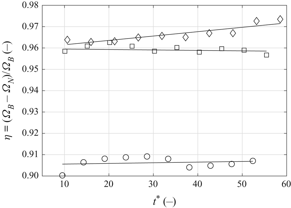
Compared to rings produced by parallel starting jets with typical entrainment fractions in the range of  $\eta = 0.3\text{--}0.4$ (Dabiri & Gharib Reference Dabiri and Gharib2004; Müller & Didden Reference Müller and Didden2004), the non-parallel starting jets appear to entrain significantly more ambient fluid (figure 10).
Entrainment fraction of vortex rings associated with different stroke ratios.

The calculated entrainment fractions are of the order of  $\eta \approx 0.90 \ldots 0.91$ (
 $L/d_{eq}\approx 9$) and
 $\eta \approx 0.96 \ldots 0.97$ (
 $L/d_{eq}=15,48$). In other words, the non-parallel jets entrain an amount of fluid approximately 10 or more than 20 times their own volume respectively. This is about an order of magnitude greater than for parallel starting jets. Considering the outlet geometry, the most drastic expansion of the vortex bubbles takes place along the smaller dimension. As indicated in figure 8, the vortex rings are almost axisymmetric for the two greater stroke ratios. This is reflected by the dimensions of the vortex bubbles that are of similar order in both transverse directions. Therefore, an almost uniformly distributed radial entrainment can be expected. It is also apparent that the early formation phase of the vortex rings is majorly responsible for this effect.
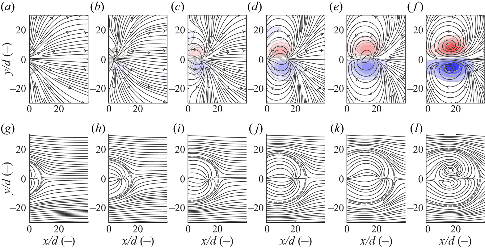
To investigate the early entrainment mechanisms in more detail, further measurements with a finer temporal resolution were conducted for the medium stroke ratio. Since the pressure and velocity information inside the nozzle exit plane were similar for the other stroke ratios during the initiation of fluid ejection, the results depicted in figure 11 are transferable to these configurations.
Vorticity fields and velocity field information during initiation of jet emission (a–f) and vortex bubbles at the same time instances (g–l). (a,g)  $t^{\ast} \approx 0$, (b,h)
 $t^{\ast} \approx 1.5$, (c,i)
 $t^{\ast} \approx 3.0$, (d,j)
 $t^{\ast} \approx 4.5$, (e,k)
 $t^{\ast} \approx 6.1$ and (f,l)
 $t^{\ast} \approx 7.6$.

Directly following the onset of fluid ejection ( $t^*\approx 0$), vorticity is advected in transverse direction and a vortex bubble extent of approximately
 $30\,d$ is found. For the next depicted time step (
 $t^*\approx 1.5$), the developing vortex ring cross-sections are aligned with the outward directed instantaneous streamlines as the transverse expansion continues. The vortex ring then continues to absorb vorticity but the growth of the vortex bubble in transverse direction is small in comparison to preceding time steps. Hence, the largest entrainment rate can be expected at small formation times up to
 $t^*\approx 5$, i.e. during the early part of fluid emission. This corresponds well with the initial pressure rise and the resulting development of velocity gradients shown in figures 2 and 3. It is worth noting that the vortex rings are still in close proximity to the outlet for this time span due to their low translational velocity similar to the experiments performed by Afanasyev (Reference Afanasyev2006).
This contrasts with investigations of compressible vortex rings reported by Arakeri et al. (Reference Arakeri, Das, Krothapalli and Lourenco2004) where the roll-up process is associated with much larger time scales than the initial pressure peak. It is therefore conceivable that the extent of non-parallel flow has a more distinct influence on the vortex ring formation in the current study.
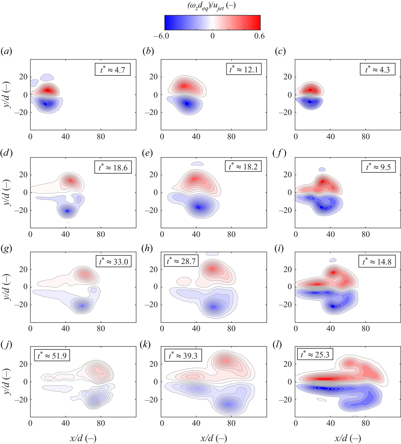
Next, we evaluate the subsequent vorticity fields generated with the three stroke ratios (figure 12).
History of vorticity fields for non-parallel planar starting jets generated with different stroke ratios. (a,d,g,j)  $L/d_{eq} \approx 9$, (b,e,h,k)
 $L/d_{eq} \approx 15$ and (c,f,i,j)
 $L/d_{eq} \approx 48$.

For the first displayed time step, the entire vorticity is located inside the vortex ring for all configurations. This is significant because the formation time scale introduced by Gharib et al. (Reference Gharib, Rambod and Shariff1998) is surpassed at that stage. Fluid is still emitted for all cases but no trailing jet structure is observed. During the second time step, the fluid ejection is only ongoing for the largest stroke ratio. It is interesting to note that small amounts of fluid are apparently detrained from the rear stagnation point for the smaller stroke ratios as minor trailing jets begin to develop. This process continues subsequently as the circulation of the vortex ring decreases. As for the largest stroke ratio, a trailing jet is formed already during jet emission and there is a distinct interaction between this flow feature and the vortex ring, causing the latter to become distinctly distorted by the last depicted time step.
Notably, once a trailing jet occurs, there is no clear separation between this jet and the vortex ring for any of the investigated stroke ratios, i.e. no pinch-off is observed as for circular or elliptic starting jets reported by Gharib et al. (Reference Gharib, Rambod and Shariff1998) and O'Farrell & Dabiri (Reference O'Farrell and Dabiri2014) respectively. This was ascertained previously by Pedrizzetti et al. (Reference Pedrizzetti, Domenichini and Tonti2010) and Afanasyev (Reference Afanasyev2006), studying vortex dipoles generated by planar starting jets. However, the nature of the interaction between trailing jet and vortex ring appears to be fundamentally different in the current study as the entire vorticity is absorbed by vortex rings initially before being detrained into a trailing jet. In previous studies of rectangular starting flows, it is the trailing jet that feeds the vortex ring during their interaction. We discuss this interesting observation in more detail below.
3.3. Development of circulation for  $L/d_{eq}\approx 15$

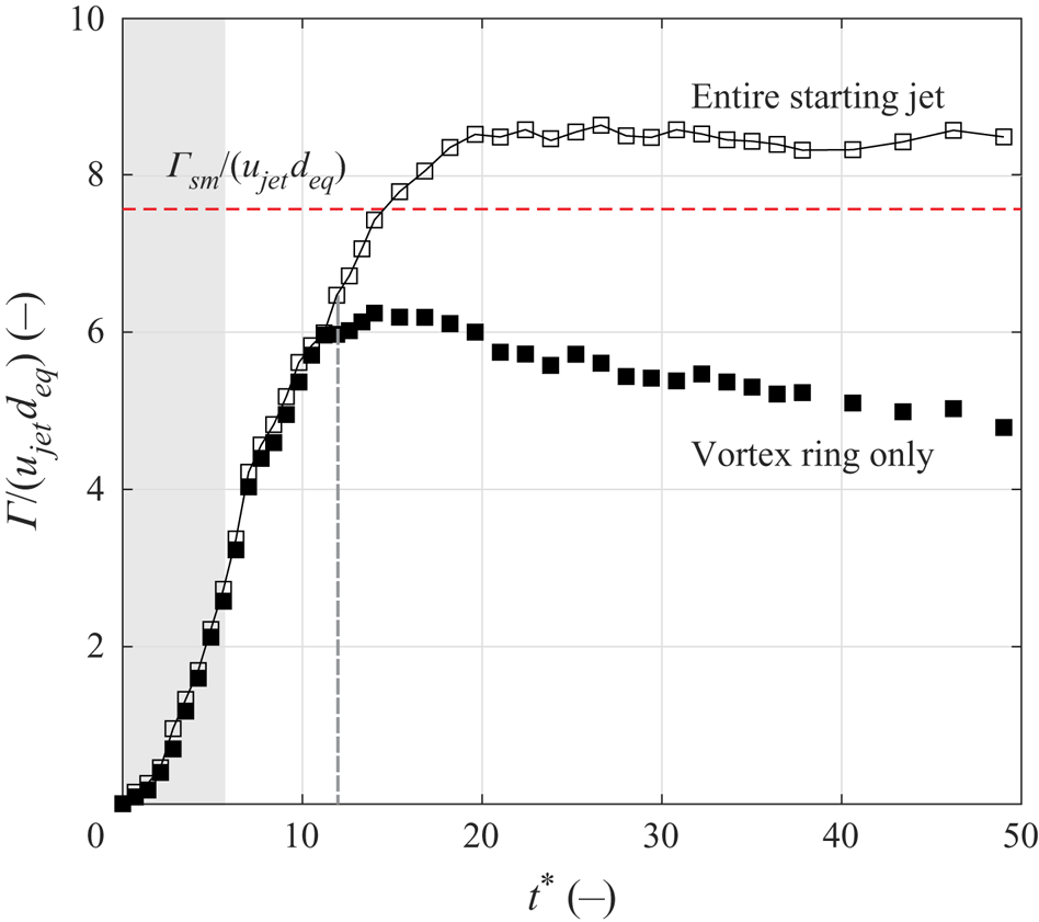
In the following, we focus on the time-resolved generation of circulation for the medium stroke ratio  $L/d_{eq}\approx 15$ (figure 13). Similar characteristics can be expected for the smallest stroke ratio based on the vorticity contour fields shown in figure 12, whereas a strong distortion occurs for the largest stroke ratio, complicating a clear distinction between flow structures, namely the leading vortex ring and the trailing jet.
Circulation associated with entire starting jet (open symbols) and vortex ring (closed symbols) over time for  $L/d_{eq}\approx 15$; total normalised circulation estimated by slug model highlighted by red horizontal; characteristic time scale associated with initiation of trailing jet highlighted by grey vertical line.

The circulation was obtained by integrating the vorticity field for the upper half-plane where  $y/d>0$ and inside the boundaries of a reasonable contour level which was defined to be
 $\omega _{z,{thresh}}= 200\ \mathrm {s}^{-1}$. In the presence of a trailing jet structure, the vorticity associated with the vortex ring and the trailing jet were not readily separable. As an intuitive measure, the defining ridge in the FTLE distribution was therefore used and extended on the trailing side to define the integration domain. Thus, the total induced circulation can be compared to the circulation associated with the vortex ring. The slug model prediction for the total circulation
 $\varGamma _{sm}=\frac {1}{2}t_{p}u_{jet}^2$ is highlighted by a red dashed line in figure 13.
The measured circulation is proportional to the formation time  $t^*$, and a maximum of
 $\varGamma /(u_{jet}d_{eq})\approx 8.6$ is reached at approximately
 $t^*\approx 20$, i.e. after the nominal end of the jet emission at
 $t^*=L/d_{eq}\approx 15$. This is consistent with velocity measurements shown in figure 2, indicating a decreasing axial velocity after this time instance. Note that the total circulation predicted by the slug model
 $\varGamma _{sm}/(u_{jet}d_{eq})\approx 7.6$ is exceeded by approximately 13 %. This is explained by the non-parallel flow condition enhancing the vorticity flux. However, a rapid increase in circulation can be expected for small formation times based on pressure measurements where an initial peak of large magnitude observed (figure 2). This is not reflected in PIV data that indicate a relatively small rate of change of circulation for
 $t^*<3$. There are two explanations. First, the axial jet velocity determining the vorticity flux is zero for
 $t^*\approx 0$ and only reaches a maximum after an initial acceleration phase. Second, and perhaps more importantly, the measured vorticity is underestimated as explained in § 2.1.2 and also observed in the vorticity fields for small formation times shown in figure 11. The corresponding region characterised by a smaller circulation flux is highlighted by a shaded background in figure 13. This experimental limitation does not affect our main conclusions found at larger formation times where the majority of vorticity is in greater distance to the outlet and the circulation predicted by the slug model is surpassed.
Initially, the entire vorticity is found inside the leading vortex ring indicated by almost equal values for the circulation of the entire starting jet (open symbols) and the vortex ring (closed symbols). This is in agreement with vorticity contour maps where no trailing jet is observed at that stage (figure 12). Around a non-dimensional formation time of  $t^*\approx 12$ (grey vertical), no further increase of the vortex ring circulation can be noted although fluid is still emitted. Instead, the vortex ring circulation stagnates before decreasing for the remainder of the observation time. Contrarily, the entire circulation remains at an almost constant level. This suggests that vorticity of the vortex ring is indeed continuously fed into a trailing jet as indicated in figure 12. This is in strong contrast to steady vortex rings studied by Gharib et al. (Reference Gharib, Rambod and Shariff1998) that exhibit almost constant circulation levels after pinch-off.
3.4. Influence of over-pressure effects
In the following, we examine the hypothesis that the specific behaviour discussed in the previous section is related to the degree of non-parallel flow driven by over-pressure in the nozzle exit plane. For this purpose, two further starting jet configurations were investigated where the supply pressure was varied at a fixed valve opening time of  $t_{p}=1\ \mathrm {ms}$, the same as for the medium stroke ratio of
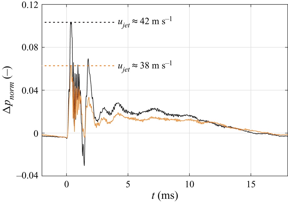
 $L/d_{eq}\approx 15$. As a result, the jet velocity, stroke ratio and maxima in the pressure signal decreased (figure 14).
Pressure signals for two configurations with varied supply pressure at  $(x,z)=(-2,0)\ \mathrm {mm}$ (compare with figure 2).

Recall that the normalised over-pressure maximum for the medium stroke ratio case so far was  ${\rm \Delta} p_{norm}\approx 1.2$ (see figure 2). In contrast, the initial peak for the further configurations is significantly decreased to
 ${\rm \Delta} p_{norm}\approx 0.1$ and
 ${\rm \Delta} p_{norm}\approx 0.06$ respectively. As a result, the over-pressure term contributing to the circulation generation (1.4) decreases.
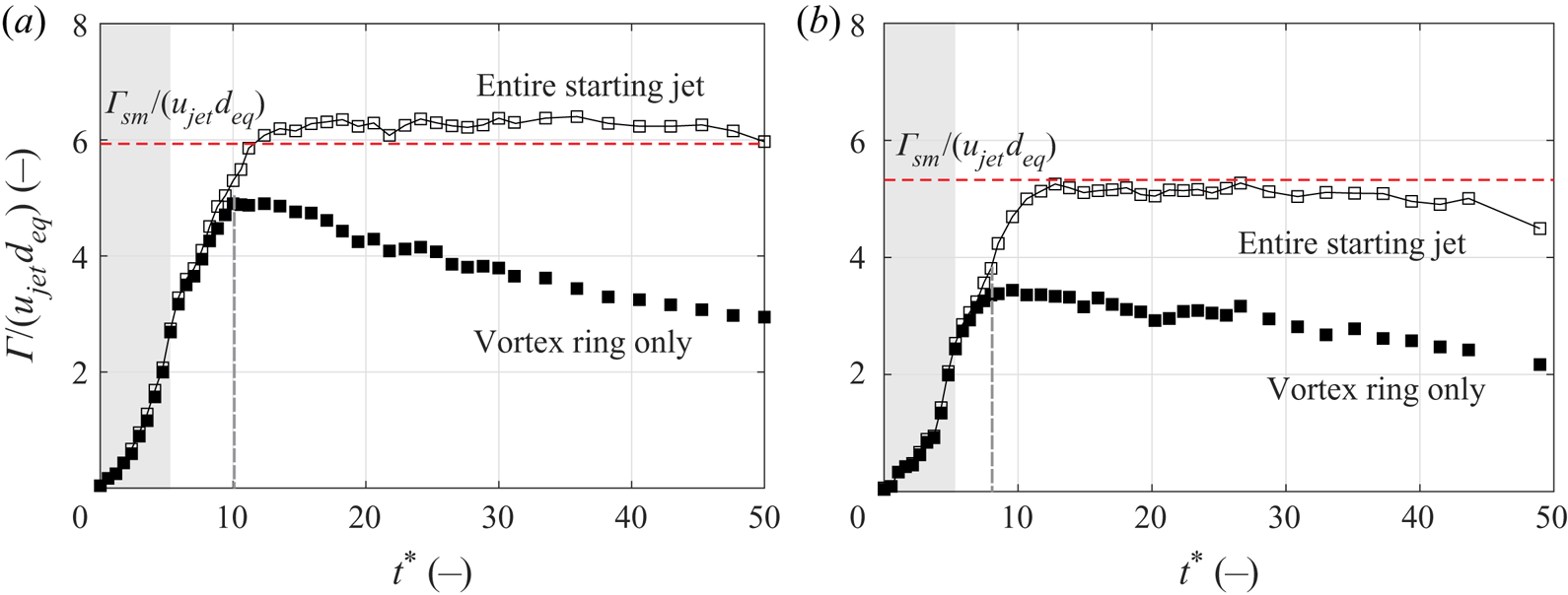
Analogous to the analysis in the previous section, the circulation was computed for these two configurations, see figure 15.
Produced circulation over time for cases of decreased over-pressure peak; distinction is made between vortex ring (closed symbols) and entire starting jet (open symbols). (a)  ${\rm \Delta} p_{pnorm,max}\approx 0.1$;
 $L/d_{eq} \approx 11.8$ and (b)
 ${\rm \Delta} p_{pnorm,max}\approx 0.06$;
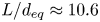 $L/d_{eq} \approx 10.6$.

The qualitative behaviour is very similar to that of starting jets associated with larger over-pressure as the vortex ring incorporates the entire circulation initially and sheds a trailing jet by detraining excessive vorticity after a maximum is reached. Crucially, the measured circulation maximum is only 8 % larger and of the order of the value predicted by the slug model for a reduced pressure peak of  ${\rm \Delta} p_{norm,max}\approx 0.1$ and
 ${\rm \Delta} p_{norm,max}\approx 0.06$ respectively. Recall that the circulation for the largest supply pressure was under-predicted by 13 %. This is in line with considerations given by Krueger (Reference Krueger2005), arguing that an increased magnitude in over-pressure extends the underprediction by the slug model.
Furthermore, the formation time corresponding to the initiation of a trailing jet is systematically decreased as values of  $t^*\approx 10$ and
 $t^*\approx 8$ are found for
 ${\rm \Delta} p_{norm}\approx 0.1$ and
 ${\rm \Delta} p_{norm}\approx 0.06$ respectively. As the characteristic formation time was of the order of
 $t^*\approx 12$ for the case of the largest over-pressure peak, the degree of non-parallel flow appears to have a significant influence on the maximum circulation the vortex rings can absorb.
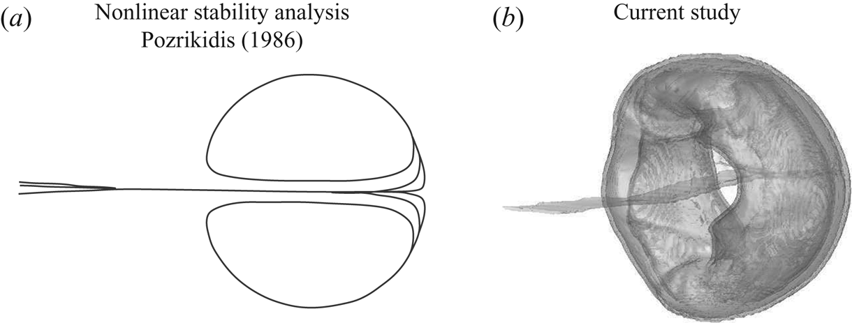
In establishing a formation number for circular parallel starting jets, Gharib et al. (Reference Gharib, Rambod and Shariff1998) reference the stability analysis conducted by Pozrikidis (Reference Pozrikidis1986) supporting their finding that excessive vorticity is detrained from the rear stagnation point of the vortex ring. As a consequence, it remains axis touching or returns to a steady axis-touching state. Clearly, this mechanism is not applicable to the vortex rings resulting from non-parallel starting jets studied here. They may be axis touching during the initial formation stage but the vorticity peaks subsequently move apart due to a rapid transverse expansion and an ongoing interaction with a trailing jet (figure 12). The resulting vortex shape resembles a flatter spheroid with a hole, an appearance also observed by Pozrikidis (Reference Pozrikidis1986) – and also by Moffatt & Moore (Reference Moffatt and Moore1978) – when the vortex ring is subjected to axisymmetric oblate perturbations. For this case, excessive vorticity is also accumulated in a ‘vortex tail’. This is in remarkable agreement with the vortex ring shapes observed in this study (figure 16). We therefore assume that the transverse acceleration of fluid, i.e. non-parallel flow, induces oblate perturbations whereas parallel or weakly non-parallel flow studied previously forces the vortex ring to become a prolate spheroid.
(a) Vortex ring with small oblate perturbation (based on depiction by Pozrikidis Reference Pozrikidis1986). (b) FTLE iso-surface of vortex ring generated with non-parallel planar starting jet at  $L/d_{eq}\approx 15$.

Given the larger diameter of the oblate vortex rings that is increased due to the lateral growth caused by over-pressure, the impulse  $I=I(r^2)$ is larger than for prolate vortex rings. In addition, the circulation is increased compared to vortex rings generated with parallel starting jets as addressed previously. This suggests that the dimensionless energy
 $\alpha$ (1.3) is smaller in comparison as the product of circulation and impulse
 $\varGamma ^{3/2}I^{1/2}$ is increased to a greater extent than the kinetic energy
 $E=E(r)$. This estimation is supported by models for the invariants of motion for non-parallel starting jets supplied by Krieg & Mohseni (Reference Krieg and Mohseni2013).
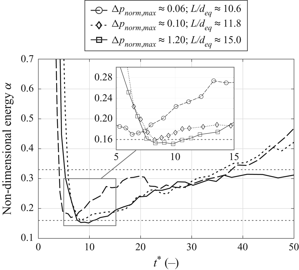
The non-dimensional energies of the studied vortex rings generated with varied supply pressure are shown in figure 17. The invariants of motion were obtained by area integration inside the  $xy$ symmetry plane based on phase-locked PIV measurements
 \begin{equation} \varGamma = \int_{0}^{x_\infty}\!\!\int_{0}^{y_\infty} \omega\, \mathrm{d}y \,\mathrm{d}x; \enspace I = \varrho {\rm \pi} \int_{0}^{x_\infty}\!\!\int_{0}^{y_\infty} \omega y^2 \, \mathrm{d}y \,\mathrm{d}x; \enspace E = \varrho {\rm \pi} \int_{0}^{x_\infty}\!\!\int_{0}^{y_\infty} (u^2 + v^2)\, \mathrm{d}y\, \mathrm{d}x. \end{equation}
Dimensionless energies of vortex rings generated with different supply pressure; horizontals for limiting energy  $\alpha _{lim}=0.33$ found by Gharib et al. (Reference Gharib, Rambod and Shariff1998) as well as theoretical value for Hill's spherical vortex
 $\alpha =0.16$ shown for reference.

During the initial formation process, the non-dimensional energy drops as thicker vortex ring cores are rapidly generated. Slightly preceding the respective moments where maximum circulation is reached, the energy falls below the limiting value of  $\alpha _{lim}=0.33$ reported by Gharib et al. (Reference Gharib, Rambod and Shariff1998) around a formation time of
 $t^*\approx 5$. Subsequently, minima in vortex ring energy are reached. The configuration of largest over-pressure yields the smallest vortex ring energy of
 $\alpha \approx 0.15$, i.e. the thickest ring core. In comparison, slightly larger minimum energies of
 $\alpha \approx 0.16$ and
 $\alpha \approx 0.17$ are found for the other configurations. While these differences are relatively small, it is important to note that there is a clear tendency as vortex ring energies increase with reduced peaks in over-pressure. In other words, a larger over-pressure level yields a thicker vortex ring core. It should be noted that the limiting member of the Norbury–Fraenkel family of vortex rings is characterised by a non-dimensional energy of
 $\alpha \approx 0.16$. All configurations reach values of this order before starting to increase, indicating that this is in fact the limiting energy applicable to the current set-up. However, no constant value is assumed afterwards as was observed for the steady vortex rings investigated by Gharib et al. (Reference Gharib, Rambod and Shariff1998). This may be due to an ongoing interaction between the vortex ring and the trailing jet.
Overall, the degree of non-parallel flow associated with a varied magnitude in over-pressure has a systematic effect on vortex ring properties. First, the circulation flux is enhanced. Second, the moment when vortex rings start to shed vorticity is shifted to larger formation times which results in larger circulation maxima when the supply pressure is increased. And third, while vortex rings studied here have similar minimum non-dimensional energies, there is a trend in that greater over-pressure causes vortex rings with thicker cores.
3.5. Parallel planar starting jets
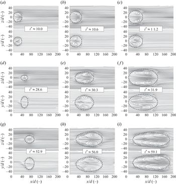
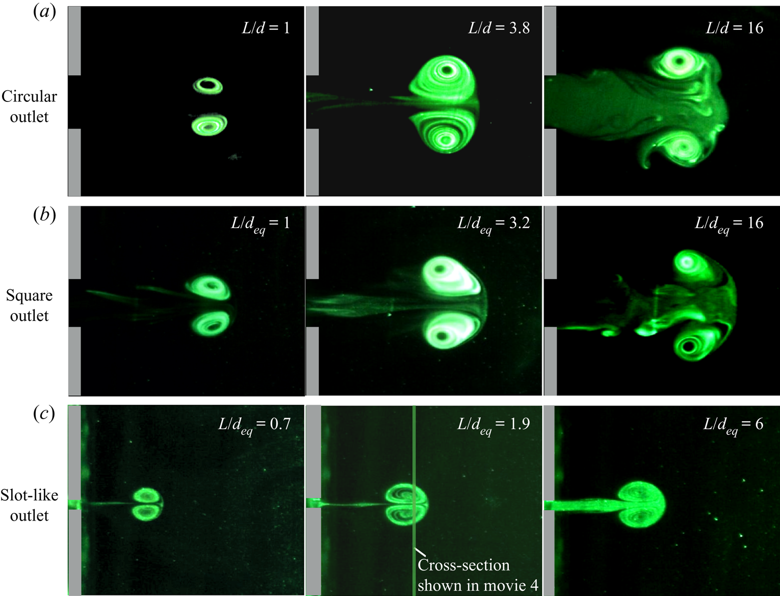
Finally, we shall validate that the effects discussed above are indeed caused by non-parallel flow and not by the specific outlet geometry that also differs from those usually studied in the literature. Using the experimental apparatus shown in figure 4, vortex rings were generated by emitting fluid columns in an impulsive fashion through outlets of different geometries into a water tank. Generating parallel starting jets, this set-up was comparable to the ones used by Gharib et al. (Reference Gharib, Rambod and Shariff1998) and others. The length of the fluid column was varied by changing the travel length of the cylinder, resulting in a large number of investigated stroke ratios. Figure 18 shows a selection of images that are relevant to the purpose of this discussion. Movies of the flow visualisations are provided with the supplementary material available at https://doi.org/10.1017/jfm.2020.637. Movie 1 contains recordings for the circular, movie 2 for the square and movie 3 for the slot-like outlet.
Flow visualisation of vortex rings generated with different outlet geometries; the central column shows vortex structures associated with characteristic formation time scale (Gharib et al. Reference Gharib, Rambod and Shariff1998) yielding a vortex ring of maximum size without trailing jet whereas stroke ratio was set to lower and higher values for the pictures shown in left and right columns, respectively.

As for the circular starting jet, an individual vortex ring can be observed at small stroke ratios, e.g.  $L/d = 1$. When increasing the stroke ratio, larger vortex rings are produced and the limiting case, i.e. the formation number, is in the region of
 $L/d = 3.8$ in our experiment. Hence, the results obtained with the current experiment are in good agreement with the formation number for parallel circular starting jets
 $L/d \approx 3.6\ldots 4.5$ established by Gharib et al. (Reference Gharib, Rambod and Shariff1998).
Studying parallel starting jets emitted from a square orifice, small stroke ratios again result in individual vortex rings. The formation number for this scenario  $L/d_{eq} \approx 3.2$ is slightly smaller than for the circular outlet. Furthermore, the vortex rings appear to be less stable and a sooner breakdown can be observed (movie 2).
The planar starting jets shown in figure 18(c) exhibit a comparable behaviour as the other parallel jets when the stroke ratio is varied. In contrast to the non-parallel starting jets addressed above, however, no circular vortex ring is produced. Instead, two parallel vortex tubes can be seen in movie 4 provided with the supplementary material showing the vortex dipoles generated with a stroke ratio of  $L/d_{eq} \approx 1.9$ travel through the illuminated cross section at
 $x=20\ \mathrm {mm}$ highlighted in figure 18. This is in agreement with other studies of parallel planar starting jets, e.g. by Afanasyev (Reference Afanasyev2006) or Das et al. (Reference Das, Govardhan and Arakeri2013). Accordingly, the transverse dimension of vortex dipoles is only four to five times the outlet width whereas a diameter of
 $40\,d$ was observed for the vortex rings associated with non-parallel starting jets. The vortex tubes in our experiment reach a maximum diameter for
 $L/d_{eq} \approx 1.9$, i.e. half the value found for the circular outlet. This can be explained by the fact that the outlet width decreases for greater outlet aspect ratios at a given equivalent diameter
 $d_{eq}$. As the vortex dimension is proportional to the outlet width for parallel jets, this leads to a smaller formation number.
To summarise, the flow visualisations indicate that the specific behaviour observed for the vortex rings generated with pressurised air is indeed linked with the non-parallel flow condition and not with the slit-shaped outlet geometry.
4. Conclusions
The focus point of this study was starting jets generated with a device typically employed in AFC applications, ejecting defined amounts of compressed air as a mechanical valve is periodically opened for relatively small pulse durations. This specific flow configuration is characterised by two major differences compared to starting jets addressed in the majority of previous studies. First, the outlet geometry is not circular but slit shaped and has an aspect ratio of  $l/d=40$. Second, the non-dimensional over-pressure during jet initiation is approximately an order of magnitude larger than for starting jets produced with a classical piston–cylinder set-up reported by Krieg & Mohseni (Reference Krieg and Mohseni2013) for instance. Therefore, the influence of over-pressure during the early vortex ring formation phase is much more distinct in the current study, initiating a strong transverse acceleration of fluid, i.e. highly non-parallel flow.
Two major objectives were addressed in investigating this flow: to (i) reveal the properties relevant to AFC applications and compare them to previous studies of starting flows, (ii) examine the hypothesis that the concept of a universal formation time scale applicable to parallel circular starting jets introduced by Gharib et al. (Reference Gharib, Rambod and Shariff1998) can be extended to this particular flow configuration.
A significant transverse advection of fluid was observed close to the jet outlet. This was reflected in initial spreading rates up to  $s_y\approx 0.2$ along the smaller dimension of the outlet, i.e. approximately twice the value for steady planar jets reported by Bradbury (Reference Bradbury1963) or Gutmark & Wygnanski (Reference Gutmark and Wygnanski1976). Given these large spreading rates, almost spherical vortex rings with a diameter approximately 40 times the slot width were found despite the high aspect ratio outlet geometry. This is explained by an enhanced vorticity flux previously observed for impulsively initiated starting jets, e.g. by Didden (Reference Didden1979) or Krieg & Mohseni (Reference Krieg and Mohseni2013) and is directly relatable to over-pressure inside the jet exit plane associated with the rapid acceleration of fluid as noted by Krueger (Reference Krueger2005). In the current study, the over-pressure occurs for a long duration relative to the formation process of up to
 $t^*\approx 5$. The produced vortex rings are located close to the outlet for this duration, directly absorbing the enhanced vorticity flux which leads to a very large expansion of vortex rings for small formation times. This contrasts with experiments of compressible vortex rings generated with an open shock tube performed by Arakeri et al. (Reference Arakeri, Das, Krothapalli and Lourenco2004) where a similar over-pressure peak occurs but in that case, it is associated with much smaller time scales than the vortex sheet roll-up process. In the current study, the propagation during the initial pressure rise is smaller which may be ascribed to the outlet geometry as similar observations regarding the competing effects of expansion and translation were made by Afanasyev (Reference Afanasyev2006), also studying two-dimensional starting jets. However, the over-pressure in his experiment was assumedly negligible. Hence, only a roll-up of parallel vortex tubes was observed, agreeing well with flow visualisations inside a water tank conducted in the current study where a transverse dimension of vortex dipoles less than 5 outlet widths is noted.
The rapid expansion is associated with very large entrainment rates up to  $\eta \approx 0.97$, indicating that the starting jets are capable of entraining an amount of fluid about 20 times their own volume. Typical entrainment rates for parallel starting jets, on the other hand, are in the range
 $\eta =0.3\text{--}0.4$ (Dabiri & Gharib Reference Dabiri and Gharib2004).
Considerable proof has also been presented that the applied over-pressure has a drastic effect on characteristic time scales applicable to the starting jets in the current article. Vortex rings were shown to gather circulation beyond the universal formation time  $t^*\approx 4$ introduced by Gharib et al. (Reference Gharib, Rambod and Shariff1998). Depending on the magnitude of over-pressure, circulation was accumulated inside the leading vortex ring up to
 $t^*\approx 8$ (
 ${\rm \Delta} p_{norm,max}\approx 0.06$) or even
 $t^*\approx 12$ (
 ${\rm \Delta} p_{norm,max}\approx 1.2$). Considering that the circulation flux was also increased by the extent of over-pressure, larger maxima in normalised vortex ring circulation were observed when the supply pressure was increased. Thus, the circulation predicted by the slug model was exceeded by as much as 13 %.
In contrast to previous studies of circular or elliptic starting jets reported by Gharib et al. (Reference Gharib, Rambod and Shariff1998) and O'Farrell & Dabiri (Reference O'Farrell and Dabiri2014), no clear separation between the leading vortex ring and a trailing jet was observed. This is consistent with investigations of two-dimensional starting jets summarised by Pedrizzetti et al. (Reference Pedrizzetti, Domenichini and Tonti2010). Afanasyev (Reference Afanasyev2006) observed that an ongoing interaction between the trailing jet and the vortex ring causes the latter to absorb vorticity beyond the characteristic formation time of  $t^*\approx 4$. However, a fundamentally different mechanism was noted in the current study as a trailing jet only developed after a pressure-dependent maximum in vortex ring circulation was achieved. This is enabled by a persistent shedding of vorticity as the vortex ring reaches states of ever thinner cores. We attribute this to an overshoot in vortex ring energy, roughly coinciding with the time instance of maximum circulation. Here, an energy close to or even below the characteristic value of
 $\alpha \approx 0.16$ attributed to Hill's spherical vortex was measured. While the differences in non-dimensional energy were relatively small when the magnitude in over-pressure was varied, we still observed a tendency of larger over-pressure yielding a thicker vortex ring core. Following this overshoot in non-dimensional energy, vorticity is detrained. It is worth noting that this was also observed by Moffatt & Moore (Reference Moffatt and Moore1978) and Pozrikidis (Reference Pozrikidis1986), investigating perturbations applied to Hill's spherical vortex. The current work may therefore in some ways be seen as the experimental pendant to previous stability analyses. Furthermore, Gharib et al. (Reference Gharib, Rambod and Shariff1998) reported a similar overshoot. However, this was not explicitly achieved by the magnitude in over-pressure but by the merging of two vortex rings. Then, a larger vortex ring develops before shedding vorticity and reaching a stable state associated with a limiting non-dimensional energy of
 $\alpha _{lim} \approx 0.33$ that was specific to their apparatus. Such a constant energy level was not observed in the current study as the vortex ring energy continuously increased inside the observation domain. This may be explained by the absence of a pinch-off and the unsteady character of interaction between vortex ring and trailing jet.
Therefore, the concept of a characteristic formation number introduced by Gharib et al. (Reference Gharib, Rambod and Shariff1998) cannot be extended to the specific flow configuration investigated in the current article. No pinch-off between vortex ring and trailing jet is observed, and the formation time associated with maximum circulation can be changed by varied boundary conditions, namely the magnitude of over-pressure.
Nonetheless, our findings have some implications for AFC applications where vortex rings are generated with a method similar to the one used in this study.
First, the knowledge regarding the reported formation mechanisms enables an efficiency optimisation. Considering that the mixing effectivity is mainly determined by the leading vortex ring associated with a starting jet, the pulse width for a given outlet velocity can be adjusted so that this structure is exclusively generated. Beyond a certain pulse width, a trailing structure is not only indirectly formed by vorticity shed from the vortex ring but directly from ejected fluid not absorbed by the vortex ring. This was observed for the largest investigated stroke ratio of  $L/d_{eq}\approx 48$. The trailing jet is expected to have properties similar to steady jets with shear rates well below those inside the vortex ring (Choutapalli et al. Reference Choutapalli, Krothapalli and Arakeri2009). Thus, jet modulation with the pressure-dependent optimal pulse width can help to reduce the mass flow consumption.
Second, the degree of non-parallel flow was shown to correlate with the circulation of vortex rings. An enhancement of this quantity is typically desired in AFC applications. Hence, a pressure increase may be recommended. However, the supply pressure is usually limited in technical applications. Therefore, future studies must address the proportionality between over-pressure and entrainment of ambient fluid in more detail. In this regard, it is of particular interest if the increase in mixing rate is continuous or if it is suddenly enhanced when a vortex ring of different shape, i.e. with an oblate form, is produced beyond a certain magnitude of over-pressure.
Furthermore, it was shown that the early vortex ring formation phase of  $t^*<5$ is majorly responsible for the rapid jet expansion. This phase should be addressed in more detail in future numerical investigations as it was affected by experimental shortcomings in the current study due to the small outlet dimensions typical of AFC devices.
Acknowledgements
The authors gratefully acknowledge financial support from the Deutsche Forschungsgemeinschaft (DFG, German Research Foundation) – under project number 426637148.
Declaration of interests
The authors report no conflict of interest.
Supplementary movies
Supplementary movies are available at https://doi.org/10.1017/jfm.2020.637.