



Nomenclature
-
 $\bar c$
-
mean aerodynamic chord
-
$D,Y,L\;$
-
aerodynamic forces (drag, side force, lift)
-
$D$
-
propeller diameter
-
${\bf{F}}\;$
-
force vector
-
${\bf{f}}$
-
propellers direction vector
-
${\bf{g}}$
-
gravity vector
-
${\bf{H}}$
-
angular momentum vector
-
$h$
-
altitude
-
$\tilde I$
-
inertia tensor
-
$j$
-
cost function
-
$K$
-
control allocation matrix
-
$k$
-
control conversion constant, PID controller gain, propeller linearised thrust and torque coefficient
-
$\bar L,M,N$
-
aerodynamic moments (in roll, pitch, yaw)
-
$l$
-
fuselage length
-
$M$
-
total mass
-
$P,Q,R$
-
angular velocities
-
$R$
-
rotation matrix
-
${\bf{r}}$
-
position vector
-
$S$
-
wing or canard planform area, body-to-wind axes rotation matrix
-
${\bf{T}}$
-
torque vector
-
$T,Q$
-
propeller thrust and torque
-
$t$
-
time
-
${\bf{U}},U$
-
control input
-
$U,V,W$
-
linear velocities
-
${V_T}$
-
flight speed
-
${\bf{v}}$
-
velocity vector
-
$x,y,z$
-
position coordinates


Greek Symbol
-
$\alpha $
-
aircraft angle-of-attack
-
$\beta $
-
aircraft sideslip angle
-
$\delta $
-
mounting angle
-
$\varepsilon $
-
downwash angle
-
$\varepsilon $
-
transition stability cost function
-
$\lambda $
-
propeller rotation direction (1 clockwise or -1 counterclockwise)
-
$\rho $
-
air density
-
$\tau $
-
first-order dynamic system time constant
-
$\upsilon $
-
propeller tilt angle
-
$\phi, \theta, \psi $
-
Euler angles
-
${\rm{\Omega }}$
-
angular velocity cross product in matrix form
-
$\omega $
-
angular velocity vector


Subscripts
-
$aero$
-
aerodynamic
-
$B$
-
body reference frame
-
$des$
-
desired
-
$E$
-
Earth fixed inertial reference frame
-
$e$
-
exposed aerodynamic surface, or equilibrium condition
-
$j$
-
rotor index
-
$pos$
-
position
-
$prop$
-
propulsive
-
$Q$
-
propeller torque coefficient
-
$R$
-
rotor
- sp
-
setpoint
-
$T$
-
propeller thrust coefficient
-
$th$
-
threshold
-
$vel$
-
velocity
-
$w,c$
-
wing and canard
-
${\omega _R}$
-
propeller angular velocity


1.0 Introduction
The lifting-wing multirotor is a new type of UAV configuration under study with some initiatives and prototypes to better understand this configuration’s performance and capabilities. The lifting-wing multirotor is a multirotor UAV with a short wing installed at a specific mounting angle [Reference Xiao, Meng, Dai, Zhang and Quan1]; however, in this study, it has not only a short wing but also a canard at the front of the vehicle.
Some prototypes of this UAV configuration are under development and testing, being that in Fig. 1 are shown four examples: (a) the LAQ Drone of the University of Tokyo [Reference Staub, Tsukada, Inoue, Raabe and Tsuchiya2, Reference Staub, Premeaux, Tsukada, Inoue, Raabe and Tsuchiya3]; (b) the VertiKUL 2 of the University of Leuven [Reference Theys, Vos and Schutter4]; (c) the RflyLW2 of the Beihang University [Reference Xiao, Meng, Dai, Zhang and Quan1, Reference Zhang, Tan, Song and Quan5] and (d) the Amazon Prime Air delivery drone [Reference Palmer6]. As can be seen, this hybrid UAV configuration is notable for a set of motors and propellers, of at least four, for takeoff, landing and hovering, in addition to the aerodynamic surfaces, which provide lift while the vehicle performs forward flight.
Examples of lifting-wing multicopters.

The flight principle of this configuration is to gradually tilt the full body of the multicopter in a negative pitch angle manner to direct the thrust vector of the propellers partially forward so that the UAV accelerates and performs forward flight. As the UAV gains forward speed, the aerodynamic surfaces, that is, the wing and canard, will generate lift so that the power required by the motors is reduced. This way, the onboard batteries’ power consumption is reduced, which enables longer ranges and autonomy. Such improvement in performance was verified through experiments for a lifting-wing concept in Ref. [Reference Xiao, Meng, Dai, Zhang and Quan1] with a reduction of
 $50.14$
% in required power at cruise speed at 15 m/s compared to required power to hover for the same vehicle without the wing. Moreover, in Ref. [Reference Staub, Premeaux, Tsukada, Inoue, Raabe and Tsuchiya3], the authors tested a lift-augmented quadcopter, which was a modified hexacopter, by removing the left and right motors and propellers and using the rotor arms as wing spars [Reference Staub, Tsukada, Inoue, Raabe and Tsuchiya2]. The wind tunnel tests showed a reduction in minimum power consumption at cruise speed (14–16 m/s) up to
 $57.8$
% over the original hexacopter. However, despite the gains in cruise flight, a reduction in performance in hovering conditions is expected, mainly due to the additional weight of the aerodynamic surfaces.
Therefore, the applications of this type of UAV would be mainly in situations where gains in operating efficiency of current operations of multicopters in flights that need to cover large areas at relatively low speeds would bring great advantages to operators. Such applications would be parcel delivery [Reference Frachtenberg7], photogrammetry for mapping and 3D modeling [Reference Remondino, Barazzetti, Nex, Scaioni and Sarazzi8], activities related to precision farming like soil health scans, assistance in irrigation, fertilizers application, crops health monitoring and pesticide spraying [Reference Hafeez, Husain, Singh, Chauhan, Khan, Kumar, Chauhan and Soni9], the monitoring, measurements and flux estimates of greenhouse gases concentration in the atmosphere [Reference Kunz, Lavrič, Gasche, Gerbig, Grant, Koch, Schumacher, Wolf and Zeeman10, Reference Liu, Paris, Vrekoussis, Antoniou, Constantinides, Desservettaz, Keleshis, Laurent, Leonidou, Philippon, Vouterakos, Quéhé, Bousquet and Sciare11] and environmental chemical sensing applications [Reference Burgués and Marco12].
The lifting-wing multicopter is a type of vertical take-off and landing (VTOL) UAV with a relatively simple and smooth transition manoeuver, compared to the complex flight transition control algorithms of tilt-rotor [Reference Liu, He, Yang and Han13], tilt-wing and tail-sitter configurations. Tilt-rotor and tilt-wing configurations have a complex transition from hover to cruise flight; the acceleration and deceleration of the aircraft must be accompanied by a complex system of synchronisation of flight speed, tilt angles and rotation speed of the rotors, the inclination of the aerodynamic surfaces, and controller gains, to deal with the changing dynamics of the system along with flow separation and post-stall aerofoil behaviour, propeller-wing slipstream interaction, the effect of flaps and control surfaces, induced drag and the influence of propeller swirl, the effect of high sideslip angles [Reference May, Milz and Looye14], gyroscopic moments and shifting of the centre of gravity [Reference Daud Filho and Belo15]. The tail-sitter has no tilting wing or tilting rotor mechanisms, but it has to rotate the full body 90
 ${{\rm{\;}}^ \circ }$
to perform a full transition manoeuver from hover to cruise flight and back from cruise to hover and landing. In Ref. [Reference Jung and Shim16], the authors discuss [so]me strategies to perform such manoeuvers like the stall and tumble procedure, which is risky where the tail sitter aircraft is tossed from the domain of the hover controller in the hope that it will be captured by the cruise controller, which usually is linear and has a limited domain of attraction; an optimal transition trajectory that minimises the transition time, altitude loss and control variations, which still includes a descending segment, although the altitude loss is not as steep as with the stall-tumble, and the continuous ascending trajectory, in which the flight path is always gaining altitude while transitioning in a smooth manner from a near-hover vertical flight to a horizontal cruise flight.
Moreover, most VTOL UAV uses the concept of the transition trajectory, or transition corridor, to evaluate the possibility and viability of a given aircraft concept to perform the transition flight from hover to cruise by checking whether there are possible equilibrium points between these flight states at intermediate speeds, which despite not guaranteeing that the transition between the equilibrium points will be controllable, this is an indication that the transition is possible and smooth [Reference Liu, He, Yang and Han13, Reference Daud Filho and Belo15, Reference Milz and Looye17]. The transition corridor is usually computed based on static trim analysis, which results in a conservative estimate that neglects the dynamic manoeuverability of the aircraft. In Ref. [Reference May, Milz and Looye18], the authors addressed the problem of calculating the transition corridor of a tilt-wing aircraft by transcribing it as a nonlinear programming problem (NLP), where the system dynamics are considered in the form of constraints in the NLP formulation. This way, the transition can be optimised for objectives of interest, such as minimising transition time, transition distance, terminal altitude, offset from reference trajectory or energy consumed.
Most multicopters use flight control system architectures involving a sequence of controllers or cascaded control architecture, most notably position control, velocity control, attitude control and angular rate control, where each is typically Proportional-Integral-Derivative (PID) controllers [Reference Mellinger19, Reference Quan20], so that the output of a controller is a desired input for the next. Eventually, the resulting output is the desired thrust and moments to be produced by the propulsors. Lastly, control allocation calculates the desired propellers’ angular speeds, which must result in the desired thrust and moments.
Furthermore, to deal with the transition manoeuver of VTOL UAV, some techniques have been proposed, such as PID with gain scheduling to deal with the varying dynamics characteristics along the transition manoeuver [Reference Liu, He, Yang and Han13], gain-scheduled linear quadratic regulator (LQR) controller where the dynamic equations of motion are linearised at the trim points along the flight transition corridor so that optimal control theory can be used to compute the gain matrices [Reference Daud Filho and Belo15, Reference Ribeiro Lustosa, Defaÿ and Moschetta21]. Other relevant techniques are dynamic inversion [Reference Milz, May and Looye22], nonlinear dynamic inversion (NDI) and incremental nonlinear dynamic inversion (INDI) [Reference Milz and Looye17].
So, this paper presents the concept of the lifting-wing quadcopter, the equations of motion to be used in the numerical simulations, the aircraft transition trajectory and the methodology used for its computation, the transition flight control algorithm and the results for applying it to numerically simulate the transition of the vehicle from hover to cruise condition. Lastly, the results are discussed, and a conclusion is presented.
2.0 Aircraft concept
The concept of the aircraft studied is a lifting-wing quadcopter, a VTOL UAV with a rear wing, a canard at its front and four rotors. At the tip of the aerodynamic surfaces are vertical tips, or winglets, facing downwards, which also act as the points that touch the ground at landing. The UAV has four rotors pointing upwards with a small tilt angle
 $\upsilon $
so that the propeller’s thrust vector has a small sideward component, increasing controllability in the yaw axis. It has aerodynamic controls: ailerons in the wing and an elevator in the canard. Figure 2 shows the UAV in its hovering, take-off, or landing flight condition, that is, with the fuselage aligned with the horizon and the four rotors pointing upwards; thus, in this condition, it must be controlled like an ordinary quadcopter [Reference Quan20].
Lifting-wing UAV concept, hovering, take-off or landing flight condition.

Additionally, in Fig. 3, the UAV is set in a tilted flight condition to perform forward flight. So, the transition manoeuver from hover to cruise for this concept of UAV is to gradually turn the full body of the vehicle in a negative pitch manner, which shall project the thrust vectors of the propellers forward, allowing acceleration of the vehicle while the aerodynamic surfaces will produce lift simultaneously with the speed gain. Thus, part of the power required by the propellers is reduced. Moreover, this transition flight should be performed at the same altitude as the beginning of the manoeuver. The transition from cruise to hovering should be the exact inverse movement.
Lifting-wing UAV concept, tilted condition for forward flight.

Furthermore, the wing and canard attaching points to the fuselage are designed so that their mounting angles, respectively
 ${\delta _w}$
and
 ${\delta _c}$
, can be adjusted and fixed before the flight. Therefore, the transition flight performance and stability can be accessed for a combination of wing and canard mounting angles. They are defined in Fig. 4, along with the full body pitch angle
 $\left( \theta \right)$
, which must be inclined in a negative manner to perform forward flight.
Lifting-wing UAV concept, full body pitch, wing, and canard tilt angles definitions.

The vehicle’s total weight is 3.62 kg, the sum of all its parts, including the fuselage, wing, canard, rotors, battery and electronics. Its centre of gravity is in the longitudinal midpoint between the rotors, so the four propellers produce the same thrust while hovering. It has a single Lipo 4S 10,000 mAh battery to power all the onboard systems.
3.0 Equations of motion
The dynamic model for the lifting-wing UAV concept studied assumed rigid-body dynamics and flat-Earth equations of motion [Reference Stevens, Lewis and Johnson23].
3.1 Linear and angular equations of motion
The linear and angular equations of motion used in analysing the aircraft concept performance and dynamic behaviour were derived in Ref. [Reference Stevens, Lewis and Johnson23] applying Newton’s second law to the motion of a constant-mass rigid body, assuming flat-Earth. So, the linear and angular equations of motion are defined respectively in Equations (1) and (2). Being that
 ${{\bf{v}}_B} = {[U{\rm{\;\;\;\;}}V{\rm{\;\;\;\;}}W]^T}$
is the velocity vector in the body reference frame,
 ${\omega _B} = {[P{\rm{\;\;\;\;}}Q{\rm{\;\;\;\;}}R]^T}$
the angular velocity vector,
 ${{\bf{F}}_B}$
the net force vector,
 ${{\bf{T}}_B}$
the net torque vector,
 ${{\bf{g}}_E}$
the gravity vector,
 $B$
refers to the body reference frame and
 $E$
the Earth fixed inertial reference frame.
 \begin{align}{{\dot{\bf{v}}}_B} = - {\omega _B} \times {{\bf{v}}_B} + \frac{{{{\bf{F}}_B}}}{M} + R_B^E{{\bf{g}}_E}\end{align}
 \begin{align}{\dot \omega _B} = \tilde I_B^{ - 1}\left( { - {\omega _B} \times {{\tilde I}_B}{\omega _B} + {{\bf{T}}_B}} \right)\end{align}
3.2 Attitude propagation equation
The aircraft angular velocity and Euler angle rates are not the same. They relate through the attitude propagation equation of Equation (3), whose demonstration can be found in Ref. [Reference Stevens, Lewis and Johnson23], so that
 $\phi, \theta, \psi $
are the roll, pitch and yaw angles.
 \begin{align}\left[ {\begin{array}{c}{\dot \phi }\\[3pt]{\dot \theta }\\[3pt]{\dot \psi }\end{array}} \right] = \left[ {\begin{array}{c@{\quad}c@{\quad}c}1 {}& {{\rm{tan}}\,\theta {\rm{sin}}\,\phi } {}& {}{{\rm{tan}}\,\theta {\rm{cos}}\,\phi }\\[3pt]0 {}& {}{{\rm{cos}}\,\phi } {}& {}{ - {\rm{sin}}\,\phi }\\[3pt]0 {} {}& {{\rm{sin}}\,\phi\, {\rm{sec}}\,\theta } {} {}& {{\rm{cos}}\,\phi\, {\rm{sec}}\,\theta }\end{array}} \right]\left[ {\begin{array}{c}P\\Q\\R\end{array}} \right]\end{align}
3.3 Navigation equation
The velocity in Earth’s fixed inertial frame is also defined in Equation (4).
 \begin{align}{{\bf{v}}_E} = {\left[ {\begin{array}{c@{\quad}c@{\quad}c}{{{\dot x}_E}} {} {}& {{{\dot y}_E}} {} {}& {{{\dot z}_E}}\end{array}} \right]^T} = R_E^B{{\bf{v}}_B}\end{align}
Furthermore, the aircraft altitude
 $h$
is defined as
 $h = - {z_E}$
since in the Earth fixed inertial reference frame, the
 ${z_E}$
coordinate points downwards.
3.4 Controls dynamic equation
Propeller angular velocity
 $\left( {{\omega _R}} \right)$
is modeled as first-order dynamic systems,
 \begin{align}{\dot \omega _R} = \frac{1}{{{\tau _R}}}\left( {{k_{{\omega _R}}}{U_{{\omega _R}}} - {\omega _R}} \right)\end{align}
3.5 Forces and torques
The net force vector
 $\left( {{{\bf{F}}_B}} \right)$
is the sum of the aircraft’s aerodynamic forces
 $\left( {{{\bf{F}}_{{B_{aero}}}}} \right)$
and the propeller propulsive forces
 $\left( {{{\bf{F}}_{{B_{prop}}}}} \right)$
, where
 $S$
is the body-to-wind-axes rotation matrix,
 \begin{align}{{\bf{F}}_B} = {{\bf{F}}_{{B_{aero}}}} + {{\bf{F}}_{{B_{prop}}}} = {S^T}\left[\begin{array}{c} { - D}\\ Y\\ { - L} \end{array}\right] + \mathop \sum \limits_{j = 1}^4 \left( R_B^j \left[\begin{array}{c} {{T_j}}\\ 0\\ 0 \end{array} \right] \right)\end{align}
Furthermore, the net torque vector
 $\left( {{{\bf{T}}_B}} \right)$
is also the sum of the aerodynamic moments
 $\left( {{{\bf{T}}_{{B_{aero}}}}} \right)$
and propeller torques
 $\left( {{{\bf{T}}_{{B_{prop}}}}} \right)$
,
 \begin{align}{{\bf{T}}_B} = {{\bf{T}}_{{B_{aero}}}} + {{\bf{T}}_{{B_{prop}}}} = {S^T}\left[\begin{array}{c} {\bar L} \\ M \\ N \end{array}\right] + \mathop \sum \limits_{j = 1}^4 \left( R_B^j\left[\begin{array}{c}{{\lambda _j}{Q_j}}\\0\\0\end{array}\right] + {{\bf{r}}_{j/B}} \times R_B^j\left[\begin{array}{c} {{T_j}}\\ 0\\ 0\end{array}\right] \right)\end{align}
The propeller data used in the simulations is the APC 12x5 propeller performance data provided by the manufacturer website [Reference Propellers24]. In the simulations, each propeller advance ratio is computed considering the projected velocity vector in the propeller axis of rotation.
3.6 Aerodynamic modelling
The aerodynamic forces and moments are modeled according to the following equations in this section. Also, the equations, aerodynamic coefficients and dynamic derivatives were obtained using the methods of Refs [Reference Hoak25–Reference Houghton and Carpenter27]. The UAV geometric parameters are listed in Appendix A, and the relevant aerodynamic data used in this article are shown in Appendix B.
 \begin{align}D = \frac{1}{2}\rho V_T^2{C_{{D_{{W_e}}}}}{S_{{W_e}}} + \frac{1}{2}\rho V_T^2\left( {{C_{{D_B}}}{S_B} + {C_{{D_{{C_e}}}}}{S_{{C_e}}}} \right) + \frac{1}{4}\rho {V_T}{S_W}{\bar c_W}{C_{{D_q}}}Q\end{align}
 \begin{align}Y = \frac{1}{2}\rho V_T^2{S_W}{C_{{Y_\beta }}}\beta + \frac{1}{4}\rho {V_T}{S_W}{b_W}\left( {{C_{{Y_p}}}P + {C_{{Y_r}}}R + {C_{{Y_{\dot \beta }}}}\dot \beta } \right)\end{align}
 \begin{align}L = \frac{1}{2}\rho V_T^2{K_{CB}}\left( {{C_{{L_B}}}{S_B} + {C_{{L_{{C_e}}}}}{S_{{C_e}}}} \right) + \frac{1}{2}\rho V_T^2{K_{WB}}{C_{{L_{{W_e}}}}}{S_{{W_e}}} + \frac{1}{4}\rho {V_T}{S_W}{\bar c_W}\left( {{C_{{L_q}}}Q + {C_{{L_{\dot \alpha }}}}\dot \alpha } \right)\end{align}
 \begin{align}\bar L = \frac{1}{4}\rho {V_T}{S_W}b_W^2\left( {{C_{{l_p}}}P + {C_{{l_r}}}R + {C_{{l_{{{\dot \beta }_{WBT}}}}}}\dot \beta } \right) + \frac{1}{2}\rho V_T^2{S_W}{b_W}\left( {{C_{{l_\beta }}}\beta + {C_{{l_{{\delta _{{a_L}}}}}}}{\delta _{{a_L}}} - {C_{{l_{{\delta _{{a_R}}}}}}}{\delta _{{a_R}}}} \right)\end{align}
 \begin{align}M & = \frac{1}{2}\rho V_{T}^{2}\bigg( \left(x_{B} - x_{m_{B}}\right)S_{B}K_{CB}( C_{L_{B}}\cos\alpha + C_{D_{B}}\sin\alpha ) - (z_{B} - z_{m_{B}})S_{B}K_{CB}(C_{L_{B}}\sin\alpha - C_{D_{B}}\cos\alpha) \nonumber\\& \quad + C_{m_{B}}\bar{c}_{W}S_{B} + \left(x_{B} - x_{C_{e}}^{\prime}\right)S_{C_{e}}K_{CB}\left( C_{L_{C_{e}}}\cos\alpha + C_{D_{C_{e}}}\sin\alpha \right) - \left(z_{B} - z_{C_{e}}^{\prime}\right)S_{C_{e}}K_{CB}( C_{L_{C_{e}}}\sin\alpha\nonumber\\& \quad - C_{D_{C_{e}}}\cos\alpha) + C_{m_{C_{e}}}\bar{c}_{C}S_{C_{e}} \bigg) + \frac{1}{2}\rho V_{T}^{2}S_{W_{e}} \bigg( \left(x_{B} - x_{W_{e}}^{\prime}\right)K_{WB}( C_{L_{W_{e}}}\cos(\alpha - \epsilon) + C_{D_{W_{e}}}\sin(\alpha - \epsilon) ) \nonumber\\& \quad - \big(z_{B} - z_{W_{e}}^{\prime}\big)K_{WB}(C_{L_{W_{e}}}\sin(\alpha - \epsilon) - C_{D_{W_{e}}}\cos(\alpha - \epsilon)) + C_{m_{W_{e}}}\bar{c}_{W} \bigg) + \frac{1}{4}\rho V_{T}S_{W}\bar{c}_{W}^{2}\Big( C_{m_{q}}Q + C_{m_{\dot{\alpha}}}\dot{\alpha} \Big)\end{align}
 \begin{align}N = {1 \over 4}\rho {V_T}{S_W}b_W^2\left( {{C_{{n_p}}}P + {C_{{n_r}}}R + {C_{{n_p}}}\dot \beta } \right) + {1 \over 2}\rho V_T^2{S_W}{b_W}\left( {{C_{{n_\beta }}}\beta + {C_{{n_{{\delta _{{a_L}}}}}}}{\delta _{{a_L}}} - {C_{{n_{{\delta _{{a_R}}}}}}}{\delta _{{a_R}}}} \right)\end{align}
In this study, the effects of aerodynamic interactions between the propellers and the aerodynamic surfaces of the wing and canard were not considered, as modeling such interactions would require complex modeling that would perhaps demand confirmation via measurements through wind tunnel experiments or numerical simulation using computational fluid dynamics (CFD) software, which is not the scope of this work. Therefore, this work focuses on the study of the transition flight and control of the concept of lifting-wing quadcopter UAV with the simplifying assumption that there is no aerodynamic interaction between propellers and wing and canard, intending to describe the performance potential of this configuration.
4.0 Aircraft transition trajectory
The aircraft transition trajectory was computed as the sequence of equilibrium points or trim conditions. So, the UAV could maintain steady flight in the computed flight speeds and respective flight states between hover to maximum flight speed.
So, the trim conditions are defined by the combination of variables of the state vector of Equation (14), which results in the scalar cost function of Equation (15) equal to zero. Note that this scalar is the sum of the time derivatives squared of the states related to linear and angular motion, which can be computed using Equations (1) and (2) for a given input state vector
 ${\bf{X}}$
[Reference Daud Filho and Belo15, Reference Stevens, Lewis and Johnson23].
 \begin{align}{\bf{X}} = \left( {U,V,W,P,Q,R,\phi, \theta, \psi, {x_E},{y_E},{z_E},{\delta _e},{\delta _{{a_L}}},{\delta _{{a_R}}},{\delta _w},{\delta _c},{\omega _{{R_1}}},{\omega _{{R_2}}},{\omega _{{R_3}}},{\omega _{{R_4}}}} \right)\end{align}
 \begin{align}j = {\dot U^2} + {\dot V^2} + {\dot W^2} + {\dot P^2} + {\dot Q^2} + {\dot R^2}\end{align}
Therefore, the transition trajectory was computed using the Sequential Simplex algorithm, described in Refs [Reference Nelder and Mead28, Reference Walters, Morgan, Lloyd, Parker and Deming29], for the minimisation of the scalar cost function of Equation (15), given inputs of the state vector
 ${\bf{X}}$
with the constraints of longitudinal flight condition, lateral states imposed as zero and no angular velocities.
The strategy adopted was to find the equilibrium flight speed vector
 ${{\bf{v}}_B} = {[U{\rm{\;\;\;\;}}V{\rm{\;\;\;\;}}W]^T}$
for flight path angle equal to zero and propellers angular velocity, for the inputs of full body pitch angle
 $\left( \theta \right)$
, wing and canard tilt angle
 $\left( {{\delta _w},{\delta _c}} \right)$
. The algorithm starting procedure implemented was the Corner Initial Method, described in Ref. [Reference Walters, Morgan, Lloyd, Parker and Deming29], and the stopping criterion used was scalar cost function value less than
 ${10^{ - 15}}$
.
The trim points are computed in steps of full body pitch angle
 $\left( \theta \right)$
of
 $ - {0.05^ \circ }$
from
 ${0^ \circ }$
to
 $ - {2^ \circ }$
, and in steps of
 $ - {0.10^ \circ }$
from
 $ - {2.10^ \circ }$
to
 $ - {30^ \circ }$
, or up until there is no more trimmable solution. The canard mounting angle ranges from
 ${16^ \circ }$
to
 ${30^ \circ }$
, in steps of
 ${2^ \circ }$
, and a range of wing mounting angles from
 ${2^ \circ }$
up until the respective canard mounting angle are also inputs for the trim curves computation.
Thus, in Fig. 5, the UAV required propulsive power as a function of flight speed, from 0 to 30 m/s. Each graph contains trim curves for a fixed canard mounting angle
 ${\delta _c}$
and varying the wing mounting angle
 ${\delta _w}$
. The required power to hover is 372 W, which is significantly reduced as the vehicle accelerates. Moreover, for each canard mounting angle, there is an optimal wing mounting angle for the most efficient transition to cruise. The graph trend is towards reducing the minimum required power and increasing flight speed as the wing mounting angle increases for a fixed canard mounting angle.
Trim data as function of flight speed
 ${V_T}$
, total propulsive power required for fixed canard mounting angle
 ${\delta _c}$
. Each curve results from a fixed-wing mounting angle
 ${\delta _w}$
for the respective canard mounting angle.

The most significant power reduction required occurred for the canard mounting angle of
 ${\delta _c} = {30^ \circ }$
and wing mounting angle of
 ${\delta _w} = {20^ \circ }$
for a total power of 100 W at 18.6 m/s, a reduction of 73.1%. However, this cruising condition has stability difficulties in the sense that it occurs at a highly relative negative body pitch angle of
 $ - {15.7^ \circ }$
, as shown in Fig. 6, which causes a shortening of the distance of the wing and canard lift force to the aircraft’s centre of gravity when measured in the x-y stability axes plane, so the effective aerodynamic moment arm for stabilisation is reduced. Furthermore, the equilibrium rotation speed of the rear propellers, and especially the front propellers, is greatly reduced, as shown in Figs 7 and 8 respectively, thus the amplitude of available rotation variation for controlling the aircraft is greatly reduced. Thus, large disturbances in the pitching movement tend to destabilise the aircraft, as the controls quickly reach saturation points before effectively attenuating the oscillations in the flight states around the equilibrium condition. Therefore, although this combination of wing and canard mounting angle theoretically produces the most efficient cruising condition from the point of view of required power, it has deficiencies from the point of view of stability. Hence, choosing a less efficient but more effective combination for stabilisation is better.
Trim data as function of flight speed
 ${V_T}$
, body pitch angle
 $\theta $
for fixed canard mounting angle
 ${\delta _c}$
. Each curve results from a fixed-wing mounting angle
 ${\delta _w}$
for the respective canard mounting angle.

Trim data as function of flight speed
 ${V_T}$
, rear propellers angular velocity
 $\omega $
in rad/s for fixed canard mounting angle
 ${\delta _c}$
. Each curve results from a fixed-wing mounting angle
 ${\delta _w}$
for the respective canard mounting angle.

Trim data as function of flight speed
 ${V_T}$
, front propellers angular velocity
 $\omega $
in rad/s for fixed canard mounting angle
 ${\delta _c}$
. Each curve results from a fixed-wing mounting angle
 ${\delta _w}$
for the respective canard mounting angle.

It is important to mention that the performance analyses regarding the reduction in required power refer to the same vehicle in cruise flight conditions compared to hover flight conditions; that is, the weight of the wing and canard is considered in calculating both flight conditions.
5.0 Transition flight and control algorithm
The simulation algorithm architecture used in the transition simulations is presented in Fig. 9, which has the main blocks: reference scheduler, controller and aircraft dynamics. First, the aircraft dynamics block is the grouping of the dynamic equations previously described, being Equations (1)–(5), which are numerically integrated to obtain the state variables over time.
Control architecture used for simulations.

The control algorithm used in the simulations is a cascaded PID algorithm with a reference scheduler. The only input for the reference scheduler used in the simulations of longitudinal transition flight is the desired, or setpoint, flight speed
 ${V_{{T_{sp}}}}$
. This block selects the reference equilibrium states and control vectors
 ${X_e}$
and
 ${U_e}$
, the aircraft transition trajectory computation results. Moreover, it defines the proper control allocation matrix
 $K$
, which must be previously computed and stored in memory.
The principle of the transition flight control algorithm is very similar to the one used in Ref. [Reference Daud Filho and Belo15], where the input of the flight speed setpoint determines whether the aircraft should accelerate or decelerate. The reference scheduler checks whether the current flight speed is lower, higher, or the same as the input flight speed. It aims to gradually transition between equilibrium points of the trajectory, only switching reference equilibrium states if stability criteria are met. This concept of the reference scheduler parameters selection is illustrated in Fig. 10. The stability criterion allowing the change in state references are the following cost functions:
 ${\varepsilon _1} = \sqrt {{u^2} + {v^2} + {w^2}} $
(velocity disturbance from current reference),
 ${\varepsilon _2} = \sqrt {{P^2} + {Q^2} + {R^2}} $
(angular velocity disturbance from current reference),
 ${\varepsilon _3} = \sqrt {{\phi ^2} + {\theta ^2} + {\psi ^2}} $
(attitude disturbance from current reference),
 ${\varepsilon _4} = \sqrt {{h^2}} $
(altitude disturbance from reference) and
 ${\varepsilon _5} = {\rm{\Delta }}t$
(time since last transition), which must be less than respective thresholds
 ${\varepsilon _{{1_{th}}}}$
,
 ${\varepsilon _{{2_{th}}}}$
,
 ${\varepsilon _{{3_{th}}}}$
,
 ${\varepsilon _{{4_{th}}}}$
, and greater than
 ${\varepsilon _{{5_{th}}}}$
. Thus the control system must constantly compute the disturbance
 ${\bf{x}}$
from reference condition
 $\left( {{\bf{x}} = {\bf{X}} - {{\bf{X}}_e}} \right)$
.
Reference scheduler parameters selection for simulation.

Moreover, the reference states and controls vectors and respective control allocation matrix are grouped with respect to an equilibrium flight speed, in this manner they are related to an auxiliary variable named
 ${V_{{T_{index}}}}$
. Therefore, for an accelerated flight, the
 ${V_{{T_{index}}}}$
must increase gradually, whereas for a decelerated flight, the
 ${V_{{T_{index}}}}$
must decrease, thus updating the current controller parameters
 $\left( {{{\bf{X}}_e},{{\bf{U}}_e},K} \right)$
as the aircraft becomes sufficiently stable.
The controller diagram block is depicted in Fig. 11, where the successive control strategy, or cascade, is shown. The position control tracks a desired fixed hover position or a sequence of time-dependent spatial coordinates, or simply the curve in a path following problem, which is independent of time, so the position controller output is the desired, or setpoint, velocity vector
 ${{\bf{V}}_{{B_{sp}}}}$
. In turn, the velocity control has setpoint velocity inputs and outputs the vehicle acceleration setpoint
 ${\dot{\bf{V}}_{{B_{sp}}}}$
. Next is the acceleration to attitude block, whose purpose is to compute the force vector that would give the vehicle acceleration setpoint and the change in vehicle attitude to properly align the propellers in that sense. The angle and angular rate controllers are responsible for aircraft attitude control and computation of the angular acceleration setpoint vector that should be performed to reorient the vehicle. Finally, from the acceleration and angular acceleration setpoints, the control allocation block computes the control inputs to the propellers and aerodynamic controls.
Controller diagram.

Thus, the controller’s first step is to compute the UAV position error vector
 $\left( {{{\bf{e}}_{pos}}} \right)$
between the desired position vector
 $\left( {{\bf{r}}_E^{des}} \right)$
and the current position vector
 $\left( {{{\bf{r}}_E}} \right)$
in the Earth-fixed inertial frame
 $E$
in the position control block, as in Equation (16).
 \begin{align}{{\bf{e}}_{pos}} = {\bf{r}}_E^{des} - {{\bf{r}}_E}\end{align}
From that, the velocity vector setpoint in the body coordinate frame
 ${{\bf{v}}_{{B_{sp}}}}$
is computed using a PI formulation,
 \begin{align}{{\bf{v}}_{{B_{sp}}}} = R_B^E\left( {{k_{P,pos}}{{\bf{e}}_{pos}} + {k_{I,pos}}\mathop \int \nolimits_{{t_0}}^{{t_f}} {{\bf{e}}_{pos}}{\rm{\;}}dt} \right)\end{align}
The velocity setpoint must be treated as an additional velocity vector from the current reference or equilibrium, velocity
 ${{\bf{v}}_{{B_e}}} = {[{U_e}{\rm{\;\;\;\;}}{V_e}{\rm{\;\;\;\;}}{W_e}]^T}$
, so in the velocity control block the error in velocity vector in body coordinate frame is defined,
 \begin{align}{{\bf{e}}_{vel}} = {{\bf{v}}_{{B_e}}} + {{\bf{v}}_{{B_{sp}}}} - {{\bf{v}}_B}.\end{align}
Resulting in the acceleration vector setpoint in body coordinate frame
 ${{\dot{\bf{v}}}_{{B_{sp}}}}$
from a PID formulation,
 \begin{align}{{\dot{\bf{v}}}_{{B_{sp}}}} = {k_{P,vel}}{{\bf{e}}_{vel}} + {k_{I,vel}}\mathop \int \nolimits_{{t_0}}^{{t_f}} {{\bf{e}}_{vel}}{\rm{\;}}dt + {k_{D,vel}}{{\dot{\bf{e}}}_{vel}}\end{align}
The linear equation of motion of Equation (1) is modified to Equation (20), whose input is the acceleration vector setpoint, and outputs the propulsive force vector setpoint
 ${{\bf{F}}_{{B_{sp}}}}$
that would provide that acceleration.
 \begin{align}{{\bf{F}}_{{B_{sp}}}} = M{{\dot{\bf{v}}}_{{B_{sp}}}} + M{\omega _B} \times {{\bf{v}}_B} - MR_B^E{{\bf{g}}_E} - {S^T}{{\bf{F}}_{aero}}\end{align}
If the propulsive force vector setpoint is not aligned with the vehicle propellers, the vehicle must be rotated to reorient it. So, given the propeller direction vector in the body coordinate frame
 ${{\bf{f}}_B} = {[0{\rm{\;\;\;\;}}0{\rm{\;\;\;\;}} - 1]^T}$
, there is a desired rotation matrix
 ${R_{des}}$
to reorient the two vectors,
 \begin{align}{R_{des}}{{\bf{f}}_B} = {{\bf{F}}_{{B_{sp}}}}\end{align}
The rotation matrix is computed between the two unit vectors. It is defined as in Equation (22), being that
 ${\bf{v}}$
is the cross-product between the unit vectors defined in Equation (23),
 $c$
is the dot-product, or cosine of the angle between the vectors defined in Equation (24),
 ${[{\bf{v}}]_ \times }$
is the skew-symmetric cross-product matrix of
 ${\bf{v}}$
, and
 $s = \parallel {\bf{v}}\parallel $
.
 \begin{align}{R_{des}} = I + \left[ {{\bf{v}}{]_ \times } + } \right[{\bf{v}}]_ \times ^2\frac{{1 - c}}{{{s^2}}}\end{align}
 \begin{align}{\bf{v}} = \frac{{{{\bf{F}}_{{B_{sp}}}}}}{{\parallel {{\bf{F}}_{{B_{sp}}}}\parallel }} \times \frac{{{{\bf{f}}_B}}}{{\parallel {{\bf{f}}_B}\parallel }}\end{align}
 \begin{align}c = \frac{{{{\bf{F}}_{{B_{sp}}}}}}{{\parallel {{\bf{F}}_{{B_{sp}}}}\parallel }} \cdot \frac{{{{\bf{f}}_B}}}{{\parallel {{\bf{f}}_B}\parallel }}\end{align}
Thus, from the desired rotation matrix, it is possible to compute the desired Euler angles
 $\left( {{\phi _{des}},{\theta _{des}},{\psi _{des}}} \right)$
to align the vectors,
 \begin{align}{\phi _{des}} = atan2\left( {{R_{des}}\left( {2,3} \right),{R_{des}}\left( {3,3} \right)} \right)\end{align}
 \begin{align}{\theta _{des}} = - asin\left( {{R_{des}}\left( {1,3} \right)} \right)\end{align}
 \begin{align}{\psi _{des}} = ata2\left( {{R_{des}}\left( {1,2} \right),{R_{des}}\left( {1,1} \right)} \right).\end{align}
The desired Euler angles are inputs for the angle control block, where the error vector is defined as in Equation (28), so that the Euler angles setpoints are the sum of the current reference angle and the desired angle.
 \begin{align}{{\bf{e}}_{euler}} = \left[ {\begin{array}{c}{{\phi _e} + {\phi _{des}}}\\{{\theta _e} + {\theta _{des}}}\\{{\psi _e} + {\psi _{des}}}\end{array}} \right] - \left[ {\begin{array}{c}\phi \\\theta \\\psi \end{array}} \right]\end{align}
The errors in Euler angles are used to compute the angular rate setpoint
 $\left( {{\omega _{{B_{sp}}}}} \right)$
through a proportional control algorithm,
 \begin{align}{\omega _{{B_{sp}}}} = {k_{P,euler}}{{\bf{e}}_{euler}}\end{align}
Next is the angular rate control, whose error vector is defined,
 \begin{align}{{\bf{e}}_\omega } = {\omega _{{B_{sp}}}} - {\omega _B}\end{align}
Resulting in angular acceleration vector setpoint in body coordinate frame
 ${\dot \omega _{{B_{sp}}}}$
, from PID formulation,
 \begin{align}{\dot \omega _{{B_{sp}}}} = {k_{P,\omega }}{{\bf{e}}_\omega } + {k_{I,\omega }}\mathop \int \nolimits_{{t_0}}^{{t_f}} {{\bf{e}}_\omega }{\rm{\;}}dt + {k_{D,\omega }}{{\dot{\bf{e}}}_\omega }.\end{align}
Finally, the angular equation of motion (Equation (2)) is used to compute the propulsive torque setpoint
 ${{\bf{T}}_{{B_p}}}$
, modifying it into Equation (32).
 \begin{align}{{\bf{T}}_{{B_{sp}}}} = {\tilde I_B}{\dot \omega _{{B_{sp}}}} + {\omega _B} \times {\tilde I_B}{\omega _B} - {S^T}{{\bf{T}}_{aero}}\end{align}
Although the aircraft has aerodynamic controls, such as elevators and ailerons, only the propulsion controls were used to carry out the transition flight simulations presented in this article. However, to carry out complete control of the aircraft, especially at high cruising speeds, with altitude variation manoeuvers and turns, these controls may be essential, but the study of these manoeuvers is not part of the scope of this study. Therefore, the controller presented aims to compute the propulsive forces and torque setpoints to control the vehicle in longitudinal transition flight.
The last block of the controller diagram is the control allocation, which is the computation of the propeller’s desired, or setpoint, angular speed
 $\left( {{\omega _{{R_{{j_{sp}}}}}}} \right)$
. To do so, the propeller thrust and torque are linearised at the reference equilibrium point, as in Equation (33) and Equation (34), respectively.
 \begin{align}{T_j} = {k_{{T_j}}}\omega _{{R_j}}^2\end{align}
 \begin{align}{Q_j} = {k_{{Q_j}}}\omega _{{R_j}}^2\end{align}
This enables the computation of the desired propeller angular velocity using the definitions of propulsive forces in Equation (6) and propulsive torques in Equation (7). Therefore, expanding terms and rearranging these equations lead to Equation (35).
 \begin{align}\left[ {\begin{array}{c@{\quad}c@{\quad}c@{\quad}c}0 {}& 0& {}0 {}& 0\\[4pt]{ - {k_{{T_1}}}{\rm{sin}}{\upsilon _1}}& {}{ - {k_{{T_2}}}{\rm{sin}}{\upsilon _2}} {}& { - {k_{{T_3}}}{\rm{sin}}{\upsilon _3}}& {}{ - {k_{{T_4}}}{\rm{sin}}{\upsilon _4}}\\[4pt]{ - {k_{{T_1}}}{\rm{cos}}{\upsilon _1}}& {}{ - {k_{{T_2}}}{\rm{cos}}{\upsilon _2}{\rm{\;}}}& {}{ - {k_{{T_3}}}{\rm{cos}}{\upsilon _3}}& {}{ - {k_{{T_4}}}{\rm{cos}}{\upsilon _4}}\\[4pt]{{k_{{T_1}}}\left( {{\rm{sin}}{\upsilon _1} - {y_1}{\rm{cos}}{\upsilon _1}} \right)} {}& {{k_{{T_2}}}\left( {{\rm{sin}}{\upsilon _2} - {y_2}{\rm{cos}}{\upsilon _2}} \right)} {}& {{k_{{T_3}}}\left( {{\rm{sin}}{\upsilon _3} - {y_3}{\rm{cos}}{\upsilon _3}} \right)}& {}{{k_{{T_4}}}\left( {{\rm{sin}}{\upsilon _4} - {y_4}{\rm{cos}}{\upsilon _4}} \right)}\\[4pt]{{k_{{T_1}}}{x_1}{\rm{\;\;cos\;\;}}{\upsilon _1}}& {}{{k_{{T_2}}}{x_2}{\rm{\;\;cos\;\;}}{\upsilon _2}{\rm{\;}}} {}& {{k_{{T_3}}}{x_3}{\rm{\;\;cos\;\;}}{\upsilon _3}}& {}{{k_{{T_4}}}{x_4}{\rm{\;\;cos\;\;}}{\upsilon _4}}\\[4pt]{ - {k_{{T_1}}}{x_1}{\rm{\;\;sin\;\;}}{\upsilon _1}} {}& {{\rm{\;}} - {k_{{T_2}}}{x_2}{\rm{\;\;sin\;\;}}{\upsilon _2}}& {}{ - {k_{{T_3}}}{x_3}{\rm{\;\;sin\;\;}}{\upsilon _3}} {}& { - {k_{{T_4}}}{x_4}{\rm{\;\;sin\;\;}}{\upsilon _4}}\end{array}} \right]\left[ {\begin{array}{c}{\omega _{{R_{{1_s}}}}^2}\\{\omega _{{R_{{2_{sp}}}}}^2}\\{\omega _{{R_{{3_{sp}}}}}^2}\\{\omega _{{R_{{4_{sp}}}}}^2}\end{array}} \right] = \left[ {\begin{array}{c}{{{\bf{F}}_{{B_{sp}}}}}\\{{{\bf{T}}_{{B_{sp}}}}}\end{array}} \right].\end{align}
The first row of the allocation matrix of Equation (35) are only zeros. Therefore, it can be discarded, which results in a system of linear equations of five rows and four unknowns, in the form of Equation (36), which is then solved using linear least squares as in Equation (37).
 \begin{align}A\omega _{{R_{sp}}}^2 = b,\end{align}
 \begin{align}\omega _{{R_{sp}}}^2 = {({A^T}A)^{ - 1}}{A^T}b\end{align}
So, the control allocation matrix
 $K$
is defined and computed for each equilibrium point of the transition trajectory.
 \begin{align}K = {({A^T}A)^{ - 1}}{A^T}.\end{align}
Lastly, the controller integrators are reset as the reference scheduler switches between reference parameters.
6.0 Transition flight simulation results
The control architecture diagram of Fig. 9 was implemented in the MATLAB/Simulink software environment [30] to simulate the transition flight from hover to cruise condition, where the trim conditions are previously computed and stored in matrix form to be selected by the transition algorithm reference scheduler. Furthermore, results are presented for transition flight simulation from hover at 0 m/s to cruise at 15 m/s. The integration time steps were 0.001 s, the reference altitude was 100 m, and the transition stability thresholds applied are listed in Table 1. The UAV parameters used in simulations are listed in the Appendix, section 8.
Transition stability thresholds

Transition flight simulation results are presented in Fig. 12 for fixed canard mounting angle of
 ${\delta _c} = {30^ \circ }$
, and a range of wing mounting angle
 ${\delta _w}$
, whereas in Fig. 13 are presented the simulation results for fixed canard mounting angle of
 ${\delta _c} = {18^ \circ }$
, and a range of wing mounting angle
 ${\delta _w}$
. Every simulation was performed using the same PID controller gains listed in Table A6 of Appendix A.
Simulation results, transition flight from 0 to 15 m/s, fixed canard mounting angle
 ${\delta _c} = {30^ \circ }$
, and for a range of wing mounting angle
 ${\delta _w}$
.

Simulation results, transition flight from 0 to 15 m/s, fixed canard mounting angle
 ${\delta _c} = {18^ \circ }$
, and for a range of wing mounting angle
 ${\delta _w}$
.

It is observed that the transition from hover to cruise is completed quickly and very smoothly, taking about 10 s to reach the cruising speed
 ${V_T}$
of 15 m/s, and the oscillations fade away in about 15 s. The manoeuver to carry out the transition occurs by means of a negative inclination of the pitch angle
 $\theta $
, initially at a high intensity, and as the vehicle approaches the final speed, the negative inclination is attenuated, finally reaching the equilibrium pitch angle. While performing the manoeuver, the UAV initially loses some altitude
 $h$
, concomitantly with the negative inclination movement of the pitch angle, whose most intense value was a fall of around 0.6 m, which quickly resumes when approaching cruising speed.
The decrease in power required is also evident, being that for the combination of
 ${\delta _c} = {30^ \circ }$
and
 ${\delta _w} = {18^ \circ }$
it reduces from 372 W at hover to 133 W at cruise, a reduction of 64 %, and for the combination of
 ${\delta _c} = {18^ \circ }$
and
 ${\delta _w} = {14^ \circ }$
required 135 W at cruise. It is also possible to observe the large reduction in the equilibrium rotation speed for the rear propellers, which is due to the greater lift force coming from the wing positioned at the rear of the aircraft, while the reduction for the front propellers is much lower.
The proper combination of wing and canard mounting angle is essential since, ideally, the wing mounting angle should be slightly less than the canard to have the most efficient generation of aerodynamic lift force as the aircraft pitch angle is inclined and speed is acquired. Results showed that if the wing mounting angle is too small, the vehicle would trim with a low negative pitch angle, and the required power can be even greater than the required power to hover.
The energy consumed to fully complete the transition flight in 15 s is 76 mAh, for the case of
 ${\delta _c} = {18^ \circ }$
and
 ${\delta _w} = {14^ \circ }$
. Therefore, considering the onboard Lipo 4S battery (14.8 V rated voltage) with the capacity of 10,000 mAh and considering only the required propulsion power, it would remain 9848 mAh of cruise energy. So, a cruise power of 135 W would consume roughly 9.12 A, giving a rough estimate of UAV autonomy in the best-case scenario of 64 min, without considering any other power consumption.
7.0 Conclusion
This paper presented a lifting-wing quadcopter UAV concept with four propellers, a rear wing, and a canard at its front. So, this is to study the transition flight from hover to cruise condition. A dynamic model using rigid-body equations of motion was presented, which were used to compute the transition trajectory or trim curves, that is, the combination of flight states and controls that keep the aircraft in steady condition for the range of desired flight speeds. The trim conditions were computed for a range of fixed wing and canard mounting angles to study the effects of these variables on transition trajectory parameters such as required power, body pitch angle, and propeller rotation speeds as a function of flight speed. Furthermore, a control architecture was presented and its algorithm described, which is a cascaded PID controller with a control allocation method to compute the desired propeller angular speed, given the proper reference flight states and control allocation matrix managed by the reference scheduler so that it switches between reference parameters as the control system diminishes the state disturbances from the current equilibrium vector and the transition stability criteria thresholds are satisfied. Numerical simulations were performed to verify the transition flight between hover to cruise at 15 m/s for two conditions of fixed canard mounting angle (
 ${\delta _c} = {30^ \circ }$
and
 ${\delta _c} = {18^ \circ }$
) and a range of fixed wing mounting angle
 ${\delta _w}$
.
The results show that the transition is completed quickly and very smoothly, taking about 10 s to reach a cruising speed of 15 m/s, and the oscillations fade away in about 15 s. The application of the control algorithm made notable a transition manoeuver that consists of negatively inclining the aircraft at a negative pitch angle, initially at high intensity, and as the final cruising speed approaches, the inclination is attenuated until the equilibrium pitch angle is reached. Simultaneously with the negative inclination of the pitch angle, there is a slight drop in altitude, which is quickly resumed as the trajectory develops until the final cruising speed.
The reduction in required power was also well observed, and in the case of
 ${\delta _c} = {18^ \circ }$
and
 ${\delta _w} = {14^ \circ }$
, there was a drop in required power from 372 W in hover to 135 W for the cruise condition, that is, a reduction of 64%. Moreover, the autonomy in the best-case scenario estimated for the UAV is 64 min.
Therefore, the conceptual model of this VTOL UAV configuration presented a very fast and smooth flight transition using the proposed flight control algorithm, with a substantial reduction in required propulsive power in cruise. Furthermore, an advantage of this configuration is that it has the ability to adjust the mounting angles of both the wing and canard. They can be adjusted on the ground to optimise the mission and improve its performance in real flight experiments in the future. Lastly, this aircraft configuration can be widely used in applications where performance gains in operations currently carried out by multicopters, which cover large distances and need long flight time, would bring great operational advantages.
Acknowledgements
The authors gratefully acknowledge the support of the Research Centre for Greenhouse Gas Innovation (RCGI), the São Paulo Research Foundation (FAPESP), the National Council for Research and Development (CNPq), the Department of Mechatronics and Mechanical Systems Engineering of the Polytechnic School, University of São Paulo (Poli-USP), and the Department of Aeronautical Engineering of the São Carlos School of Engineering, University of São Paulo (EESC-USP), for developing this paper.
This study was partly financed by grant 2023/05124-1, São Paulo Research Foundation (FAPESP). The second author thanks the national support of CNPq (National Council for Research and Development) under grant 302658/2018.
Competing interests
The authors declare none.
Appendix A. UAV Parameters for simulation
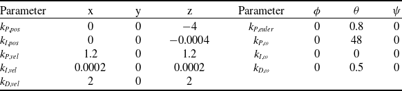
This section lists the parameters needed to test the equations in transition flight simulation for the conceptual lifting-wing UAV designed for this study. First, the relevant geometric parameters are listed in Table A1. In Table A2, the vehicle centre of gravity parameters for the total mass of 3.621 kg. Table A3 lists the relevant propeller parameters, such as positions respective to UAV C.G., tilt angle and rotation direction (1 clockwise and –1 counterclockwise). The inertia matrix is shown in Equation (A1). The time constants used in the simulations are listed in Table A4, of which the brushless motors were obtained from Ref. (Reference Quan20) for a similar propulsion system. The cascaded PID controller gains used in every simulation are listed in Table A6.
 \begin{align}{\tilde I_B} = \left[ {\begin{array}{c@{\quad}c@{\quad}c}{0.1222} {}& 0 {} {}&{0.0211}\\[3pt]0 {} {}&{0.1580} {}& {}0\\[3pt]{0.0211} {}& {}0 {}& {}{0.2491}\end{array}} \right]\end{align}
Appendix B. UAV Aerodynamic data
This appendix shows the aerodynamic data used in the simulations. The aerodynamic coefficients and dynamic derivatives were obtained using the methods of Refs [Reference Hoak25–Reference Houghton and Carpenter27]. Both wing and canard are made of the NACA 4415 aerofoil. Figure B1 depicts the longitudinal aerodynamic coefficients, such as lift, drag and pitch moment coefficients (
 ${C_L}$
,
 ${C_D}$
,
 ${C_m}$
), for the wing, canard and body part of the UAV as a function of local angle-of-attack.
UAV geometric parameters

UAV centre of gravity (C.G.) parameters

Propellers position with respective to C.G., tilt angle and rotation direction

Controls time constants used in the simulations and limits of propellers

Control input limits and conversion constants values

Controller gains used in the simulations
Additionally, in Fig. B2, the relevant aerodynamic longitudinal coefficients at transition trajectory, for the equilibrium condition for the specific configuration of wing mounting angle of 18° and canard mounting angle of 30°, and wing mounting angle of 14° and canard mounting angle of 18°. Figure B3 contains relevant aerodynamic longitudinal derivatives at transition trajectory.
Wing aerodynamic coefficients.

Aerodynamic longitudinal coefficients at transition trajectory for the mounting angle combinations of: (
 ${\delta _w} = {18^ \circ }$
,
 ${\delta _c} = {30^ \circ }$
) and (
 ${\delta _w} = {14^ \circ }$
,
 ${\delta _c} = {18^ \circ }$
).

Aerodynamic longitudinal derivatives at transition trajectory for the mounting angle combinations of: (
 ${\delta _w} = {18^ \circ }$
,
 ${\delta _c} = {30^ \circ }$
) and (
 ${\delta _w} = {14^ \circ }$
,
 ${\delta _c} = {18^ \circ }$
).



