
1. Introduction
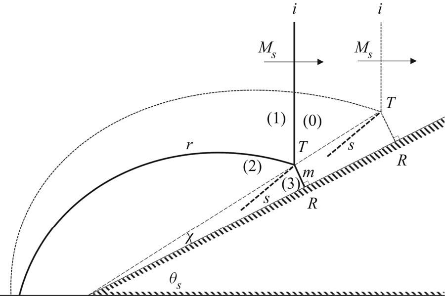
When an incident planar shock wave having a shock Mach number, Ms, impinges upon a surface with a constant inclination angle, θs (i.e. wedge), either a regular reflection (RR) or an irregular reflection (IR) occurs. One type of IR is a Mach reflection (MR), depicted in figure 1. It consists of three shock waves: an incident shock wave, i, a reflected shock wave, r, and a Mach stem, m; and a slip line, s, which separates thermodynamic regions (2) and (3). The three shock waves and the slipstream intersect at the triple point, T. The foot of the Mach stem is perpendicular to the reflecting surface, intersecting with it at the reflection point, R. At this reflection, classified under pseudo-steady flows, the triple point, T, departs from the leading edge of the reflecting wedge and propagates along a straight line with an inclination angle, χ, relative to the surface. The propagation path of T is denoted as the triple-point trajectory, making χ the trajectory angle. The linearity of the trajectory implies that the flow maintains steady characteristics at the vicinity of the triple point and is therefore considered to be self-similar (Ben-Dor Reference Ben-Dor2007).
Wave configurations of a Mach reflection over a straight wedge at two different times.

The presence of a finite-length shock wave (i.e. the Mach stem) indicates that the reflection is governed by the geometry of the boundary conditions. This is the main idea behind Hornung, Oertel & Sanderman's (Reference Hornung, Oertel and Sanderman1979) length-scale concept. When the reflection ceases to communicate with the leading edge of the wedge, a transition to RR takes place. This occurs when the flow behind the reflection point R becomes supersonic. Thus, based on the length-scale concept, the  $\textrm{IR}\rightleftharpoons \textrm{RR}$ transition criterion in pseudo-steady flows is the sonic criterion (Ben-Dor Reference Ben-Dor2007). In this case, the corner-generated signals cannot catch up with the reflection point, making it impossible to obtain a physical length scale that is required for the existence of a finite-length Mach stem (Hornung et al. Reference Hornung, Oertel and Sanderman1979).
Unsteady reflection has been an interest of several studies due to its implications concerning applications such as shock focusing, supersonic aircraft design and detonation. As opposed to pseudo-steady flow, the reflection configuration propagates over a surface with a continuously changing inclination angles (i.e. a continuous change in the boundary condition); as a result, the flow is unsteady, and the aforementioned self-similarity cannot be obtained (Ben-Dor Reference Ben-Dor2007).
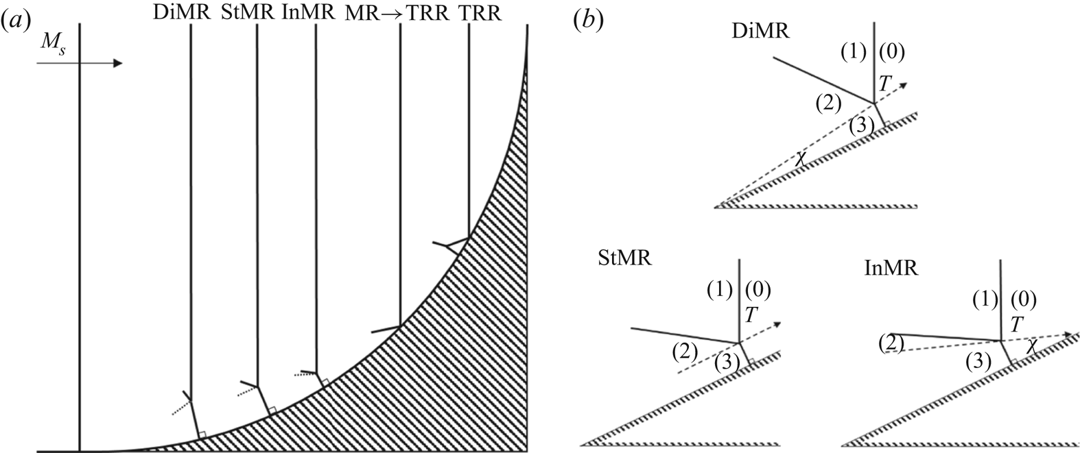
In the unsteady case, the MR evolution over a concave surface with an initial inclination angle of  $\theta _s^i = 0$ is demonstrated in figure 2(a). An incident shock wave travelling with Ms is deformed by the changing surface and an MR is formed. Then dynamic changes in the boundary conditions impose multiple MR types that differ by the triple-point trajectory as shown in figure 2(b). When T moves away from the surface, the reflection is denoted as a direct MR (DiMR). When the trajectory is parallel to the surface (χ = 0), it is considered as a stationary MR (StMR). When T moves towards the surface, the configuration is an inverse MR (InMR). At the intersection point of T with the surface, a transition from MR to transitioned RR (TRR) occurs. The complexity of the MR evolution makes the prediction of the transition point more difficult than the pseudo-steady
 $\textrm{MR}\rightleftharpoons \textrm{RR}$ transition for which there are established transition criteria (Ben-Dor Reference Ben-Dor2007).
Reflection evolution over a concave surface. (a) Types or reflection in chronological order. (b) Types of possible MR configuration in unsteady flow. Direct MR (DiMR), stationary MR (StMR), inverse MR (InMR) and transitioned RR (TRR).

Experimental and numerical results indicated that the  $\textrm{MR}\rightleftharpoons \textrm{RR}$ transition angles in unsteady flows differ from the ones in pseudo-steady flows – extensive data are demonstrated in Ben-Dor's (Reference Ben-Dor2007) book. Experiments performed by Takayama & Sasaki (Reference Takayama and Sasaki1983) over cylindrical surfaces with different radii showed that the MR → TRR transition depends on the Mach strength and the radii of curvature. The transition occurs at larger surface angle than the pseudo-steady criterion; as the radius of curvature decreases, the deviation is increased. However, they noticed that when the radius of curvature was considerably increased, the transition occurred very close to the pseudo-steady criterion. The delay in the transition to TRR was experimentally proven over a single size cylindrical concave surface in the studies of Skews & Kleine (Reference Skews and Kleine2009) and Geva, Ram & Sadot (Reference Geva, Ram and Sadot2013). A recent numerical study by Krassovskaya & Berezkina (Reference Krassovskaya and Berezkina2017) examined concave reflectors of different type and presented this delay as well. These provided a qualitative insight concerning the complex interaction of the flow with the changing surface; however, no quantitative and comprehensive information was given.
Ben-Dor, Takayama & Kawauchi (Reference Ben-Dor, Takayama and Kawauchi1980) suggested, on the basis of experimental observations, that the  $\textrm{MR}\rightleftharpoons \textrm{RR}$ truly non-stationary transition does not follow the known detachment or von Neumann criteria; neither the mechanical equilibrium nor length-scale concepts applied for steady and pseudo-steady flows. Therefore, in the following years they developed several analytical models attempting to predict the transition angles for flows over concave surfaces. Some of these models depended solely on the incident shock Mach number (Ben-Dor & Takayama Reference Ben-Dor and Takayama1985, Reference Ben-Dor and Takayama1986/7; Takayama & Ben-Dor Reference Takayama and Ben-Dor1989), whereas others relied also on the curvature of the surface (Ben-Dor, Takayama & Dewey Reference Ben-Dor, Takayama and Dewey1987b). The one found to best fit the experiments was derived from the corner-generated signals concept mentioned above. Over the concave surface, signals propagate from the leading edge of the surface to point T along the slipstream in a path that can be approximated by the arc length Rcθs, where Rc is the radius of curvature of the surface and θs is the local surface inclination (Ben-Dor & Takayama Reference Ben-Dor and Takayama1985). Their approach was based on the notion that the MR is possible only when the corner disturbances can catch up with the reflection point. However, they mentioned that the model lacks a few details regarding the induced flow condition and has no dependence on the radius of curvature. In later studies, they addressed those issues but stated that further information is required in order to agree with the experiments (Takayama & Ben-Dor Reference Takayama and Ben-Dor1989). The models listed above account for only the influence of the initial disturbance. As will be described in this paper, the remaining part of the surface has a considerable influence on the reflection that must be treated.
Owing to the complex flow fields produced by the reflection process and the occurrence of several types of irregular reflection, the behaviour of the reflection configuration prior to the transition over a concave surface has been the interest in recent studies. Gruber & Skews (Reference Gruber and Skews2013) carried out an experimental study of weak shock waves reflecting from concave surfaces. They showed that a reflected wave does not appear at the initial stages of the reflection. This was attributed to the analytical findings made by Vasilev, Elperin & Ben-Dor (Reference Vasilev, Elperin and Ben-Dor2008) describing weaker forms of irregular reflection (e.g. von Neumann reflection (vNR), Guderley reflection (GR) and Vasilev reflection (VR)) at low values of wedge angles θs. Those types were also noted by Krassovskaya & Berezkina (Reference Krassovskaya and Berezkina2017) in their numerical research of a strong shock wave (Ms = 2.5) reflecting over complex concave surfaces. They suggested that the entire evolution of the various shock configurations is a result of complex subprocesses that depend merely on the type of surface; these processes were assumed to be independent of the type of gas and Ms. It should be noted, however, that their computations were performed for a single type of gas at a single Mach strength. Soni et al. (Reference Soni, Hadjadj, Chaudhuri and Ben-Dor2017) expanded the research over one cylindrical reflector to a double concave cylindrical reflector with several combinations of radii, Rc, and initial surface angles,  $\theta _s^i$. Their main concern were the types of reflection emerging on the second reflector and the locus of transition between them.
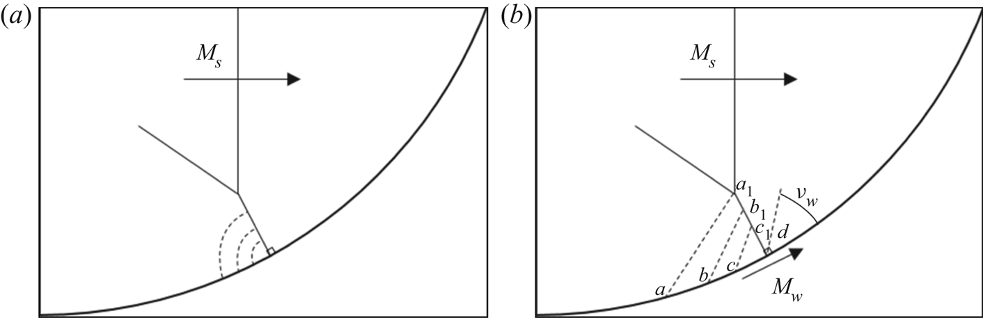
From the gas-dynamics point of view, the induced flow behind a moving shock will be disturbed by the concave wall. At the location where the wall changes its direction, disturbance waves will be generated. These waves in two-dimensional flow are basically cylindrical compression sound waves propagating with the local speed of sound relative to the local flow velocity. The shock will change its shape and be strengthened at the location where the disturbance meets the shock (Han & Yin Reference Han and Yin1993). This analysis is shown in figure 3(a). Experimental investigations of these disturbances were carried by Skews & Kleine (Reference Skews and Kleine2007, Reference Skews and Kleine2009). By introducing small impurities on a concave surface, they were able to capture the perturbation sourcing from these imperfections. In Skews & Kleine (Reference Skews and Kleine2009), the method was used to explain the formation of MR on a concave reflector at the early stages of the reflection. They showed how the incident shock is bent by these disturbances and its strength increases, until a moment where these disturbances coincide, and a distinct kink appeared on the incident shock wave. This is the moment where the Mach stem and the reflected shock waves are formed. The later stages of the reflection and the transition to TRR are described in Skews & Kleine (Reference Skews and Kleine2007). Their study revealed that the reflection configuration is affected by the entire shape of the surface and not only by its initial shape. This notion suggests that previous analytical models that account only for the initial disturbances are inapplicable (Ben-Dor & Takayama Reference Ben-Dor and Takayama1985). They stated that if the curvature of the wall decreases along its length rather than staying constant, the MR will exist farther. This was numerically proven by Krassovskaya & Berezkina (Reference Krassovskaya and Berezkina2017). They examined the reflection configurations over four concave surfaces; all surfaces coincided up to a specific location, resulting in a similar MR. Ahead of this point, the surface curvature differed, which resulted in different transition angles. In their study they pointed out the importance of the ratio between the Mach stem length and the radius of curvature. Since a concave wall consists of an infinite number of changes along the surface, several studies examined simplified geometries that consist of a finite number of variations.
Shock-induced disturbances resulting from an incident shock wave propagating and reflecting over a concave surface. (a) Cylindrical sound waves. (b) Characteristics lines; νw is the angle of the characteristic corresponding to the Mach number of the shock near the surface Mw, where the upward velocity of the disturbance along the Mach stem is varied,  ${W_d}({M_{w,d}}) \gt {W_d}({M_{w,c}}) \gt {W_d}({M_{w,b}}) \gt {W_d}({M_{w,a}})$.

In order to better understand the local influence of surface variation, Ben-Dor, Dewey & Takayama (Reference Ben-Dor, Dewey and Takayama1987a) studied the shock reflection over a double wedge with a single increase of the wedge angle. Krassovskaya & Berezkina (Reference Krassovskaya and Berezkina2017) extended the analysis and numerically computed the reflection over a polyhedron inscribed in a concave cylinder. Their qualitative analysis clearly showed that the entire reflection and transition are affected by the entire surface. They showed that an additional Mach stem configuration is formed on the original MR. This was also shown experimentally by Ram, Geva & Sadot (Reference Ram, Geva and Sadot2015). A similar qualitative analysis of RR over segments of wedges forming a convex surface was performed by Wang & Zhai (Reference Wang and Zhai2020). They provided a qualitative description of the disturbances and found that the reverse RR → MR transition can be predicted by the pseudo-steady transition criterion regardless of shock strength and surface geometry. Yet, the later finding is irrelevant for the concave reflector; since changing the surface geometry and shock strength were found to influence considerably the transition angles. Although being a simplification of the geometry, analysing the cylindrical disturbances is complicated and therefore invalidates the quantitative description of the reflection evolution.
Another approach for tracking surface disturbances relies on the shock-dynamics viewpoint (figure 3b). This concept describes how nonlinear disturbance waves propagate on the shock. As a result, the strength, orientation and shape of the shock wave are varied by local changes. The equations describing the velocities and angles of the disturbances are found in Han & Yin (Reference Han and Yin1993) and are based on the derivation of Whitham (Reference Whitham1957, Reference Whitham1973) and Skews (Reference Skews1967). The displacement in the wall direction can be treated analogously to a piston moving in a shock tube (Han & Yin Reference Han and Yin1993). When the wall is concave, the foot of the incident shock wave is pushed along the surface (so that it accelerates), compression waves are generated and move along the shock. This phenomenon is denoted as shock compression. The information is transmitted along a characteristic straight line (ray) at an angle νw relative to the local surface angle θs. The characteristic is plotted using the following relation:
 \begin{equation}y - {y_w} = (x - {x_w})\tan ({\theta _s} + {\nu _w}),\end{equation}
where xw and yw are the spatial coordinates along the reflecting wedge. The angle νw is estimated by Whitham's (Reference Whitham1957) formulation:
 \begin{equation}\tan ({\nu _w}) = \frac{1}{{{M_w}}}{\left[ {\frac{{(M_w^2 - 1)K({M_w})}}{2}} \right]^{1/2}}.\end{equation}
Here Mw is the Mach number of the foot of the shock along the reflecting surface and K(Mw) is estimated by
 \begin{equation}K({M_w}) = \frac{2}{{(2\mu + 1 + M_w^{ - 2})\left( {1 + \dfrac{2}{{\gamma + 1}}\dfrac{{1 - {\mu^2}}}{\mu }} \right)}}.\end{equation}
Its value changes between K(M) = 0.394 and K(M) = 0.5 for M → ∞ and M = 1, respectively. The parameter μ depends on the local Mach strength and the specific heat capacities ratio:
 \begin{equation}\mu = {\left[ {\frac{{(\gamma - 1)M_w^2 + 2}}{{2\gamma M_w^2 - (\gamma - 1)}}} \right]^{1/2}}.\end{equation}
The velocity at which the disturbance travels upwards along the shock wave, Wd, is estimated as  ${a_0}{M_w}\tan ({\nu _w})$. Since Mw is increased along the concave surface, the resultant angle νw and Wd are increased, resulting in the variation of strength and orientation along the Mach stem. Itoh, Okazaki & Itaya (Reference Itoh, Okazaki and Itaya1981) applied the shock-dynamics relations on a concave surface. It was found that disturbances that occurred behind the Mach stem deformed the Mach stem and therefore must be accounted for. Their transition criterion, for air with shock Mach strengths of 1.5–2, predicted slightly larger angles than the published experiments and larger than the analytical model of Ben-Dor & Takayama (Reference Ben-Dor and Takayama1985).
The present study aims to extend the analysis of MR over a single cylindrical concave surface ( $\theta _s^i = 0$) and its subsequent transition to TRR. In the current study, not only the radii are varied, but also three Mach numbers and three different ideal gases are analysed. High temporal and spatial resolution validated inviscid numerical computations were conducted for the investigation of the detailed evolution analysis. We have limited our analysis to the InMR stage in which the reflected wave and triple point are clearly visible. The interaction of wall disturbances with the reflection is assessed by means of shock-dynamics formulations (Han & Yin Reference Han and Yin1993). By analysing the polyhedron inscribed in a concave cylinder, it is shown that the use of the shock-dynamics concept is suitable for the InMR stage. A qualitative and quantitative description of the reflection process and transition is given for the cylindrical concave surface.
2. Numerical method and validation
The study is mainly based on numerical computations. Experiments were conducted for the sole purpose of validation. The following subsections present concise descriptions of the numerical computations, experimental procedure, validation and post-processing. For further information about the computations and extended validation, the interested reader is referred to Geva et al. (Reference Geva, Ram and Sadot2013), Ram et al. (Reference Ram, Geva and Sadot2015) and Geva, Ram & Sadot (Reference Geva, Ram and Sadot2018).
2.1. Numerical computations
A control-volume-based technique was implemented by a commercial solver ANSYS® FLUENT (Academic release 19.1). Second-order space and time schemes were used to approximate the inviscid Euler equations. The spatial discretization of the convection and diffusion terms was evaluated using a second-order upwinding total-variation-diminishing method that employed the Barth–Jespersen minmod limiter (Barth & Jespersen Reference Barth and Jespersen1989). Gradients in the upstream cell were calculated by the Green–Gauss node-based gradient evaluation (Holmes & Connel Reference Holmes and Connel1989; Rausch, Batina & Yang Reference Rausch, Batina and Yang1992). Transient terms in the differential equations were calculated by second-order explicit time-stepping integration based on a four-stage Runge–Kutta method (Jameson, Schmidt & Turkel Reference Jameson, Schmidt and Turkel1981). The numerical scheme has been successfully applied to the complementary reflection over a convex cylindrical surface in a former study (Geva et al. Reference Geva, Ram and Sadot2018). Owing to the use of a commercial program, rigorous validation and verification were done against the highest temporal and spatial resolution experiments available nowadays (Ram et al. Reference Ram, Geva and Sadot2015). The numerical results were found to be in excellent agreement with the experiments; therefore the scheme may be assumed to be reliable. A structured grid was refined at several levels. Thus, the results presented in this paper are grid-independent.
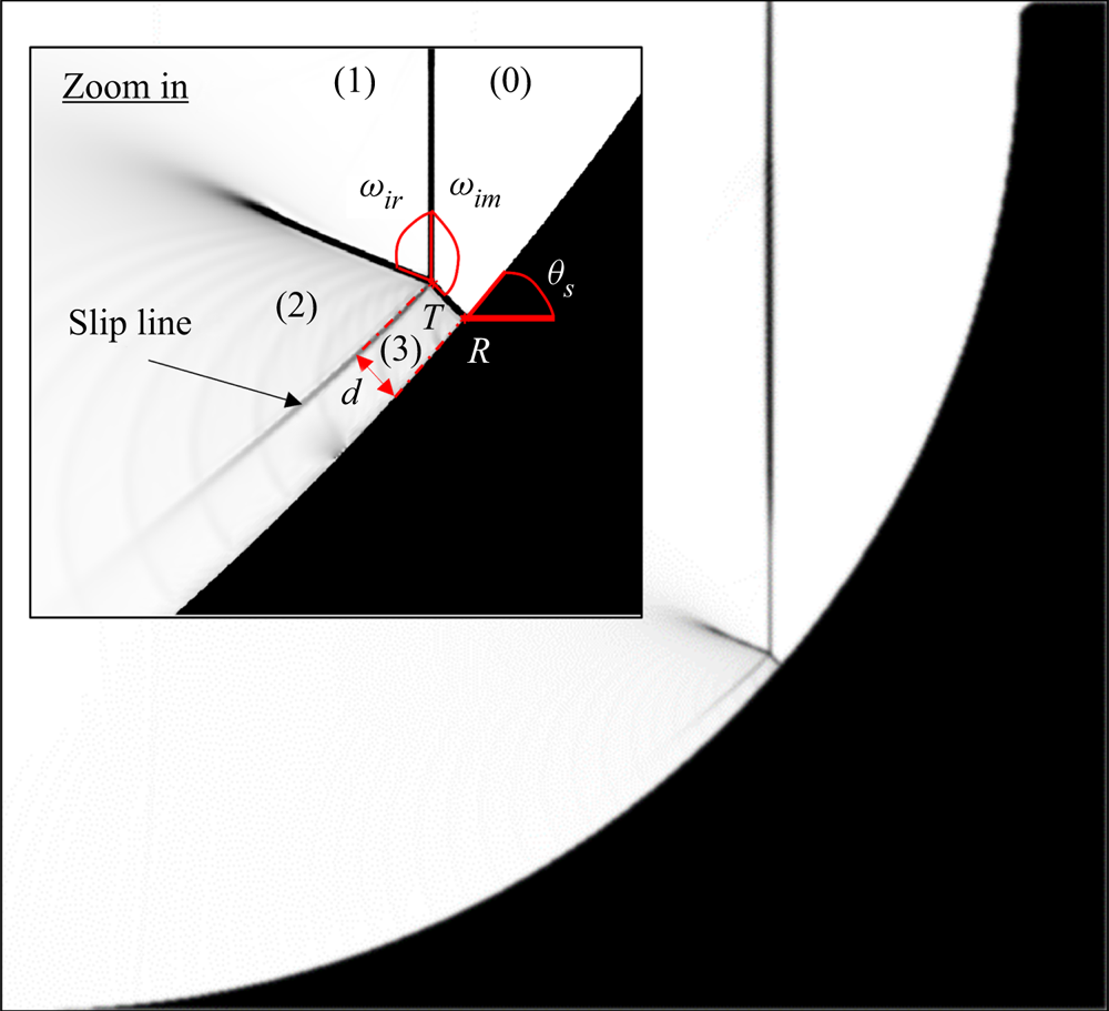
Data extracted from the simulation included the two-dimensional fields of the flow conditions (density, pressure and temperature) in each flow time step (set to be about Δt = 1 μs); grid spatial resolution corresponds with the experiments such that  $\Delta x = \Delta y = 0.03\;\textrm{mm}$ (§ 2.2). Using the gradient of the density field,
 ${\boldsymbol{\nabla}}\rho (x,y)$, a numerical schlieren image was generated, as can be seen in figure 4. Using the schlieren image enabled the extraction of geometrical properties, namely the angle between the reflected and incident shock waves, ωir, the angle between the incident shock wave and the Mach stem, ωim, the local surface inclination, θs, the reflection point, R, the triple point, T, and the distance between them, d. The error in the measurement of the angles due to visualization limitations was found to be ±2°. The error of the value of the coordinates was set by the grid resolution to be ±2 pixels or ±0.06 mm. The value of θs was analytically calculated using the curvature, Rc, and the horizontal coordinate of the reflection point, Rx, that is given by
 \begin{equation}{R_x} = {R_c}\sin ({\theta _s}).\end{equation}
This calculation, combined with the spatial resolution, yielded an error of the inclination angle of ±0.1° in magnitude. Computations were made for reflections over three cylindrical concave surfaces having radii of 40, 60.6 and 100 mm. The examined Mach numbers were 1.3, 1.4 and 1.5. Three different gases were tested, air, argon and CO2, specified in table 1. Both air and argon were treated as perfect gases, while CO2 was considered as a thermally perfect gas due to its noticeable sensitivity to the temperature variations expected during the reflection. The reflection over polyhedra inscribed in concave cylinders having radii of 40 and 60 mm were computed in air for Mach strength 1.3. In the following subsection, a successful comparison between computations and experiments of a 40 mm concave cylindrical surface at Mach strength of 1.3 is given.
Corresponding schlieren image from a simulation over a 100 mm cylindrical surface at Mach number 1.3, depicting the geometrical configuration and features of the shock reflection.

Specifications of gases.

2.2. Experimental and numerical validation
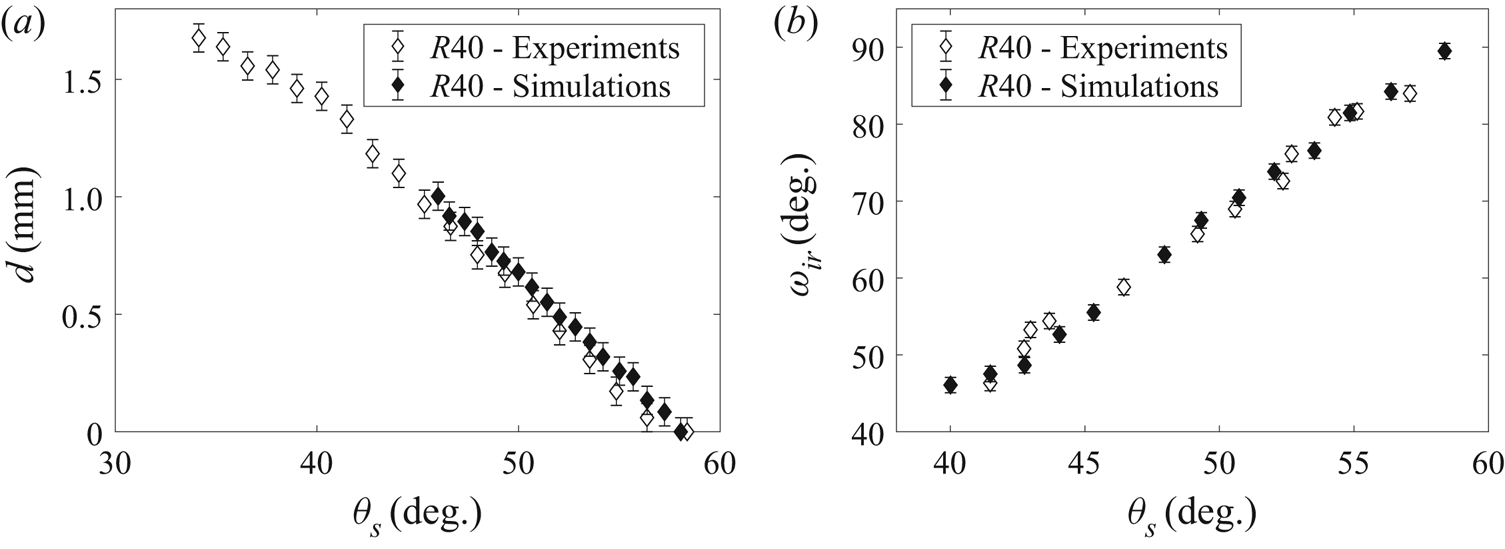
Experiments were conducted using a vertical shock tube with a driven section 4.5 m long and a cross-section of 80 mm × 80 mm. The test chamber (same cross-section) is connected to the driven section, having two transparent PMMA (polymethylmethacrylate) windows for flow visualization based on the schlieren method. The driver and driven sections are separated by a fast-opening valve. A D7000 Nikon camera captured a single frame (16.2 MP) of the reflection configuration. An in-house automated control system, together with the optical system, allowed a 0.03 mm spatial resolution and a 1 μs temporal resolution between each two frames. The test model (Al-7071 machined to N2 surface finish) selected is a coupled concave–convex surface. For the purpose of validation, a 40 mm cylindrical concave part with an initial inclination angle of 0° was chosen. Experiments with incident shock Mach number of 1.3 were analysed in the same manner as numerical computations up to the point of transition mentioned in the previous subsection. Two geometrical parameters, d and ωir, were compared as seen in figure 5. Further validation using the same experimental apparatus and numerical schemes appears in Geva et al. (Reference Geva, Ram and Sadot2018). Since the simulations are considered to be in good agreement with the experiments and analytical predictions presented, the following analyses relied exclusively on the computational results.
Validation of the simulations according to the geometrical parameters of the reflection for Ms = 1.3, R = 40 mm: (a) comparison of d versus θs; and (b) comparison of ωir versus θs.

3. Results and discussion
The computations were performed for three different radii, three Mach strengths and three different gases. The first two were found in a former publication to influence the transition considerably (Ben-Dor Reference Ben-Dor2007), whereas the last, to the best of the authors’ knowledge, was not previously examined in the unsteady case. Both the geometrical configuration and the thermodynamic properties of the dynamic reflection process were investigated numerically up to the MR → TRR transition point. At the beginning of the reflection process, the DiMR is of weak nature – the Mach stem is curved, and the reflected wave is not visible. This means that the triple-point location could not be accurately extracted. Therefore, the following analysis presented in this study is limited to the InMR type of reflection in which the MR configuration is clearly seen. The first subsection is devoted to the analysis of reflections over different radii at different Mach strengths. The discussion is extended with the analysis of the reflection process in different types of gases, i.e. different γ and a 0 (§ 3.2). Section 3.3 presents the use of shock-dynamics relations to evaluate the thermodynamic conditions behind the Mach stem. Section 3.4 shows the simulations of reflection over polyhedra in order to explain the entire reflection process and the shock-dynamics limitations.
3.1. MR configuration over the concave surface
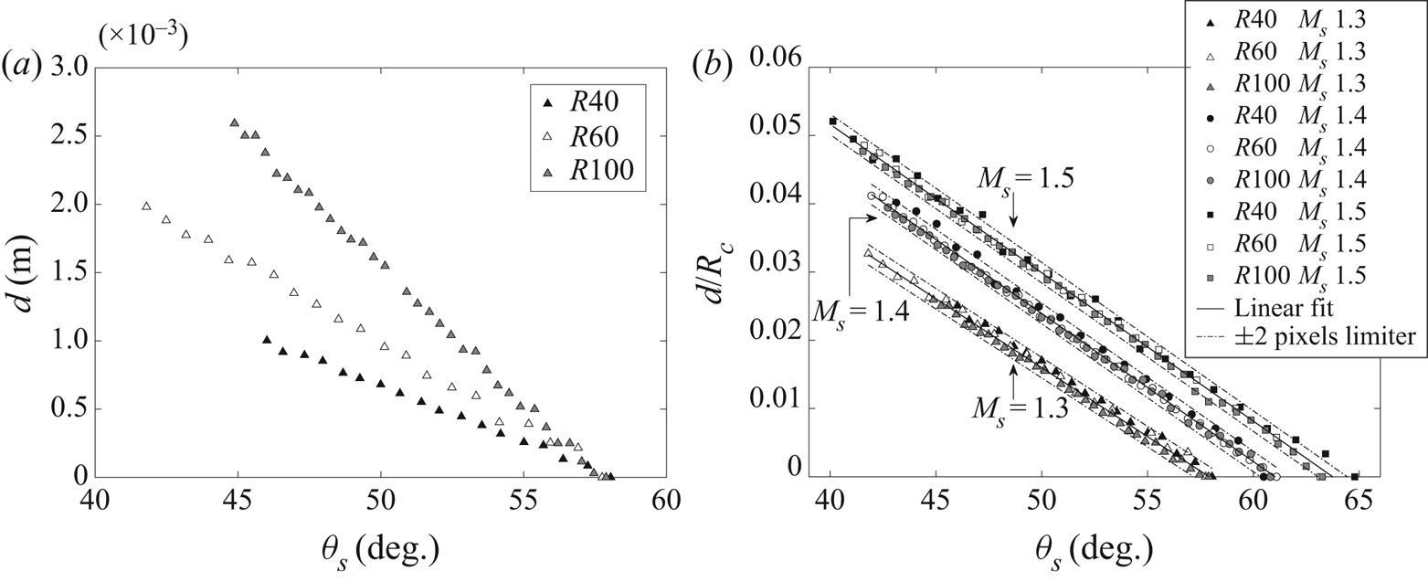
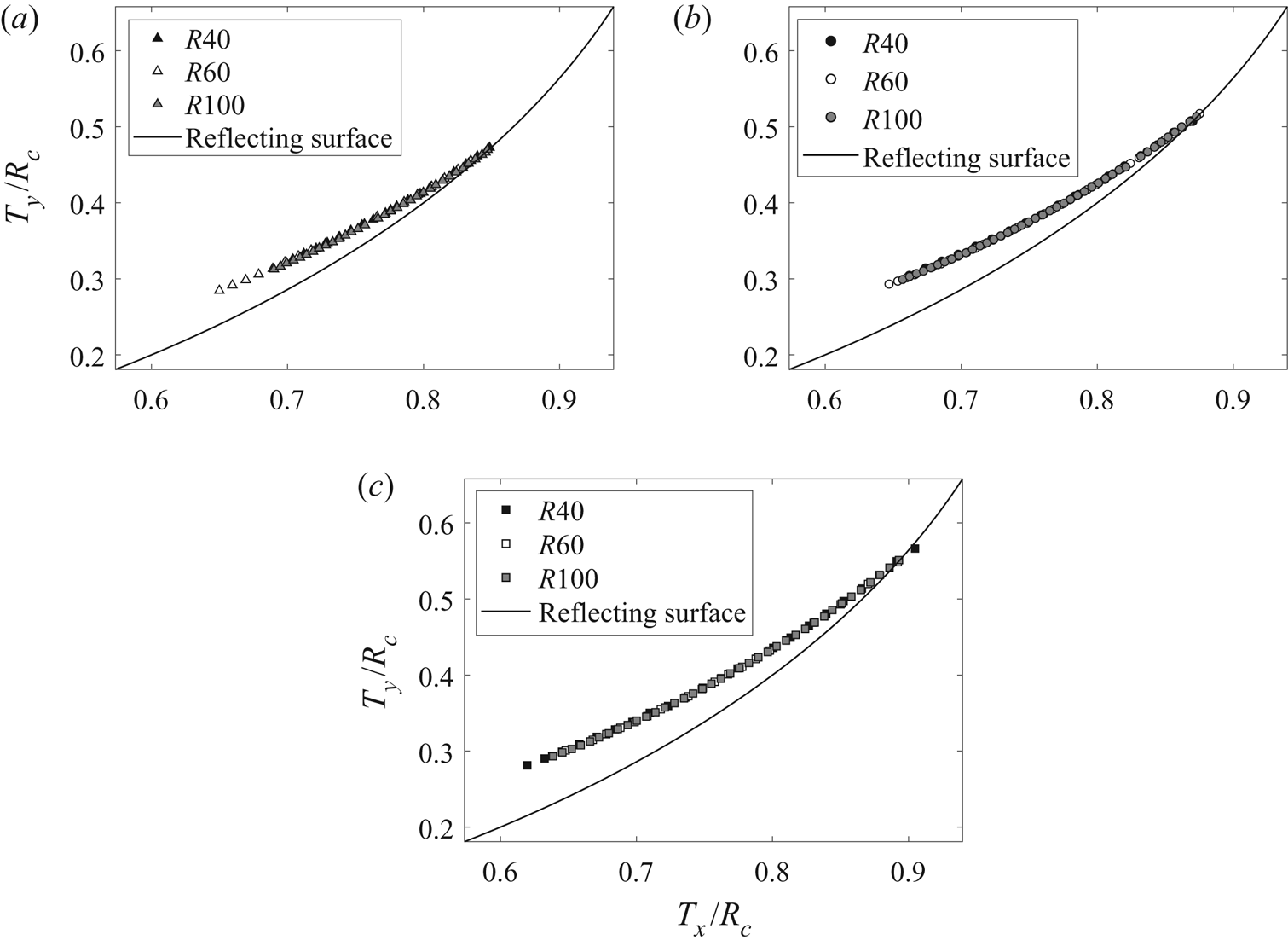
Shock-wave reflections over cylindrical concave surfaces with different curvatures (Rc = 40, 60.6 and 100 mm) and incident shock Mach numbers of Ms = 1.3, 1.4 and 1.5 were studied numerically. Figure 6 shows the Mach stem length versus the surface angle for the conditions listed above. Figure 6(a) shows the Mach stem lengths at Ms = 1.3 using three different surfaces. The Mach stem is larger for larger radii of curvature. However, the transition angle is insensitive to the radius of curvature, as can be seen by the intersections of the curves with the horizontal axis. Figure 6(b) extends the results and includes two additional Mach strengths. By normalizing the Mach stem lengths with the corresponding radius, Rc, the results for each Mach strength coincide and the resultant curves are nearly parallel. The values are bounded within a ±2 pixel limiter as described in § 2.1. The use of Rc as a proper normalization length is consistent with Krassovskaya & Berezkina (Reference Krassovskaya and Berezkina2017), suggesting the importance of the ratio d/Rc in the reflection process over different shapes of concave surfaces. The fact that, for each Mach number, the curves coincide eliminates the influence of surface radii on the transition, as opposed to the belief that smaller radii cause a delay in the transition (Ben-Dor Reference Ben-Dor2007). Since the Mach stem condensation process and eventually the transition to TRR are independent of radius of curvature, it implies that the Mach stem trajectory is similar for a given Mach number. This is shown in figure 7, which describes the spatial location of the triple point in a dimensionless domain, i.e. x/Rc and y/Rc planar coordinates.
Mach stem length as a function of surface angle for three radii of curvature: (a) Ms = 1.3; and (b) normalized value for different Mach strengths and radii of curvature.

Triple-point trajectory in a non-dimensional planar space for: (a) Ms = 1.3; (b) Ms = 1.4; and (c) Ms = 1.5.

As Ms increases, so does the ratio d/Rc, which causes a delay in transition corresponding to a larger transition angle  $\theta _s^t$, as reported by Takayama & Sasaki (Reference Takayama and Sasaki1983) and Ben-Dor & Takayama (Reference Ben-Dor and Takayama1985). This can be attributed to an increase in the disturbance strength as the incident Mach number increases (Han & Yin Reference Han and Yin1993). Stronger disturbance travels faster along the shock; it affects greater parts of the incident shock wave, which are deformed due to the shock-compression phenomenon. Therefore, the accumulation of compression waves, which forms the reflection wave, occurs at a higher location on the incident shock wave – making the triple point first appear at a larger distance from the surface.
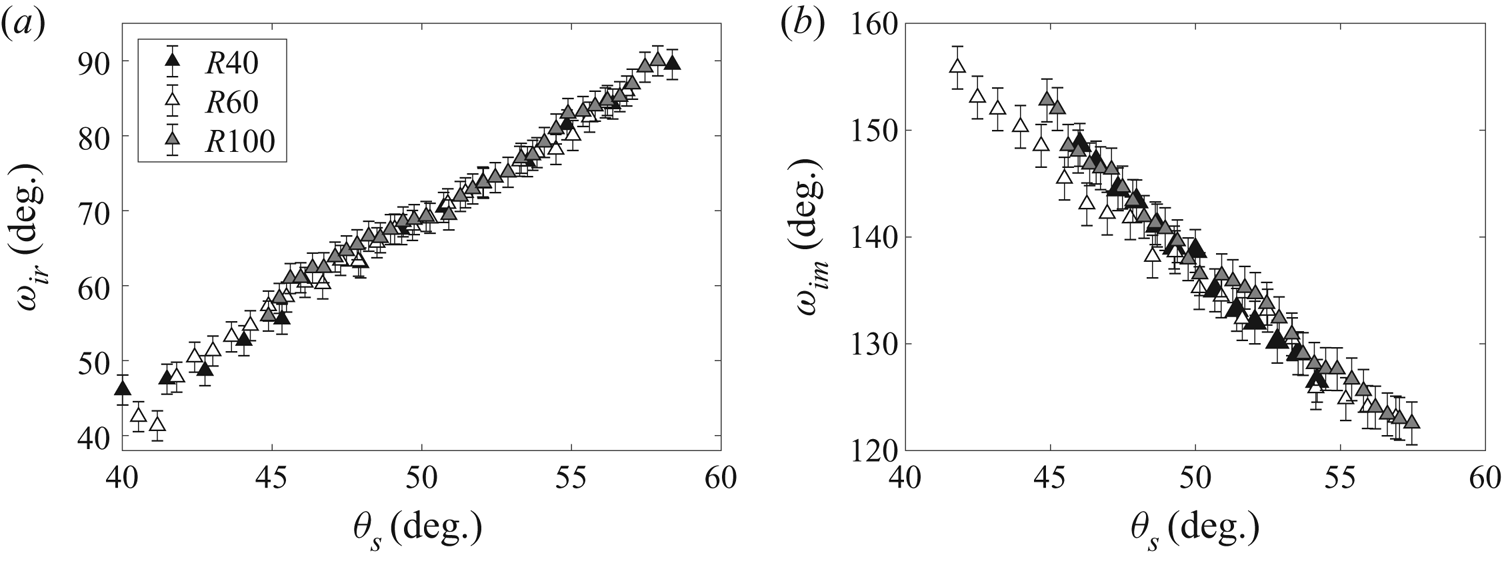
Figure 8 shows that not only the Mach stem is similar, but also the entire MR configuration. This is demonstrated by comparing the angles between the shock waves for a given surface angle (ωir between the incident and the reflected shock waves, ωim between the incident shock and the Mach stem). It should be noted that, at smaller surface angles, the Mach stem is extremely curved, which makes the assessment of ωim less accurate; this explains the increased deviation in figure 8(b) for smaller surface angles.
Comparison of the angular configuration for Ms = 1.3: (a) ωir; and (b) ωim.

The fact that the Mach stem is curved indicates that each segment along the Mach stem travels with a different strength (Skews & Kleine Reference Skews and Kleine2007). The foot of the Mach stem travels with the highest speed due to the immediate interaction with compression waves originating from the changing surface. The instant response of the foot of the Mach stem to the surface is due to the perpendicularity requirement in the reflection point. Higher segments along the Mach stem will be informed by the current change in the surface at later times. For larger Mach stem length, the curvature is more pronounced, and the assumption made by all analytical models of a straight and constant-strength Mach stem is inadequate. Yet, as the Mach stem decreases, the curvature decreases, denoting that its strength may be approximated as constant.
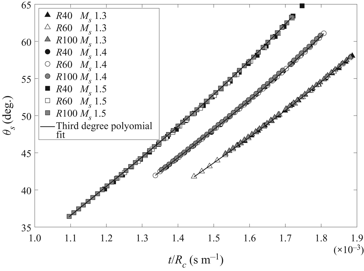
The response of the foot of the Mach stem can be normalized as well; this is demonstrated in figure 9, which shows the change in surface angle with respect to a normalized time. From this figure, the velocity of the reflection point along the surface can be derived. This point travels with tangential velocity  ${R_c}{\dot{\theta }_s}$, which corresponds to a Mach strength of
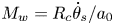 ${M_w} = {R_c}{\dot{\theta }_s}/{a_0}$ (a 0 is the speed of sound ahead of the Mach stem). From figure 9, one can obtain that, for a given Mach number, the change of surface angle with normalized time is similar, and therefore the reflection communicates with the surface equally. From shock-dynamics consideration, information from the surface travels along the Mach stem with a velocity that depends slowly on the local Mw. The reflected shock wave is forced to adjust itself to the flow conditions near the triple point, resulting in a similarity of the entire MR configuration and imposing the same thermodynamic conditions between the waves.
Surface inclination angles versus flow time normalized by surface radius.

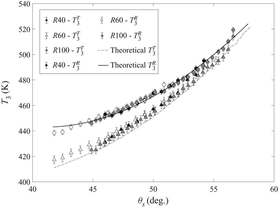
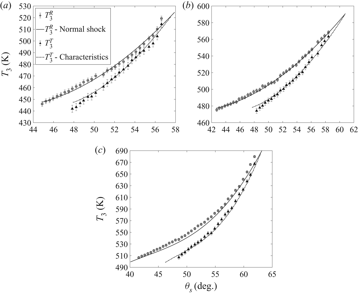
The equality in the thermodynamic conditions is demonstrated by comparing the temperatures over the three surfaces at a specific incident Mach number. Figure 10 shows the temperatures computed behind the reflection point  $(T_3^R)$ and the triple point
 $(T_3^T)$. The maximum errors in the temperature values were defined to be ±2 K near the reflection point and ±3 K near the triple point due to the averaging technique implemented in the post-processing procedure. The dashed line, the estimated
 $T_3^T$, was estimated by the oblique shock relation adjacent to the triple point, using the following equation:
 \begin{equation}\frac{{T_3^T}}{{{T_0}}} = \frac{{\left[ {1 + \dfrac{{(\gamma - 1)}}{2}M_0^2{{\sin }^2}{\phi_3}} \right]\;\left[ {\dfrac{{2\gamma }}{{\gamma - 1}}M_0^2{{\sin }^2}{\phi_3} - 1} \right]}}{{\dfrac{{M_0^2{{\sin }^2}{\phi _3}}}{2}\;\dfrac{{{{(\gamma + 1)}^2}}}{{(\gamma - 1)}}}},\end{equation}
where  ${\phi _3} = 180^\circ{+} {\phi _1} - {\omega _{im}}$ is the wave angle of the Mach stem, and
 ${M_0} = {M_s}/\sin ({\phi _1})$, where
 ${\phi _1} = 90^\circ{-} {\theta _s} - \chi$ is the incident wave angle (Ben-Dor Reference Ben-Dor2007). The trajectory angle χ was extracted from figure 7(a). The solid line corresponds to the temperature at the reflection point where the shock is perpendicular to the surface. This line was computed by the normal shock-wave relations with the local foot of the Mach number of the Mach stem at each surface angle, Mw:
 \begin{equation}\frac{{T_3^R}}{{{T_0}}} = \frac{{[2\gamma M_w^2 - (\gamma - 1)]\,[(\gamma - 1)M_w^2 + 2]}}{{{{(\gamma + 1)}^2}M_w^2}}.\end{equation}
Values of the temperatures behind the Mach stem near T and R in region (3) versus surface inclination for Ms = 1.3 with comparison to theoretical estimations.

The flow behind the foot of the Mach stems follows, in excellent agreement, the normal shock-wave relation with the Mach number Mw, whereas the temperatures estimated behind the triple point are slightly above the dashed line. This could be attributed to the evaluation of ϕ 3, which depends on visualization limitation. Yet the comparison supports the variation of strength along the Mach stem; the stronger the Mach stem, the larger is the temperature behind it. The foot of the Mach stem travels with the largest Mach strength, and therefore the temperatures near the reflection point are larger than those behind the triple point. As the Mach stem decreases in length, its strength becomes somewhat similar and the temperatures behind it approach each other. At the transition to TRR (marked by the dashed vertical line), the temperature behind the reflection point and the triple point must be equal.
So far, we have demonstrated that the Mach stem behaviour is similar as long as the incident Mach number is the same. It was suggested that this similarity is a result of similar interactions between the reflection configuration and the surface when the time is normalized by the radius of curvature of the surface. In § 3.3, shock dynamic relations will be utilized to prove this idea.
3.2. Effects of specific heat capacities ratio on the reflection process
The previous section demonstrated how the incident Mach number strength influences the MR and the transition to TRR. Since the similarity with respect to the surface radius Rc has been established, the analysis in this section will be performed only for a concave cylinder having a radius of 100 mm. The reflection is analysed for three incident Mach strengths of 1.3, 1.4 and 1.5 in an environment of three gases, air, argon and CO2 (described in § 2).
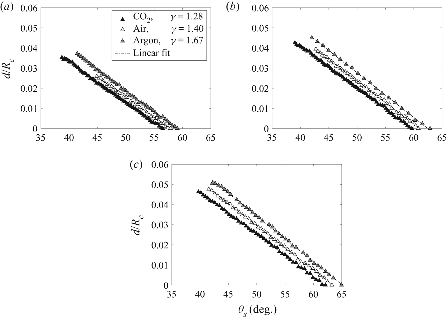
Figure 11 shows the non-dimensional length of the Mach stem against the surface angle for the three different gases. One can immediately observe that the slopes are parallel, with a distinct offset. For the same surface angle, the length of the Mach stem is larger for larger γ. This increase in the value of γ is translated to a delay in the MR → TRR transition. In order to explain this behaviour, the surface disturbances should be accounted for.
Non-dimensional Mach stem length d/Rc against a local surface inclination for different types of gases: (a) Ms = 1.3; (b) Ms = 1.4; and (c) Ms = 1.5.

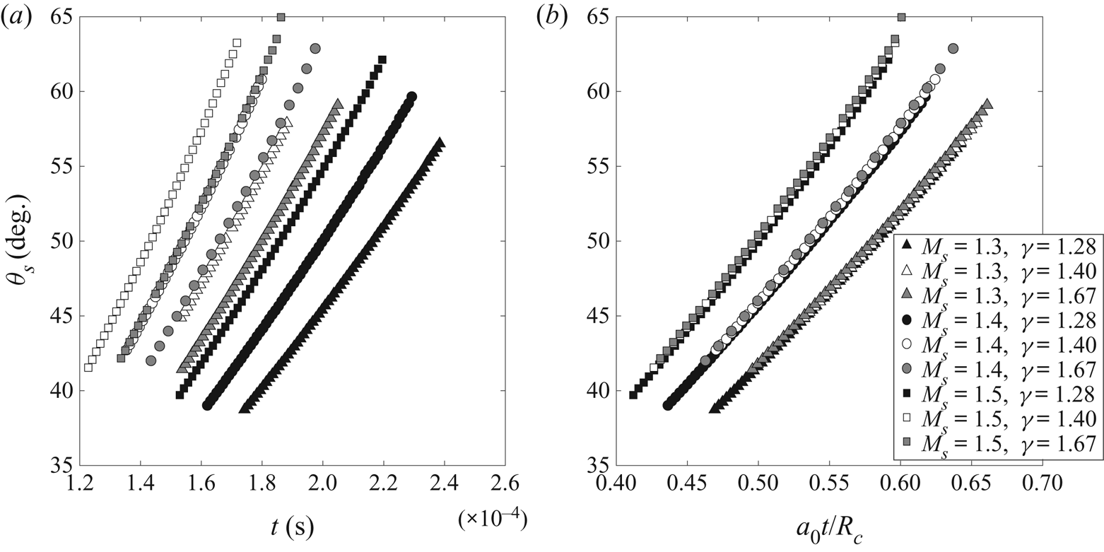
The strength of surface disturbances depends on the local Mach number at the foot of the Mach stem, Mw. This, as was demonstrated earlier, depends on the variation rate of the surface angle. The surface angle at the foot of the Mach stem is plotted with respect to the flow time in figure 12(a); no particular trend is observed. However, when the surface angle is plotted against a normalized length  ${a_0}t/{R_c}$, the lines for each incident Mach number strength coincide (figure 12b). This implies that, for a specific incident Mach number, the variation of the Mach number at the foot of the Mach stem (at the reflection point) is the same. Since the lines coincide, it implies that
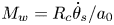 ${M_w} = {R_c}{\dot{\theta }_s}/{a_0}$ is the same for all three gases. Nevertheless, since different gases are involved, having different γ and different speeds of sound, the influence of these parameters must be clarified.
Time-based evolution of surface angle for various Ms and gases (Rc = 100 mm) as a function of: (a) flow time; and (b) non-dimensional flow time.

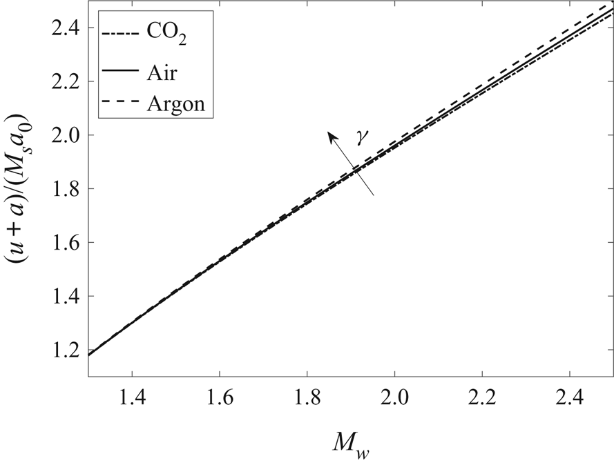
For the gases tested, increasing γ will result in a higher velocity of the surface disturbance, and the ratio between the velocity of the disturbance and the velocity of the incident shock wave, i.e. 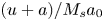 $(u + a)/{M_s}{a_0}$, is larger as well (see appendix A, figure 22). Since the compression sound waves move faster when an incident shock wave reflects over the concave surface, these disturbances will eventually coincide at a larger distance along the shock. Thus, the formation of the triple point is at a larger distance from the surface. These conclusions are also supported qualitatively by the analytical model suggested by Ben-Dor & Takayama (Reference Ben-Dor and Takayama1985).
Because the curves 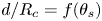 $d/{R_c} = f({\theta _s})$ are parallel, the delay in the transition seems to depend only on the initial normalized length of the Mach stem. Thus, changing the gas has no influence on the evolution of InMR and its termination. An analogous observation was made by Kleine et al. (Reference Kleine, Timofeev, Hakkaki-Fard and Skews2014) with respect to Reynolds number (Re) over convex surfaces. By holding the incident Mach number constant, they changed Re by lowering the pressure; a clear offset of the RR → MR transition was demonstrated. Afterwards in the process, it was shown that the rate at which
 $d/{R_c}$ increases with respect to θs in the DiMR configuration is similar.
From geometrical considerations, the incident shock wave, which travels with a constant velocity  ${M_s}{a_0}$, pulls the upper part of the Mach stem at the triple point. The horizontal distance that the upper part of the Mach stem travels is equal to
 ${T_x} = {M_s}{a_0}t$, whereas the foot of the Mach stem travels a horizontal distance of
 ${R_x} = {R_c}\sin ({\theta _s})$. Since both triple point and reflection point are on the same Mach stem, they are related so that
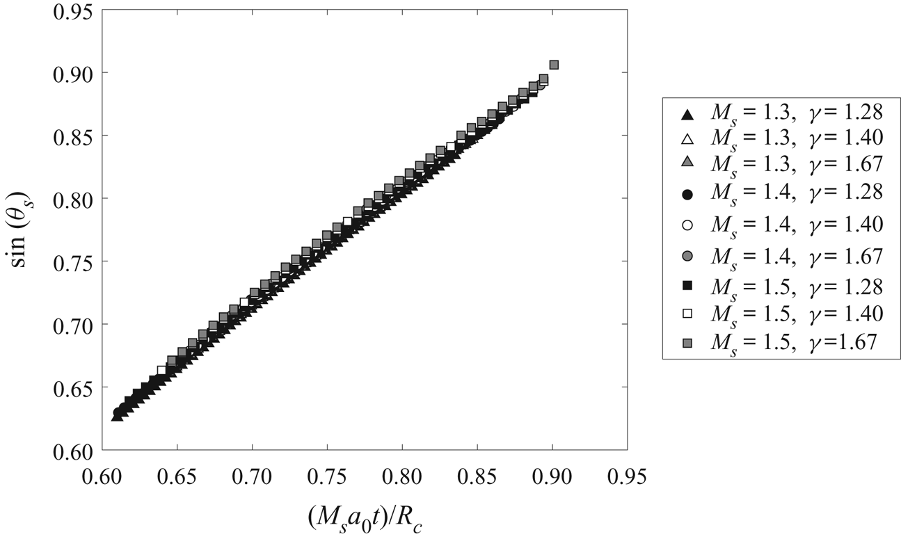
 \begin{equation}{R_x} \propto {T_x} \to \sin ({\theta _s}) \propto \frac{{{M_s}{a_0}t}}{{{R_c}}}.\end{equation}
In the case of RR, where the incident shock is connected to the reflection point, we expect that  ${R_c}\sin ({\theta _s}) = {M_s}{a_0}t$. For the MR case, the value of sin(θs) as a function of the normalized distance
 ${M_s}{a_0}t/{R_c}$ is plotted in figure 13. It is shown that all nine cases examined result in a single universal trend. This normalization results in a single curve that describes the variation of the surface angle over concave surfaces. It accounts for different incident Mach strengths, different gases and various radii, and provides information concerning the rate at which the foot of the Mach stem varies along the surface. The knowledge of the variation in time of the surface angle can be used to obtain the Mach strength of the foot of the Mach stem, Mw, which in turn provides a meaningful insight regarding how the disturbances propagate along the Mach stem. This will be explained using the shock-dynamics relations.
Sine of surface angle versus non-dimensional velocity multiplied by Ms.

3.3. Analysis based on shock-dynamics concepts
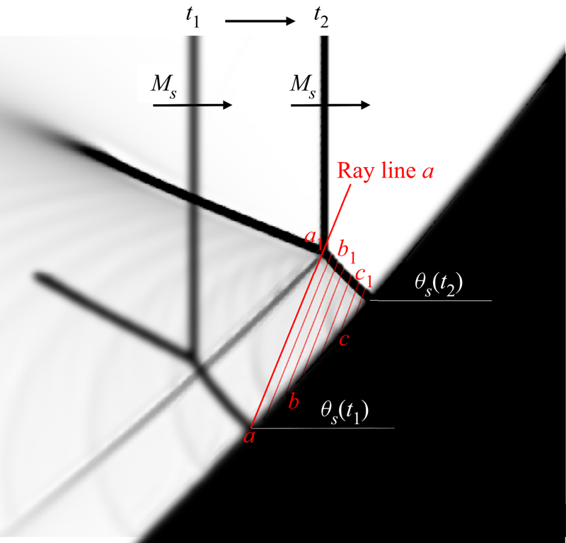
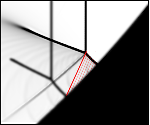
The shock-dynamic relations are used to elucidate how surface disturbances propagate along the shock in the unsteady MR. When the Mach stem encounters a change in the surface angle, a disturbance will propagate upwards along the shock. The characteristic carrying the information from the surface point at which it was generated can be plotted at each point using (1.1). Figure 14 shows two successive time frames of the InMR process. At time t 1, the shock disturbances travels upwards along the Mach stem with  ${W_d}({M_{w,a}})$; the resultant characteristic that originates from point a is plotted (line a–a 1). As the Mach stem advances, newly formed characteristics are observed (points b and c). These lines intersect with the Mach stem at time t 2 at different locations (a 1, b 1 and c 1). Along the straight line, the strength and orientation of the Mach stem are conserved, which means that the conditions of the Mach stem segments at points a 1, b 1 and c 1 correspond to the conditions at the origins a, b and c, respectively. If one knows the variation of Mw along the surface, these lines can be estimated. By tracking the origin of the characteristics, the strength and orientation of the segments of the Mach stem can be evaluated at each moment. Since the orientation and strength of each segment are known, the thermodynamic condition behind the Mach stem can be derived as well. At the origins (points a, b, c, etc.) normal shock-wave relations can be used due to the perpendicularity of the foot of the Mach stem.
Numerical schlieren image of two successive time frames showing the geometrical reflection configuration (Rc = 100 mm, Ms = 1.3) and the characteristic lines formed by the propagation of the Mach stem along the surface.

To prove that this concept is valid in InMR, we compare the temperatures estimated by the characteristic methods with the computed temperatures from the simulations,  $T_3^R$ and
 $T_3^T$ (figure 15). The simulation results are marked by symbols. The temperature at the reflection point,
 $T_3^R$, at each time is estimated using the normal shock-wave relation with the local foot of the Mach stem Mach number, Mw (a similar routine as was explained for the results shown in figure 10). For the estimation of the temperature at the triple point,
 $T_3^T$, we have not used (3.1) as before. Instead, we followed the origins of the characteristic lines. Figure 14 illustrates this procedure. The idea behind this analysis is that, at a specific flow time (t 2), one needs to find the origin of the characteristic line that intersects with the triple point (‘a’ in figure 14). If such an intersection exists, it means that the temperature behind the triple point is
 $T_3^T({t_2}) = T_3^R({t_1})$ or
 $T_3^T({\theta _2}) = T_3^R({\theta _1})$. Predicted values of
 $T_3^T$ are presented in figure 15 (for γ = 1.4, Ms = 1.3, 1.4, 1.5 and Rc = 100 mm). Analytical Mw values at each surface angle were calculated using the third-degree polynomial fits to the variation of the surface angle with time shown in figure 9.
Temperature values in region (3) of the reflection (γ = 1.4, Rc = 100 mm) as a function of surface angle (T – triple point, R – reflection point). Lines represent analytical estimations: (a) Ms = 1.3; (b) Ms = 1.4; and (c) Ms = 1.5.

The dashed curve in figure 15 corresponds to the resultant temperature using the characteristic method. Excellent agreement was found with numerical measurements of  $T_3^T$. A slight deviation is demonstrated at smaller surface angles. This is probably due to the goodness of the polynomial fit at the edges
 ${R_c}{\theta _s} = f(t)$. This analysis can be used to predict the entire temperature distribution behind the Mach stem by tracing the origin of the characteristics between times t 1 and t 2. Assuming no dissipation of energy along the characteristic, and that the disturbance propagates in a medium with no discontinuities (such as a slip line), the analysis is valid.
The effectiveness of this method in the InMR supports the similarity in geometrical and physical properties of the reflection. The geometrical relation between the non-dimensional length of the Mach stem at time t 2 with respect to the characteristic line formed at time t 1 is as follows:
 \begin{equation}\tan ({\nu _w}) = \frac{{\Delta d}}{{{R_c}\Delta {\theta _s}}}\quad \Rightarrow \quad \frac{{\Delta d}}{{{R_c}}} = \tan ({\nu _w})\Delta {\theta _s},\end{equation}
where  ${R_c}\Delta {\theta _s}$ is the distance that the reflection point has travelled during time
 $\Delta t = {t_2} - {t_1}$ (approximated as a straight line if
 $\Delta {\theta _s}$ is small). It was demonstrated that for the different cases
 ${M_w} = f(\dot{\theta })$ is the same, and therefore
 ${\nu _w} = f({M_w})$, (1.2). The Mach stem is informed by the surface variation in the same manner as long as the shape of the concave surface is the same.
Regarding the finding of Takayama & Sasaki (Reference Takayama and Sasaki1983) concerning  ${R_c} \to \infty$, it was shown that the MR → TRR transition approaches the pseudo-steady-state transition angles. This can be explained as follows. If
 ${R_c} \to \infty$, the rate at which the angles of the surface changes approach zero, resulting in a finite and constant Mach number at the foot of the Mach stem
 $({M_w} = {R_c}{\dot{\theta }_s}/{a_0})$. Constant Mw implies that each increment of change in the surface angle
 $(\Delta \theta )$ will result in a disturbance travelling along the Mach stem at the same rate, Wd. As a result, the foot of the Mach stem strength will remain constant (the same as the self-similar behaviour of a single wedge). Since the radii examined in this study are limited, further study is required to examine this hypothesis.
The following subsection describes the limitation of shock-dynamics relations at early stages of MR over concave surfaces. It is shown that, if a discontinuity is present, the strength and direction along a characteristic cannot be conserved. To simplify the explanation, we use polyhedra (i.e. series of constant inclination wedges) inscribed in two cylindrical concave cylinders.
3.4. Reflection over a multi-faceted concave surface
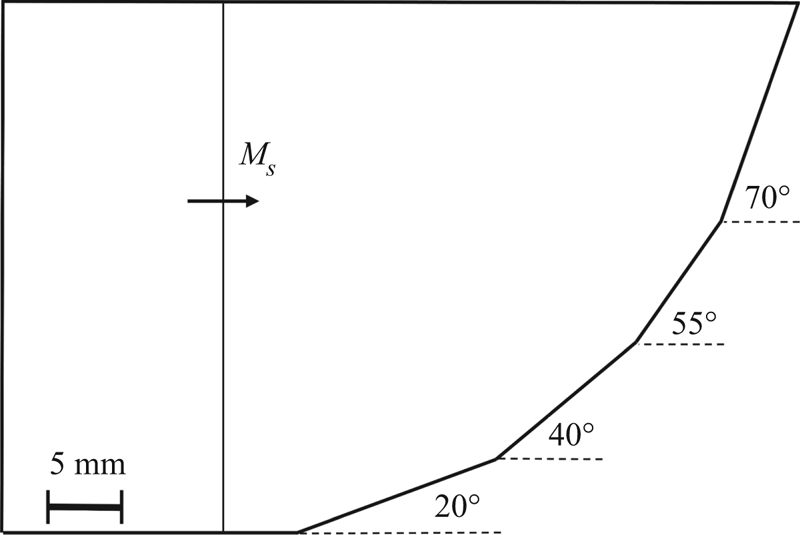
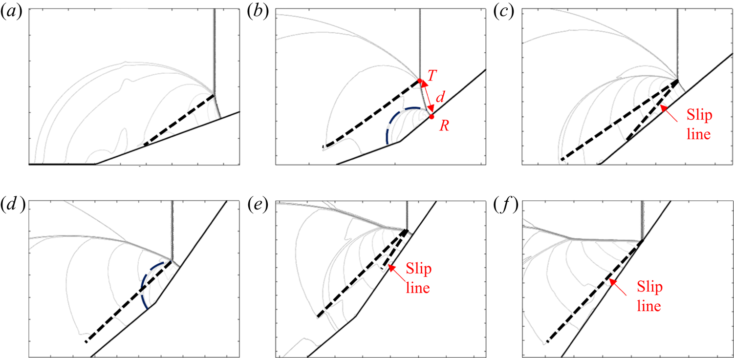
This section includes the investigation of the reflection in air over two polyhedra inscribed in a concave cylinder having radii of 40 and 60 mm. The polyhedra consist of four segments having wedge angles that were arbitrarily chosen to be 0°, 20°, 40°, 55° and 70° (figure 16). The resultant density contours were recorded in each time step and are shown in figure 17. The use of similar geometry and qualitative analysis by means of density maps were previously performed by Krassovskaya & Berezkina (Reference Krassovskaya and Berezkina2017). We extend their analysis by comparing two different radii of curvature and using the shock-dynamics equations to describe the process.
Schematic illustration of the spatial domain selected for the simulation of a shock-wave reflection over a multi-faceted concave surface of Rc = 40 mm.

Density contour lines at six different time instants for the reflection over a multi-faceted concave wedge (γ = 1.4, Ms = 1.3, Rc = 40 mm): (a) first wedge; (b) disturbance generated over the second wedge corner creating a second triple point; (c) second disturbance meets the first triple point over the second wedge; (d) disturbance generated over third wedge point; (e) InMR configuration over third wedge; and (f) transition to TRR over third wedge. Dashed lines are the slip lines.

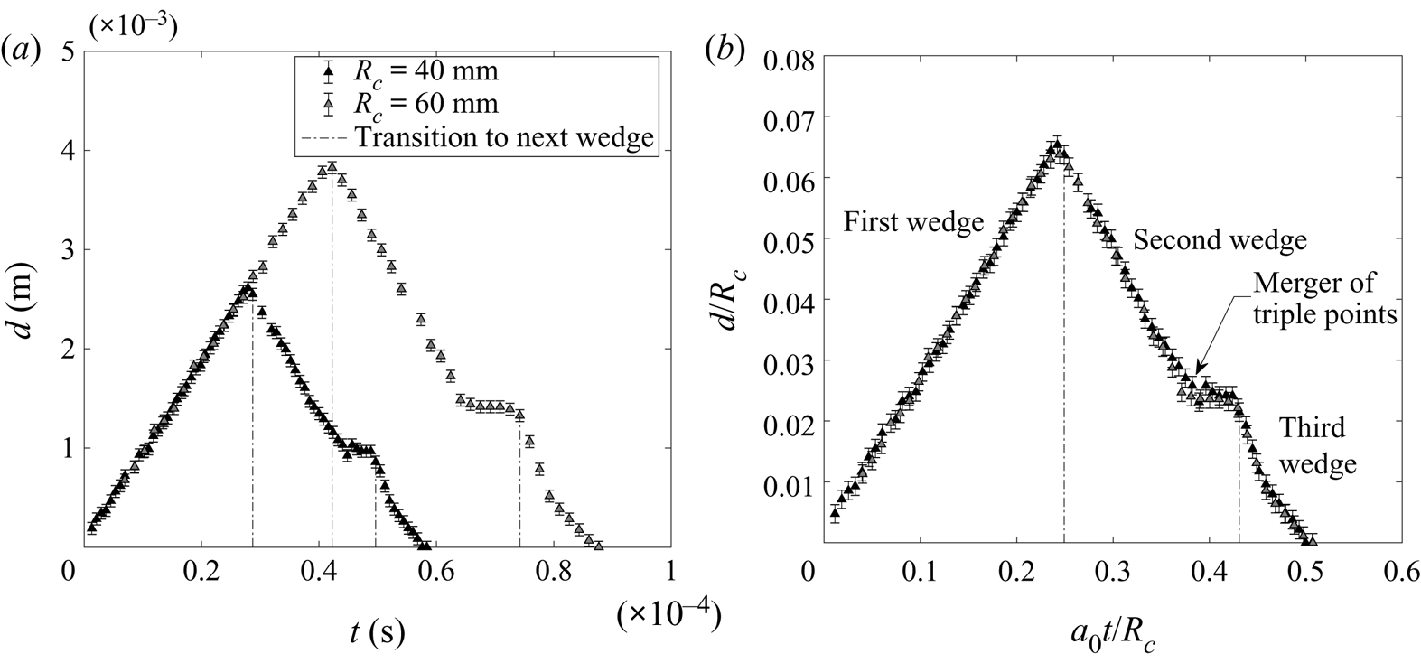
Based on the density contours, the locations of the reflection point, R, and triple point, T, were extracted. These locations were then used to measure the Mach stem height, d (symbols are marked in figure 17b). The time-dependent evolution of the Mach stem height is presented in figure 18(a), where the vertical dashed lines indicate the moments where the reflection point reaches the next wedge. As expected, a similarity in the normalized Mach stem length is observed in figure 18(b). The evolution of the reflection will be explained using figures 19 and 20, which can be interpreted in terms of disturbances due to changes that the induced flow experiences (i.e. gas-dynamics point of view) and shock-dynamics concept (disturbances that the shock experiences). The propagation process can be broken down into the following stages.
Mach stem height as a function of time for the reflection process over a multi-faceted concave surface: (a) Mach stem length; and (b) non-dimensional Mach stem length.

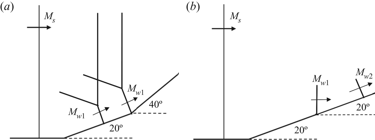
Reflection over the second wedge can be transformed into an equivalent surface: (a) original conditions; and (b) the Mach stem can be considered vertical if the surface is shifted.

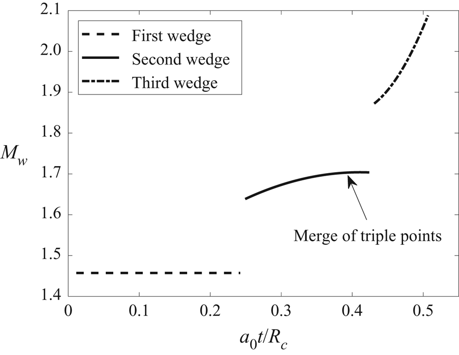
Mach number of the reflection point as a function of non-dimensional time for the reflection process over a multi-faceted concave surface.

3.4.1. Stage 1 – Reflection over first wedge
At the first wedge, the reflection is simply a pseudo-steady MR. A Mach stem is immediately established and grows linearly in a self-similar manner (figure 17a). From the gas-dynamics concept, a single disturbance is generated at the corner of the wedge; both triple point and reflection point are aware of the surface inclination and they travel at constant speeds in their respective directions. Figure 18(b) shows how the Mach stem grows over the first wedge; this stage is a DiMR of weak nature (small surface angle), and thus it is denoted as a vNR (Vasilev et al. Reference Vasilev, Elperin and Ben-Dor2008; Krassovskaya & Berezkina Reference Krassovskaya and Berezkina2017). From shock-dynamics considerations, due to the sudden change in the surface angle, there are no shock-compression waves propagating along the shock. However, there is a discontinuous wave that propagates along the shock; this wave changes the strength and orientation of the incident wave immediately (Han & Yin Reference Han and Yin1993).
3.4.2. Stage 2 – Reflection over second surface
The reflection over the second wedge is seen in figure 17(b). When the induced flow behind the Mach stem passes through the second wedge, a disturbance propagates and bends the original Mach stem until a kink is formed on the original Mach stem. This results in a second triple point that is generated on the original Mach stem. This phenomenon was elaborated in Ben-Dor et al. (Reference Ben-Dor, Dewey and Takayama1987a), Ram et al. (Reference Ram, Geva and Sadot2015) and Krassovskaya & Berezkina (Reference Krassovskaya and Berezkina2017). The presence of the second disturbance enhances the Mach stem strength only beneath the new triple point. Above the new triple point, the Mach stem is not aware of the change in surface inclination. The original triple point travels at the same angle as on the first wedge,  $\theta _{s1}^{} + \chi$. This trajectory angle is smaller than the required inclination
 ${\theta _{s1}} + {\theta _{s2}} = 40^\circ$. Therefore, the original triple point moves towards the surface and the Mach stem length, measured from R to the original triple point, is decreased. This is shown in figure 18(b), the MR varies from DiMR to InMR. The new disturbance propagates upwards, so the new triple point approaches the original one. The two triple points approach each other, until a merging moment is obtained. This is shown in figure 17(c) and is also marked by an arrow in figure 18(b). At that instant the entire Mach stem is aware of the second corner and no subsequent perturbations communicate with it. From the shock-dynamics point of view, the sudden surface change produces a discontinuity along the shock wave which is in contact with the surface; this shock is the Mach stem inclined by 20° from the vertical axis with Mach strength of Mw 1 (figure 19a). Ram et al. (Reference Ram, Geva and Sadot2015) showed that this oblique wave can be considered vertical, with respect to the horizon, if an equivalent surface is used. Thus, it may be reasonable to assume that a Mach stem inclined by 20° that propagates over a 40° wedge is similar to a shifted case in which a vertical wave, travelling with Mw ,1, propagates on another 20° wedge (figure 19b). So, the discontinuity forms another Mach stem on the bottom of the wave. The bottom configuration is denoted as DiMR. There is a mutual influence of the two discontinuities along the Mach stem, which cannot be accounted for merely by the shock-dynamics relations. When they coincide, the Mach stem length is constant until the third wedge is reached. This constant length cannot be explained by pseudo-steady reflection over a single wedge of
 ${\theta _{s1}} + {\theta _{s2}} = 40^\circ$, because, in the latter, the Mach stem length varies.
3.4.3. Stage 3 – Reflection over third wedge and transition to TRR
When the reflection point impinges upon the third wedge, a third disturbance is generated. This disturbance communicates with the entire Mach stem (figure 17d); the entire length of it is aware of the surface change. Figure 18(b) shows that, at the moment at which the reflection point reaches the third wedge, a decrease in the Mach stem length is initiated (figure 17e). The InMR persists up to the transition to a regular reflection shown in figure 17(f). During this stage no discontinuity is observed along the Mach stem and the reflection is truly InMR.
Figure 20 shows the Mach number of the foot of the Mach stem, Mw, along the three wedges. This Mach number was computed as  ${M_w} = \sqrt {{{\dot{x}}^2} + {{\dot{y}}^2}} /{a_0}$, where x and y are the reflection point coordinates and a 0 is the speed of sound ahead of the Mach stem. At the first wedge, the pseudo-steady reflection, the velocity of the reflection point is constant, and the resultant Mach number Mw is constant as well. On the second wedge, the foot of the Mach stem accelerates in an asymptotic manner until the moment where the triple points merge; this moment is marked by an arrow. The mutual influence of the original MR with the bottom MR varies the velocity at the foot of the Mach stem. After the merging, the velocity of the reflection point remains nearly constant until reaching the third surface. At the third wedge, the foot of the Mach stem constantly accelerates due to the disturbance arising from the corner of the third wedge. In view of the ongoing acceleration and persistence of an InMR, it is deemed that this is the only comparable stage to the InMR process of a smooth concave presented in § 3.1.
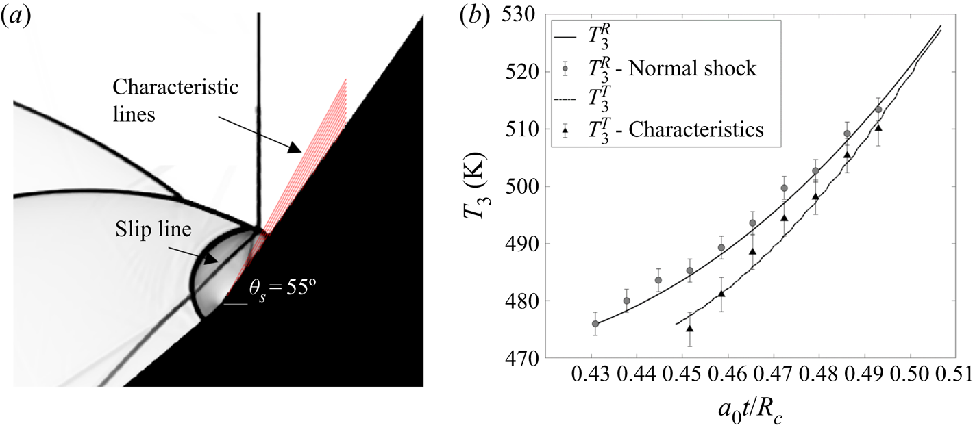
If a distinct discontinuity is present as on the second wedge, the strength and direction along a characteristic cannot be conserved. Consequently, we apply the shock-dynamics relations only on the third surface, similar to the procedure that was done in figure 15. The Mach stem strength at its foot, Mw, on the third surface (figure 20) is used to plot the characteristics as shown in figure 21(a). Since Mw varies along the surface, this means that several surface characteristics exist along the surface. The evaluated temperature values behind the reflection point are based on (3.1) using the Mw at each time. The triple point is obtained by tracking the origins of characteristics similar to the procedure previously executed. A comparison between the estimated temperatures and the temperatures extracted from simulations indicates that this concept is feasible at this stage due to the excellent agreement that is shown (figure 21b). In the early stages, before InMR, the presence of a slip line indicates the variation of thermodynamic conditions. Thus, it cannot be confidently assumed that information along the characteristics remains the same. This notion requires further investigation when applied on the concave surface where changes in the surface inclination are gradual and not sudden.
Using the characteristic method on the third wedge. (a) The characteristics on the third surface plotted on a schlieren image. (b) Temperatures behind the Mach stem with comparison to normal shock relation and characteristics prediction.

4. Conclusions
The unsteady Mach reflection evolution over cylindrical concave surfaces with an initial inclination angle of 0° and three different radii of curvature was examined by means of inviscid validated numerical computations. The analysis focused on moderate shock-wave strength (Ms = 1.3–1.5) and three different types of perfect gas, air, argon and CO2 (γ = 1.4, 1.67 and 1.28, respectively). The geometrical configuration of an InMR was analysed up to the transition to TRR. Disturbance propagation analysis based on gas-dynamics and shock-dynamics considerations were applied to facilitate a better understanding of the reflection process. Based on the shock-dynamics viewpoint, in which the information of the disturbances is conserved along straight lines (family of characteristics), predictions of flow conditions behind the Mach stem in the InMR process were obtained. In addition, shock-dynamics concepts corroborate the similarities that were found in the analysis. It was established that the reflection is similar with respect to a characteristic length scale – the surface's radius. Since the geometrical properties of the reflection scaled by the radius of curvature are similar, so are the flow conditions. However, since the values of the surface curvature in this study are limited, it is as yet unclear whether this type of similarity holds true when  ${R_c} \to \infty$, where the concave surface resembles the reflection over a straight wedge. Two noticeable features were revealed when different gases were analysed. The first is that the normalized height of Mach stem decreases with respect to the surface angle similarly, regardless of the gas. The offset in transition angles is observed due to a difference in the triple-point locations along the incident shock, at which the Mach stem was initially formed. The location of this initial formation is explained in terms of disturbance velocities. Furthermore, the foot of the Mach stem strengths were found to be similar as well. Based on these observations, a universal reciprocal relation for describing the surface angle variation over a cylindrical concave surface was found. This accounts for different radii of curvature, and different gases under variation of incident Mach numbers. The rate by which the surface angle changes dictates how wall disturbances generate and propagate. Additional simulations performed over polyhedra inscribed in circular cylinders were used to explain the reflection process and to support the use of the characteristic technique in InMR. With the addition of ideas from shock-dynamics, the current findings could be established as a basis for future analytical models.
Acknowledgements
This research was supported by the Israel Science Foundation (Grant No. 1045/15). M.G. is supported by Tel-Aviv University and by Ben-Gurion University of the Negev.
Declaration of interests
The authors report no conflict of interest.
Appendix A
The value of the induced velocity behind the foot of the Mach stem was analytically predicted using the equation
 \begin{equation}u = \frac{2}{{\gamma + 1}}\left( {{M_w} - \frac{1}{{{M_w}}}} \right)\,a,\end{equation}
where a is the speed of sound corresponding to flow conditions, meaning temperature  $T_3^R$:
 \begin{equation}a = \sqrt {\gamma \frac{{\bar{R}}}{M}T_3^R} .\end{equation}
The parameter  $\bar{R} = 8314\;{\rm J}\,{\rm kmol}^{-1}\,{\rm K}^{-1}$ is the universal gas constant, and M (kg mol−1) is the molar mass of the specific gas.
Figure 22 depicts the value of u + a divided by Msa 0 as a function of the reflected-point Mach strength Mw. It shows that the ratio 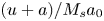 $(u + a)/{M_s}{a_0}$ increases as γ increases.
The ratio between the velocities of the wall-generated disturbance (u + a) and the incident shock wave (Msa 0) as a function of the reflection point's Mach strength.