1. Introduction
Type synthesis of mechanisms is one of the central problems within mechanism and machine theory. It aims to find the optimal mechanism structure required for a desired practical application. Numerous scholars have studied the type synthesis problem over the years, and the most important studies in this field include the works of Grübler [Reference Grübler1], Assur [Reference Assur2], Dobrovolsky and Artobolevsky [Reference Dobrovolsky and Artobolevsky3], Freudenstein [Reference Freudenstein, Dobrjanskyj and Görtler4], Hunt [Reference Hunt5], Tsai [Reference Tsai6], Kong and Gosselin [Reference Kong and Gosselin7], Gogu [Reference Gogu8], Dai [Reference Kuo and Dai9], and Hervé [Reference Li, Hervé and Ye10]. They not only devised some innovative mechanisms using diverse techniques but also introduced and classified different families of such mechanisms.
A significant contribution to mechanism systematization has been made by Artobolevsky. In his famous five-volume work “Mechanisms in Modern Engineering Design” [Reference Artobolevsky11], Artobolevsky described a large number of mechanisms and classified them into the following families: lever mechanisms, slotted-link mechanisms, slider-crank mechanisms, cam and friction mechanisms, gear mechanisms, ratchet mechanisms, flexible- and elastic-link mechanisms, wedge mechanisms, lever-screw mechanisms, electric mechanisms, and hydraulic and pneumatic mechanisms.
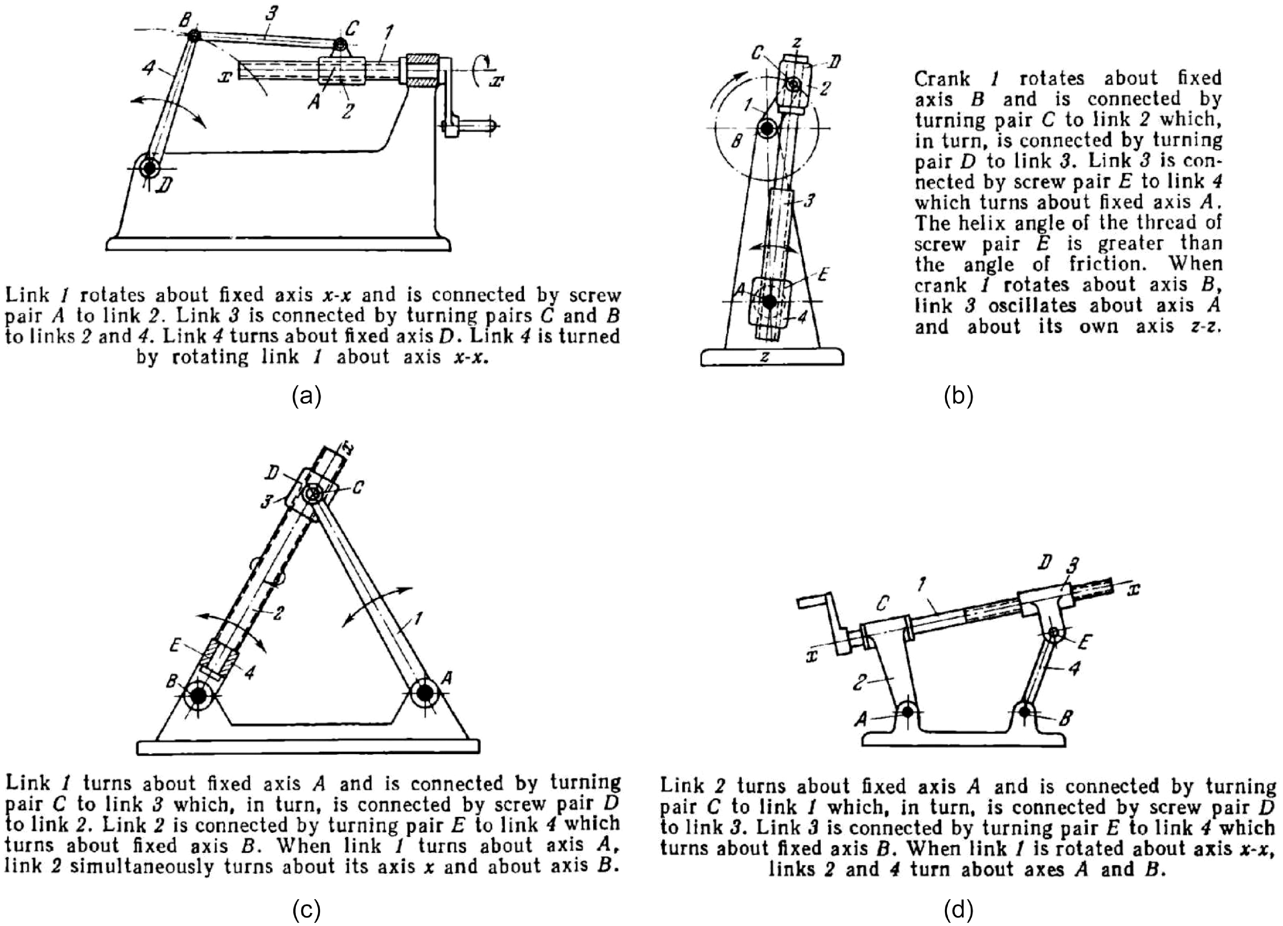
Among these families, lever-screw mechanisms look quite attractive from both a scientific and practical point of view. These mechanisms are based on kinematic chains with lower pairs and include at least one helical joint (Figure 1). Most of the links in these mechanisms move in parallel planes. This allows reducing dynamic loads in the direction normal to these planes. At the same time, some links perform spatial motion, and they are typically considered the output links. To our knowledge, there are no studies devoted to the type synthesis of such lever-screw mechanisms.
Lever-screw mechanisms can have different structures. This paper focuses on five-bar single-loop 4R1H mechanisms. These mechanisms include four revolute (R) joints and one helical (H) joint. Figure 1 illustrates several 4R1H mechanisms presented by Artobolevsky in his work [Reference Artobolevsky11, vol. 2]. Each mechanism comprises a base and four moving links (# 1–4). The planar part of the mechanisms represents a kinematic chain with revolute joints. This structure simplifies the designing and manufacturing of the mechanisms, which makes their development perspective for practical applications.
Some 4R1H lever-screw mechanisms presented by Artobolevsky in his work [Reference Artobolevsky11, vol. 2]: (a) # 2229; (b) # 2231; (c) # 2233; (d) # 2236 (original figures and text).

The mechanisms shown in Figure 1 are single-loop mechanisms with one degree of freedom (1-DOF). Despite their simple structure, mechanisms of this type have become the subject of numerous studies and the foundation of many robotic devices like walking robots [Reference Liang, Ceccarelli and Takeda12, Reference Zhang, Yang, Gui, Chang, Zhao, Yang and Chen13], foldable architectures [Reference Lang, Brown, Ignaut, Magleby and Howell14, Reference Deng, Huang, Li and Liu15], rehabilitation systems [Reference Gonçalves, Rodrigues, Humbert and Carbone16, Reference Zhao, Zhu, Zi and Li17], and grippers [Reference Robson, Ghosh and Soh18, Reference Chen, Lai, Yang, Zhang and Yao19]. In paper [Reference Fomin and Ivanov20], we proposed an original 4R1H mechanism for mixing operations and justified its benefits compared to planar mechanisms.
The 4R1H mechanisms presented in [Reference Artobolevsky11] have been devised by intuition without using any concise approach, and most of the mechanisms still remain unstudied. The current article aims to fill this gap: it gives some insights into the synthesis and analysis methods of 4R1H mechanisms and introduces a few novel mechanisms. We will look at the design process of such mechanisms, starting with their type synthesis and finishing with numerical simulations and physical prototyping. The paper has the following organization. Section 2 presents the type synthesis of a new class of 1-DOF 4R1H mechanisms. The subsequent sections study one mechanism of this class, but the presented techniques can be adapted to any 4R1H mechanism. Section 3 verifies the mechanism has one DOF and analyzes the motion type of its output link. Section 4 examines singular configurations of the mechanism. Section 5 analyzes mechanism kinematics and expresses positions, velocities, and accelerations of all the links in terms of the input motion. Section 6 performs a dynamic analysis and gives a procedure to compute the motor torque required to realize the specified input motion. Section 7 shows the virtual prototype of the considered mechanism and its physical prototype designed from the computer-aided- design (CAD) model. This section also presents numerical examples: using the geometrical and inertial parameters of the developed model, we illustrate the application of the proposed theoretical methods. Sections 8 and 9 discuss the results of the performed research and mention directions for future investigations.
2. Type Synthesis
Type synthesis of 4R1H mechanisms involves combining two kinematic chains with two different motion patterns. This approach is similar to the synthesis method based on group theory [Reference Li, Hervé and Ye10], and we have applied it recently to develop various lever-screw mechanisms [Reference Fomin and Antonov21]. Unlike the latter work where we considered a type synthesis of a general class of lever-screw mechanisms, here we will focus on 4R1H mechanisms in more depth.
The first kinematic chain that we consider corresponds to planar motion. We can describe this chain by (unit) vector
 $\hat{\mathbf{v}}$
orthogonal to the motion plane. The second chain corresponds to cylindrical motion. Vector
 $\hat{\mathbf{u}}$
and point
 $A$
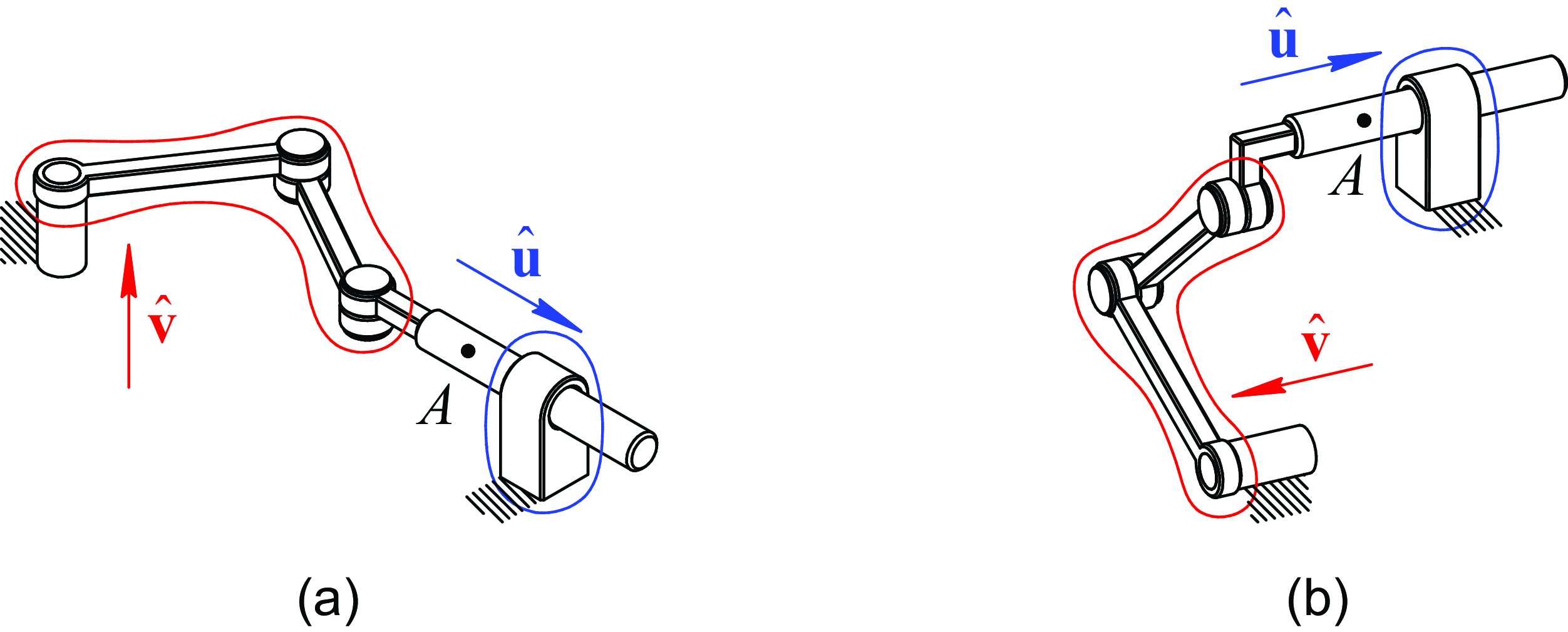
characterize the direction and location of the axis of this cylindrical motion (Figure 2). There are two ways to combine these kinematic chains to get a workable mechanism:
-
1. Vectors
 $\hat{\mathbf{v}}$
and
$\hat{\mathbf{u}}$
are orthogonal. The chains have a common translation along vector
$\hat{\mathbf{u}}$
(Figure 2a).
-
2. Vectors
$\hat{\mathbf{v}}$
and
$\hat{\mathbf{u}}$
are parallel. The chains have a common rotation about the axis passing through point
$A$
parallel to vector
$\hat{\mathbf{u}}$
(Figure 2b).


The considered kinematic chains correspond to the so-called motion subgroups [Reference Li, Hervé and Ye10, ch. 4]. Therefore, if we combine these chains as stated above, the synthesized mechanisms will retain their mobility in all configurations (except for singularities).
Possible ways of combining kinematic chains with planar (red) and cylindrical (blue) motion types: (a) along common translational motion; (b) along common rotational motion.

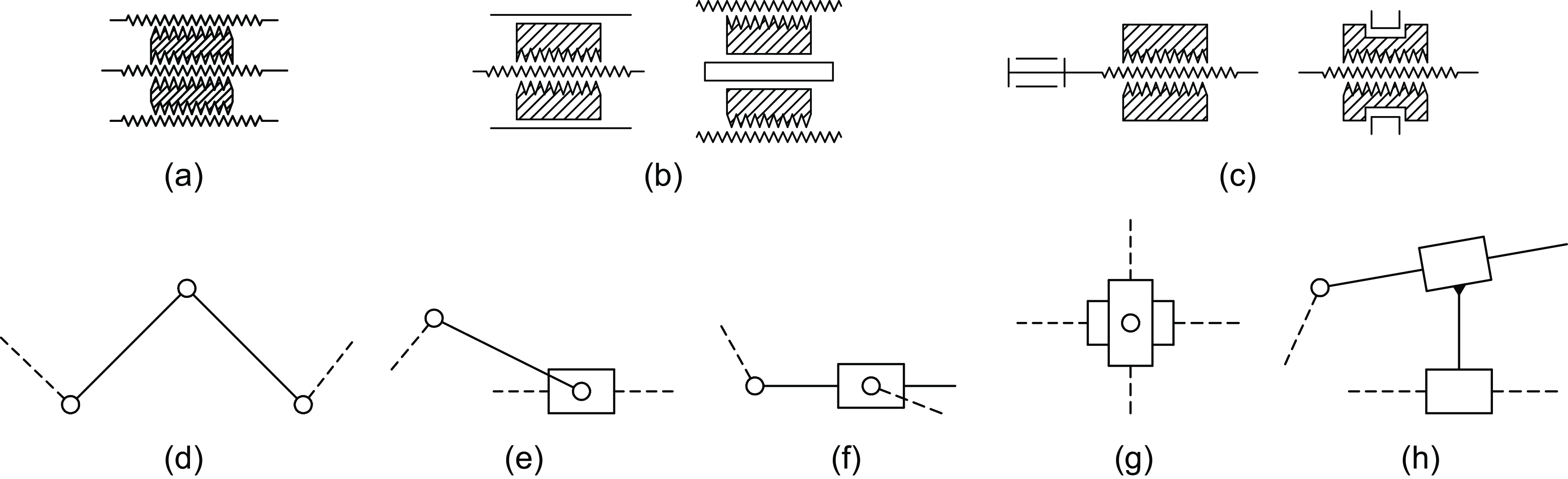
The cylindrical chain of the mechanism shown in Figure 2a has an inactive freedom (rotation). Similarly, there is an inactive freedom (translation) in the cylindrical chain in Figure 2b. As a result, the mechanisms illustrated in Figure 2 are planar because all their links perform planar motion. To generate spatial lever-screw mechanisms, we can change the structure of the cylindrical chain. The simplest way to do this is to represent this chain as a screw monad (a one-link group with zero DOFs). There are three ways of such representation [Reference Li, Hervé and Ye10, sec. 4.3]:
-
1. Using two helical joints with collinear axes and distinct pitches (Figure 3a).
-
2. Using one helical joint and one prismatic joint with parallel axes (Figure 3b).
-
3. Using one helical joint and one revolute joint with collinear axes (Figure 3c).
The simplest screw and planar zero-DOF groups: (a)–(c) screw monads HH, HP (PH), and RH (HR); (d)–(h) planar dyads RRR, RRP, RPR, PRP, and RPP (notations R, P, and H indicate revolute, prismatic, and helical joints, respectively).

We will also use the simplest representation of planar chains—planar dyads (two-link groups with zero DOFs) depicted in Figures 3d–h. Now, if we combine any of these monads and dyads, we obtain five-bar lever-screw mechanisms where some links perform spatial screw-type motions. In paper [Reference Fomin and Antonov21], we considered all possible combinations and illustrated a large number of novel mechanisms.
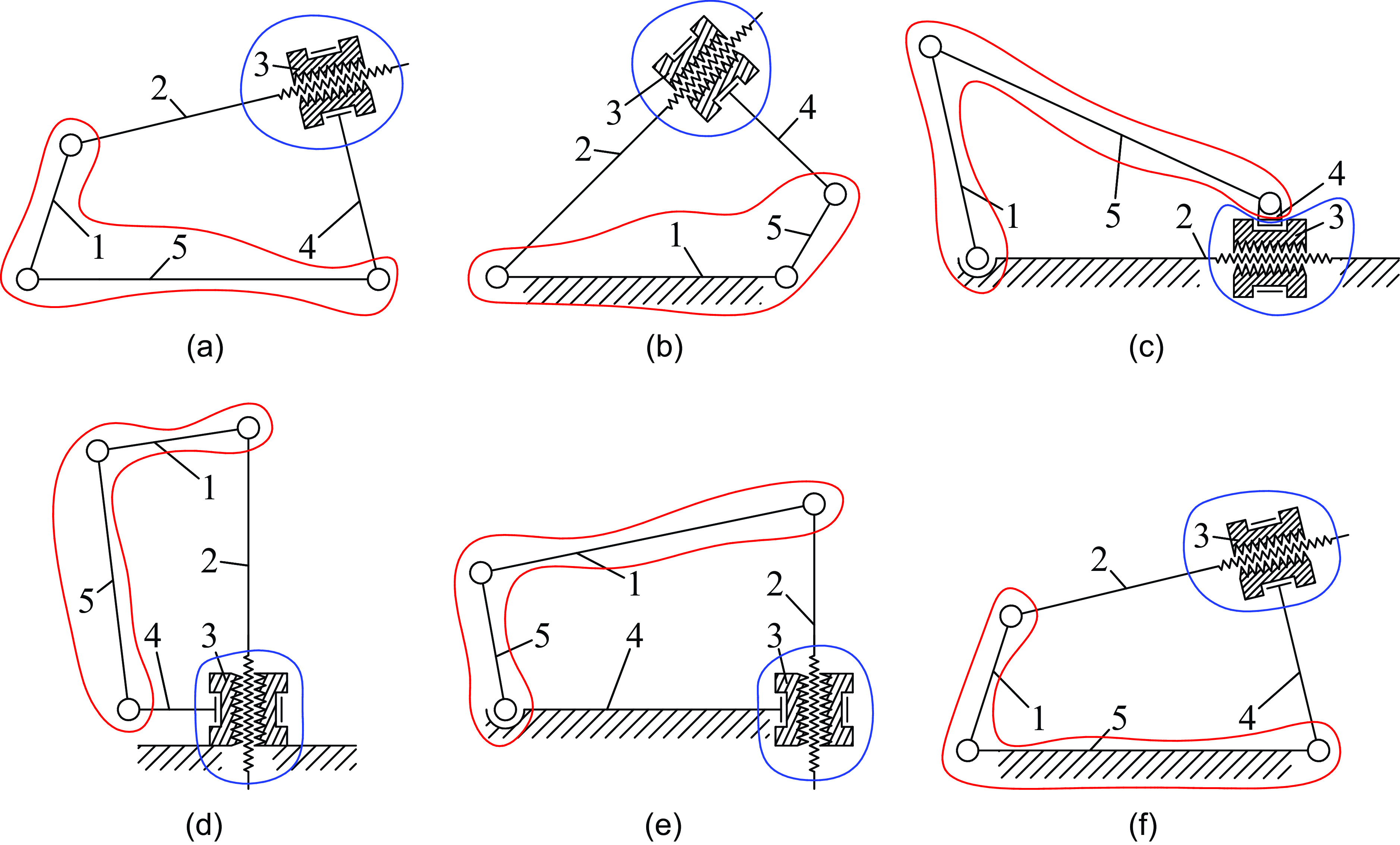
To design 4R1H mechanisms, we couple an HR monad (Figure 3c) with an RRR dyad (Figure 3d) along the common translational motion (Figure 2a). Figure 4a demonstrates a five-bar closed-loop chain developed this way. We can choose any link in this chain as a base and get five different mechanisms. Figures 4b–f show all these mechanisms derived from the closed-loop chain by fixing link 1, …, 5, respectively.
4R1H closed-loop kinematic chain (a) and 1-DOF mechanisms (b)–(f) obtained by combining an RRR planar dyad (red) and an HR screw monad (blue) along the common translational motion.

Among the synthesized mechanisms, the ones illustrated in Figures 4b and 4f look most attractive for further analysis. If we consider nut 3 as the output link, we see its points follow screw-like trajectories around the curvilinear axis. This feature distinguishes these mechanisms from other screw-type mechanisms where this axis remains straight. Mechanisms with curvilinear axes of screw-like trajectories can be applied for mixing or processing operations where the output link should follow a complex spatial path [Reference Fomin and Ivanov20].
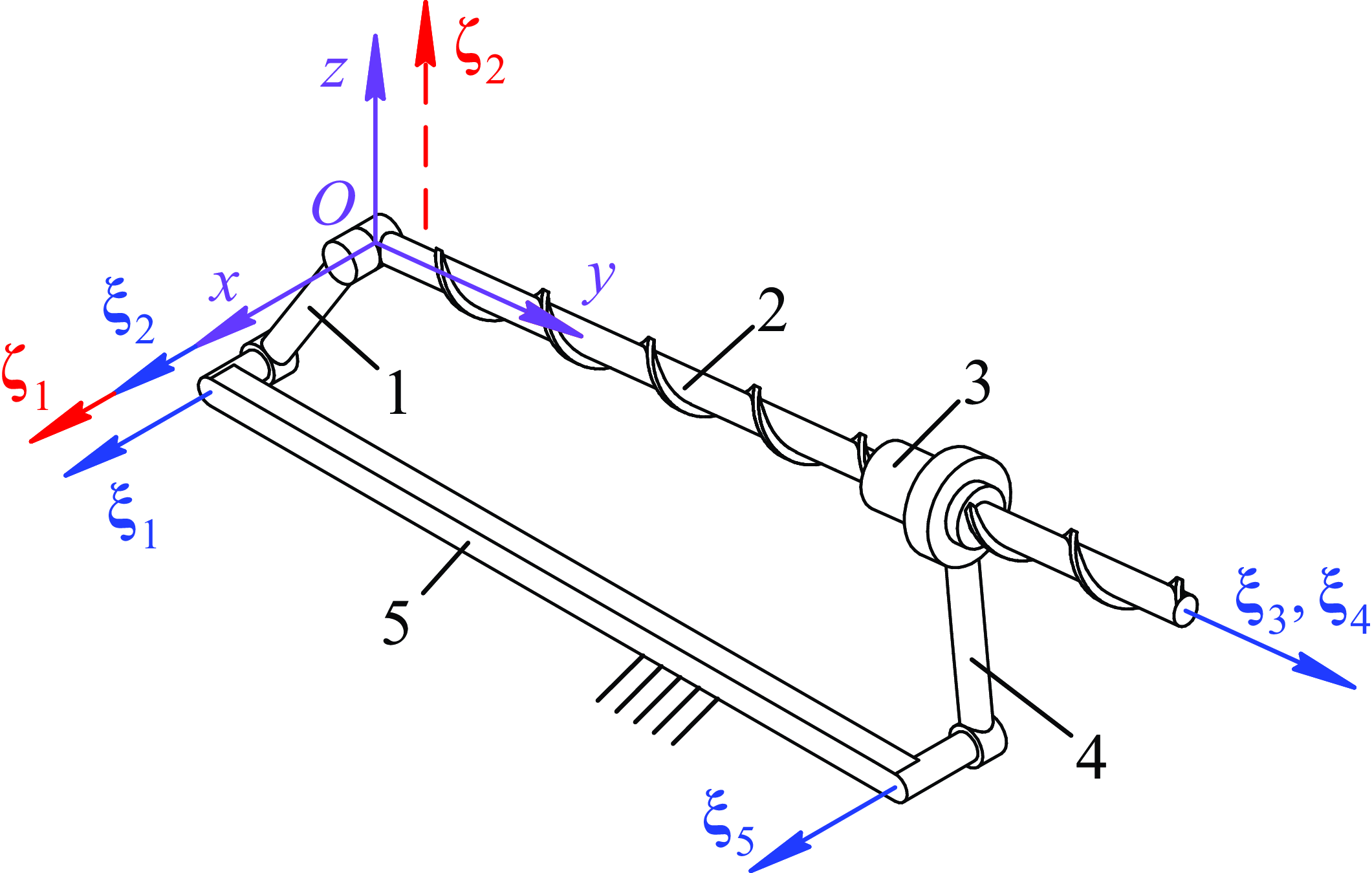
In view of the above, the subsequent research will focus on the 4R1H mechanism depicted in Figure 4f, but we can adapt the proposed techniques to other 4R1H mechanisms as well. The mechanism consists of the following links: crank 1 (input link), screw-type coupler 2, nut 3 (output link), rocker 4, and base 5. In the next sections, we will perform a comprehensive study of this mechanism, including its mobility, singularity, kinematic, and dynamic analysis.
3. Mobility Analysis
The mobility analysis of the mechanism serves multiple purposes. First, it aims to verify the results of the type synthesis and prove that the mechanism indeed has one DOF. Second, it helps us identify the motion type of the output link and check if this type changes during the mechanism operation. Finally, the mobility analysis represents the basis for detecting singular configurations.
In this section, we will consider the first two problems listed above, while the singularities will be covered in Section 4. To solve these problems, we will follow the same procedure we applied in paper [Reference Fomin, Antonov, Glazunov, Filippov and Okada22] when we studied another 4R1H mechanism. We consider (unit) twists
 ${\unicode{x1D6CF}}_1, \dots, {\unicode{x1D6CF}}_5$
associated with the mechanism joints (Figure 5). These twists have the following coordinates in reference frame
 $Oxyz$
placed according to Figure 5:
 \begin{align} \begin{gathered} {\unicode{x1D6CF}}_1 = \left[\begin{array}{l@{\quad}l@{\quad}l@{\quad}l@{\quad}l@{\quad}l} 1 & 0 & 0 & 0 & a_1 & b_1 \end{array} \right]^{\mathrm{T}}, \quad {\unicode{x1D6CF}}_2 = \left[\begin{array}{l@{\quad}l@{\quad}l@{\quad}l@{\quad}l@{\quad}l} 1 & 0 & 0 & 0 & 0 & 0 \end{array}\right]^{\mathrm{T}}, \quad {\unicode{x1D6CF}}_3 = \left[\begin{array}{l@{\quad}l@{\quad}l@{\quad}l@{\quad}l@{\quad}l} 0 & 1 & 0 & 0 & p & 0 \end{array}\right]^{\mathrm{T}}, \\[3pt] {\unicode{x1D6CF}}_4 = \left[\begin{array}{l@{\quad}l@{\quad}l@{\quad}l@{\quad}l@{\quad}l} 0 & 1 & 0 & 0 & 0 & 0 \end{array}\right]^{\mathrm{T}}, \quad {\unicode{x1D6CF}}_5 = \left[\begin{array}{l@{\quad}l@{\quad}l@{\quad}l@{\quad}l@{\quad}l} 1 & 0 & 0 & 0 & a_5 & b_5 \end{array}\right]^{\mathrm{T}}, \end{gathered} \end{align}
where
 $a_1$
,
 $b_1$
,
 $a_5$
, and
 $b_5$
are nonzero parameters that depend on the mechanism geometry and its configuration;
 $p$
is a pitch of the H joint.
Twists and wrenches of the considered 4R1H mechanism. Solid and dashed lines indicate twists and wrenches with a finite and an infinite pitch, respectively. Links numbering corresponds to Figure 4f.

If we compose a matrix whose columns are the twists from Eq. (1), its third and fourth rows will be zero rows. Therefore, the matrix rank equals four, and there are only four linearly independent twists. It means the mechanism is overconstrained and has one DOF. To confirm this statement, we can look at the wrench system of the mechanism, which includes the wrenches reciprocal to twists
 ${\unicode{x1D6CF}}_1, \dots, {\unicode{x1D6CF}}_5$
. By simple observation [Reference Zhao, Li, Yang and Yu23], we find this system is spanned by two wrenches
 ${{\unicode{x1D6C7}}}_1$
and
 ${{\unicode{x1D6C7}}}_2$
:
 \begin{align}{{\unicode{x1D6C7}}}_1 = \left[\begin{array}{l@{\quad}l@{\quad}l@{\quad}l@{\quad}l@{\quad}l} 1 & 0 & 0 & 0 & 0 & 0 \end{array}\right]^{\mathrm{T}}, \quad{{\unicode{x1D6C7}}}_2 = \left[\begin{array}{l@{\quad}l@{\quad}l@{\quad}l@{\quad}l@{\quad}l} 0 & 0 & 0 & 0 & 0 & 1 \end{array}\right]^{\mathrm{T}}. \end{align}
Thus, in any nonsingular configuration, joint twists
 ${\unicode{x1D6CF}}_1, \dots, {\unicode{x1D6CF}}_5$
are reciprocal to zero-pitch wrench
 ${{\unicode{x1D6C7}}}_1$
and infinite-pitch wrench
 ${{\unicode{x1D6C7}}}_2$
. The axis of wrench
 ${{\unicode{x1D6C7}}}_1$
passes through point
 $O$
and remains parallel to the
 $Ox$
axis; the axis of wrench
 ${{\unicode{x1D6C7}}}_2$
remains parallel to the
 $Oz$
axis (Figure 5). This analysis shows the twists belong to a persistent four-system [Reference Carricato and Zlatanov24] (in particular, to the second special four-system [Reference Hunt5, ch. 12]), so we can compute mobility
 $M$
of the considered single-loop 4R1H mechanism as follows [Reference Carricato and Zlatanov24]:
 \begin{align} M = \sum _{i = 1}^{5} f_i - n = 5 - 4 = 1, \end{align}
where
 $f_i = 1$
is a number of DOFs of the
 $i$
-th joint,
 $i = 1, \dots, 5$
;
 $n = 4$
is a dimension of the twist system.
We can determine the motion type of the output link by analyzing its twist system. Since the mechanism has one DOF, this twist system is spanned by a single twist. We find this twist as the intersection of two linear subspaces:
 $\textrm{span}({\unicode{x1D6CF}}_1, {\unicode{x1D6CF}}_2, {\unicode{x1D6CF}}_3)$
and
 $\textrm{span}({\unicode{x1D6CF}}_4, {\unicode{x1D6CF}}_5)$
. Using the algorithm from paper [Reference Song, Kang and Dai25], implemented in Julia [Reference Bezanson, Edelman, Karpinski and Shah26] with the help of the Symbolics package [Reference Gowda, Ma, Cheli, Gwóźzdź, Shah, Edelman and Rackauckas27], we computed (non-unit) twist
 ${\unicode{x1D6CF}}$
, which spans the intersection:Footnote
1
 \begin{align} {\unicode{x1D6CF}} = \left[\begin{array}{l@{\quad}l@{\quad}l@{\quad}l@{\quad}l@{\quad}l} 1 & \dfrac{a_5b_1 - a_1b_5}{pb_1} & 0 & 0 & a_5 & b_5 \end{array}\right]^{\mathrm{T}}. \end{align}
Equation (4) shows that the output link performs a spatial motion. The first, fifth, and sixth components of twist
 ${\unicode{x1D6CF}}$
coincide with twist
 ${\unicode{x1D6CF}}_5$
and correspond to the rocker inclination. The second component corresponds to the output link rotation about the
 $Oy$
axis. Two special cases deserve attention:
-
1. When
$b_1 = 0$
, the crank is orthogonal to the coupler, and the second component of twist
${\unicode{x1D6CF}}$
tends to infinity. We can normalize twist
${\unicode{x1D6CF}}$
by this component and get:
${\unicode{x1D6CF}} = [0\,\,1\,\,0\,\,0\,\,0\,\,0]^{\mathrm{T}}$
. Thus, the instantaneous motion of the output link is a rotation about the
$Oy$
axis. In this configuration, the rocker changes the rotation direction. -
2. When
$a_5b_1 - a_1b_5 = 0$
, the crank is aligned with the base link, and the second component of twist
${\unicode{x1D6CF}}$
equals zero. Thus, we obtain
${\unicode{x1D6CF}} = {\unicode{x1D6CF}}_5$
: the instantaneous motion of the output link is a rotation about the rocker rotational axis. In this configuration, the output link changes its direction of rotation about the
$Oy$
axis.





This concludes the mobility analysis of the mechanism. In the next section, we will check if the mechanism meets any singular configurations during the motion.
4. Singularity analysis
Singularities represent configurations of the mechanism where its mobility can change [Reference Di Gregorio28]. Detecting these configurations is crucial to ensure that the mechanism functions correctly, and there are various methods to solve this problem [Reference Müller and Zlatanov29]. Here, we will use a screw theory approach and the results obtained in the previous section.
According to the preceding analysis, five joint twists
 ${\unicode{x1D6CF}}_1, \dots, {\unicode{x1D6CF}}_5$
are linearly dependent in a general (nonsingular) case, and the corresponding twist matrix has a rank equal to four. Equation (1) shows the third and fourth rows of this matrix are zeros, so we can write down
 $4 \times 5$
twist matrix
 $\mathbf{J}$
without these zero rows as follows:
 \begin{align} \mathbf{J} = \left[\begin{array}{l@{\quad}l@{\quad}l@{\quad}l@{\quad}l} 1 & 1 & 0 & 0 & 1 \\[3pt] 0 & 0 & 1 & 1 & 0 \\[3pt] a_1 & 0 & p & 0 & a_5 \\[3pt] b_1 & 0 & 0 & 0 & b_5 \end{array}\right]. \end{align}
Four rows of matrix
 $\mathbf{J}$
are linearly independent in a general case; therefore,
 ${\textrm{rank}}(\mathbf{J}) = 4$
, and the mechanism has one DOF. The mechanism will be in a singular configuration and gain additional DOFs if and only if
 ${\textrm{rank}}(\mathbf{J}) \lt 4$
. We can check this condition by analyzing the minors (determinants of square submatrices) of matrix
 $\mathbf{J}$
. By looking at the first three rows and the three middle columns of matrix
 $\mathbf{J}$
, we see that there always exist nonzero minors of the 1st, 2nd, and 3rd order (
 $p \neq 0$
according to the mechanism design). Thus,
 ${\textrm{rank}}(\mathbf{J}) \geq 3$
, and we should only check if the rank of matrix
 $\mathbf{J}$
equals three. To solve this problem, we consider the minors of the 4th order. Let
 $M_i$
,
 $i = 1, \dots, 5$
, be the minor computed after deleting the
 $i$
-th column of matrix
 $\mathbf{J}$
. From Eq. (5), we get:
 \begin{align} M_1 = -pb_5, \qquad M_2 = pb_1 - pb_5, \qquad M_3 = M_4 = a_1 b_5 - a_5 b_1, \qquad M_5 = b_1. \end{align}
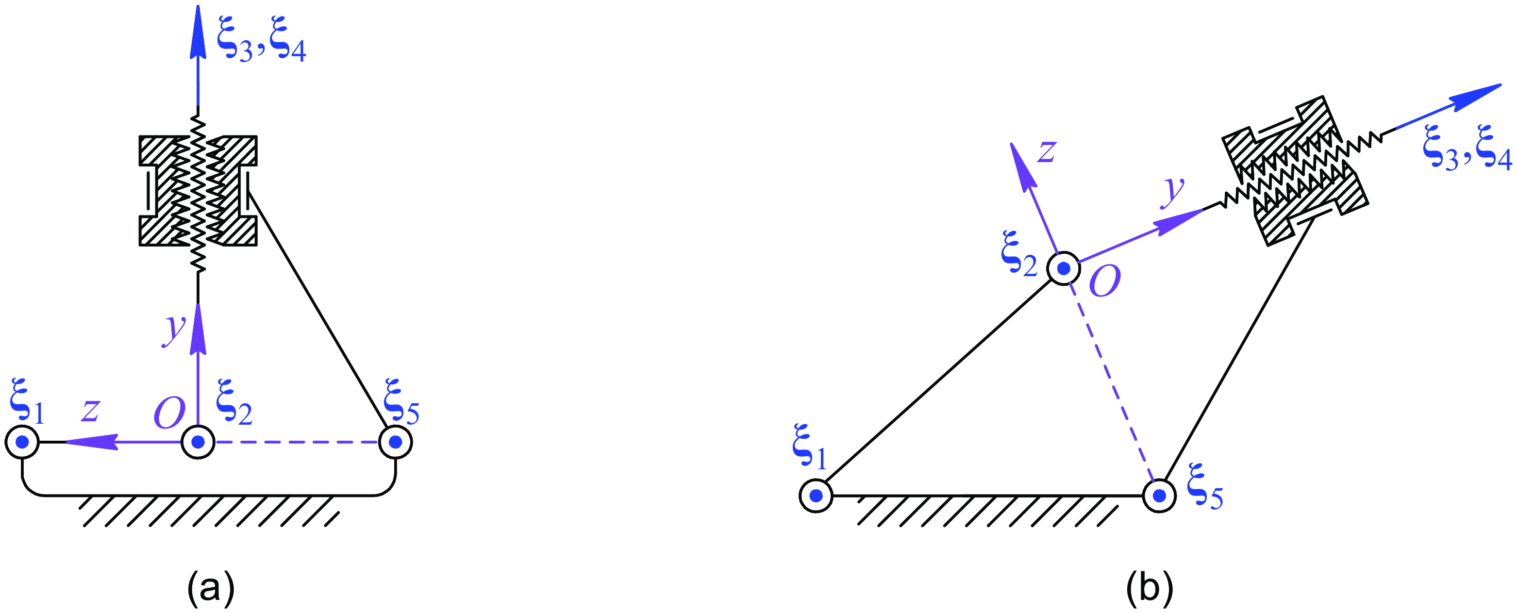
Singularities of the 4R1H mechanism: (a) two DOFs when the crank is aligned with the base and orthogonal to the coupler; (b) one uncontrollable DOF when the
 $Oz$
axis intersects the axis of
 ${\unicode{x1D6CF}}_5$
.

Since
 $p \neq 0$
, Eq. (6) shows that all minors become equal to zero when
 $b_1 = b_5 = 0$
, disregarding the values of parameters
 $a_1$
and
 $a_5$
. In this case, the
 $Oz$
axis intersects the rotational axes of both the crank and the rocker. It is possible only when the crank is aligned with the base and orthogonal to the coupler (Figure 6a). This is indeed a singular configuration of the 4R1H mechanism where it has two DOFs, and we can explain it as follows. Note that linear subspace
 $\textrm{span}({\unicode{x1D6CF}}_3, {\unicode{x1D6CF}}_4)$
always includes an infinite-pitch twist. In the considered configuration, the direction of this twist is orthogonal to the (parallel) axes of zero-pitch twists
 ${\unicode{x1D6CF}}_1$
,
 ${\unicode{x1D6CF}}_2$
, and
 ${\unicode{x1D6CF}}_5$
. All these zero- and infinite-pitch twists belong to the second special two-system [Reference Hunt5, ch. 12], so there are only two linearly independent twists among them. This confirms that the mechanism has an extra DOF in this configuration. In practice, we can easily avoid this singularity with a proper design of the mechanism. For example, if the rocker is orthogonal to the coupler, like in Figure 5, the mechanism will never meet this singular configuration. (With such a design, this singularity will only be possible when both the crank and the rocker are aligned with the base, but the mechanism will not be workable in this case.)
To finish the singularity analysis, we should check if the actuated joint is chosen properly. This can be done by eliminating twist
 ${\unicode{x1D6CF}}_1$
from the mechanism twist system and verifying that remaining twists
 ${\unicode{x1D6CF}}_2, \dots, {\unicode{x1D6CF}}_5$
are linearly independent. According to Eq. (1), the rank of the matrix whose columns are twists
 ${\unicode{x1D6CF}}_2, \dots, {\unicode{x1D6CF}}_5$
is equal to four in a general (nonsingular) configuration, so they are indeed linearly independent. Therefore, the mechanism remains motionless when its crank is locked. This confirms the proper selection of the actuated joint. We can also check when twists
 ${\unicode{x1D6CF}}_2, \dots, {\unicode{x1D6CF}}_5$
become dependent following the same approach that we applied above. We compose
 $4 \times 4$
matrix
 $\mathbf{J}'$
, which coincides with the last four columns of matrix
 $\mathbf{J}$
in Eq. (5). The twists become linearly dependent if and only if
 $\det (\mathbf{J}') = M_1 = 0$
. According to Eq. (6), this condition happens when
 $b_5 = 0$
, i.e., when the
 $Oz$
axis intersects the rocker rotational axis (Figure 6b). Unlike the configuration discussed earlier, the crank is not necessarily aligned with the base. The mechanism gains one uncontrollable degree of freedom in this singular configuration. Indeed, similar to the singular configuration discussed earlier, zero-pitch twists
 ${\unicode{x1D6CF}}_2$
and
 ${\unicode{x1D6CF}}_5$
and an infinite-pitch twist from linear subspace
 $\textrm{span}({\unicode{x1D6CF}}_3, {\unicode{x1D6CF}}_4)$
belong to the second special two-system, so there are only two linearly independent twists among them. This confirms that the mechanism achieves uncontrollable freedom. When designing the mechanism, we should select its geometrical parameters that guarantee the mechanism does not meet this singularity along the whole rotation cycle of the crank. Section 7 will illustrate the design of such a mechanism.
5. Kinematic analysis
The kinematic analysis aims to express the motion of the output link in terms of the input motion of the crank. This analysis is important for several reasons. For example, it can be used for the dimensional synthesis (geometric design), when it is necessary to select geometrical parameters of the mechanism for the specified trajectory of its output link [Reference McCarthy and Soh30, Reference Pathak, Singh, Sharma, Kumar and Chakraborty31]. Results of the kinematic analysis also represent the foundation for subsequent dynamic analysis, and we will use them in Section 6.
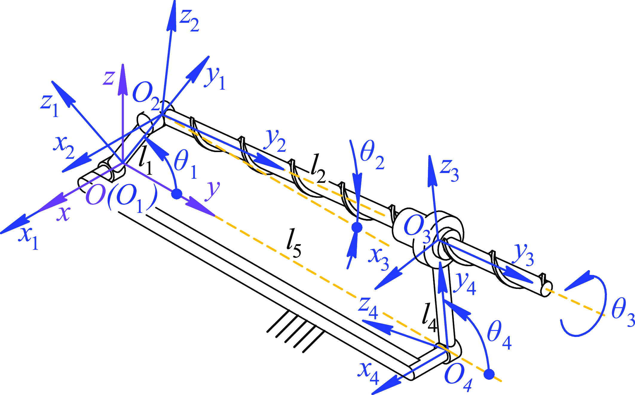
As we have shown in Section 3, the 1-DOF motion of the output link combines its rotation with the rocker and rotation about the screw axis. Let
 $\theta _4$
be the rocker angle of rotation and
 $\theta _3$
be the nut angle of rotation relative to the rocker (Figure 7). In addition, let
 $\omega _4$
,
 $\omega _3$
,
 $\varepsilon _4$
, and
 $\varepsilon _3$
be the first and second time derivatives of the corresponding angles (angular speeds and angular accelerations). The input motion of the crank can be described by its angle of rotation
 $\theta _1$
, angular speed
 $\omega _1$
, and angular acceleration
 $\varepsilon _1$
. Thus, the goal of the kinematic analysis is to express parameters
 $\theta _3$
,
 $\theta _4$
,
 $\omega _3$
,
 $\omega _4$
,
 $\varepsilon _3$
, and
 $\varepsilon _4$
in terms of
 $\theta _1$
,
 $\omega _1$
, and
 $\varepsilon _1$
.
Rotation angles and reference frames of the links.

5.1. Position analysis
We start with the position analysis and attach reference frame
 $Oxyz$
to the base link according to Figure 7. Next, we can consider the vector-loop equation of the mechanism and examine its projections onto the
 $Oy$
and
 $Oz$
axes:
 \begin{align} \begin{cases} l_1 \cos (\theta _1) + l_2 \cos (\theta _2) - l_4 \cos (\theta _4) = l_5, \\[3pt] l_1 \sin (\theta _1) + l_2 \sin (\theta _2) - l_4 \sin (\theta _4) = 0, \end{cases} \end{align}
where
 $\theta _2$
is an angle between the screw axis and the
 $Oy$
axis;
 $l_1$
,
 $l_4$
, and
 $l_5$
are constant lengths of the crank, the rocker, and the base, respectively;
 $l_2$
is a variable length of the coupler.
In addition, we have the following relation between angles
 $\theta _2$
and
 $\theta _4$
(Figure 7):
 \begin{align} \theta _4 = \theta _2 + \pi / 2. \end{align}
Using Eq. (8), we can eliminate angle
 $\theta _2$
and rewrite Eq. (7) as follows:
 \begin{align} l_1 \cos (\theta _1) + l_2 \sin (\theta _4) - l_4 \cos (\theta _4) = l_5, \\[-25pt]\nonumber\end{align}
 \begin{align} l_1 \sin (\theta _1) - l_2 \cos (\theta _4) - l_4 \sin (\theta _4) = 0. \end{align}
Equations (9) includes two unknown parameters: length
 $l_2$
and angle
 $\theta _4$
. To find the latter, we multiply both sides of Eq. (9a) by
 $\cos (\theta _4)$
and both sides of Eq. (9b) by
 $\sin (\theta _4)$
. Summing up the resulting equations, we get:
 \begin{align} (l_1 \cos (\theta _1) - l_5) \cos (\theta _4) + l_1 \sin (\theta _1) \sin (\theta _4) - l_4 = 0. \end{align}
Equation (10) is a trigonometric equation with respect to single variable
 $\theta _4$
whose solutions have the following form [Reference Waldron, Schmiedeler, Siciliano and Khatib32, sec. 2.7]:
 \begin{align} \theta _4 = 2{\textrm{atan}}\left (\dfrac{C_2 \pm \sqrt{C_1^2 + C_2^2 - C_3^2}}{C_1 - C_3}\right ), \end{align}
with coefficients
 $C_1$
,
 $C_2$
, and
 $C_3$
deduced from Eq. (10):
 \begin{equation*} C_1 = l_1 \cos (\theta _1) - l_5, \qquad C_2 = l_1 \sin (\theta _1), \qquad C_3 = -l_4. \end{equation*}
The “
 $\pm$
” sign in Eq. (11) corresponds to two different solutions and two different assembly modes of the mechanism. We select a suitable solution according to the mechanism geometry and operating conditions. To find remaining angle
 $\theta _3$
, we have to compute length
 $l_2$
first. This time, we multiply both sides of Eq. (9a) by
 $\sin (\theta _4)$
and both sides of Eq. (9b) by
 $\cos (\theta _4)$
. Subtracting the resulting equations from each other, we get:
 \begin{align} l_2 = l_1 \sin (\theta _1 - \theta _4) + l_5 \sin (\theta _4). \end{align}
Finally, we calculate angle
 $\theta _3$
using the expression below:
 \begin{align} \theta _3 = 2\pi (l_2 - l_2^0) / p, \end{align}
where
 $l_2^0$
is a value of
 $l_2$
for
 $\theta _1 = 0$
, which we can determine using Eqs. (11) and (12). For the considered mechanism (Figure 7), we have
 $l_2^0 = ((l_5 - l_1)^2 - l_4^2)^{1/2}$
.
We have found all the parameters that describe the configuration of the output link. In the dynamic analysis (Section 6), we will also need the value of angle
 $\theta _2$
, which we can determine from Eq. (8). This completes the position analysis of the mechanism.
5.2. Velocity analysis
Velocity analysis of the mechanism is the next step. We can find angular speed
 $\omega _4$
by taking the time derivative of Eq. (10). After rearranging the terms in the resulting equation, we get:
 \begin{align} l_2 \omega _4 - l_1 \omega _1 \sin (\theta _1 - \theta _4) = 0, \end{align}
from where we can express angular speed
 $\omega _4$
.
To find angular speed
 $\omega _3$
, we differentiate Eq. (13) with respect to time:
 \begin{align} \omega _3 = 2\pi \upsilon _2 / p, \end{align}
where
 $\upsilon _2$
is a time derivative of length
 $l_2$
, which comes from Eq. (12):
 \begin{align} \upsilon _2 = l_1 (\omega _1 - \omega _4) \cos (\theta _1 - \theta _4) + l_5 \omega _4 \cos (\theta _4). \end{align}
During the dynamic analysis, we will need angular speed
 $\omega _2$
of the coupler. From Eq. (8), we get
 $\omega _2 = \omega _4$
. This completes the velocity analysis of the mechanism.
5.3. Acceleration analysis
We finish the kinematic analysis of the mechanism by computing accelerations of its links. Differentiating Eq. (14) with respect to time, we obtain angular acceleration
 $\varepsilon _4$
of the rocker:
 \begin{align} \varepsilon _4 = \left(l_1 \left(\varepsilon _1 \sin (\theta _1 - \theta _4) + \omega _1 (\omega _1 - \omega _4) \cos (\theta _1 - \theta _4)\right) - \upsilon _2 \omega _4\right) / l_2. \end{align}
Next, we compute angular acceleration
 $\varepsilon _3$
by taking a time derivative of Eq. (15):
 \begin{align} \varepsilon _3 = 2\pi a_2 / p, \end{align}
where
 $a_2$
is a time derivative of speed
 $\upsilon _2$
, which we find from Eq. (16):
 \begin{align} a_2 = l_1 \left((\varepsilon _1 - \varepsilon _4) \cos (\theta _1 - \theta _4) - (\omega _1 - \omega _4)^2 \sin (\theta _1 - \theta _4)\right) + l_5 \left(\varepsilon _4 \cos (\theta _4) - \omega _4^2 \sin (\theta _4)\right). \end{align}
Finally, we compute angular acceleration
 $\varepsilon _2$
of the coupler, which is equal to angular acceleration
 $\varepsilon _4$
of the rocker, i.e.,
 $\varepsilon _2 = \varepsilon _4$
. Thus, we have expressed positions, angular speeds, and angular accelerations of all the links in terms of the crank motion defined by parameters
 $\theta _1$
,
 $\omega _1$
, and
 $\varepsilon _1$
. This completes the kinematic analysis of the 4R1H mechanism.
6. Dynamic analysis
The dynamic analysis presented in this section aims to compute the motor torque required to perform the desired motion (i.e., we solve the inverse dynamic problem [Reference Wang, Li and Sun33]). This is necessary for a proper selection of the motor and development of a physical prototype of the mechanism, which we will consider in Section 7. In the following computations, we assume all the links are rigid and all the joints are frictionless. We ignore friction effects because of their complicated nature, as we will discuss in Section 8. In practice, we can reduce friction effects by lubricating the joints appropriately.
To model the mechanism dynamics, we will employ Kane’s method [Reference Roithmayr and Hodges34]. Unlike the Newton–Euler or Lagrange equations, this method does not need to consider internal joint reactions or differentiate energy functions. Numerous studies have successfully applied Kane’s method to various mechanisms [Reference Feng, Zhang, Li and Baoyin35–Reference Cheng, Yuan, Yang, Luo, Zeng and Zhang38], and here we will adapt it for the considered 4R1H mechanism. Although three of the four moving links perform planar motion, we will consider the equations of spatial motion to make our presentation consistent. Work [Reference Roithmayr and Hodges34] is a primary reference for subsequent formulations and terminology.
6.1. Problem formulation
Kane’s method requires selecting generalized speeds of the mechanism. The considered mechanism has a single DOF, and it is natural to choose angular speed
 $\omega _1$
of the crank as the generalized speed. Thus, there will be only one equation of motion, which has the following form:
 \begin{align} F + F^\star = 0, \end{align}
where
 $F$
and
 $F^\star$
are the generalized active and inertia forces, respectively, corresponding to generalized speed
 $\omega _1$
.
Let
 $i = 1, \dots, 4$
be an index number of a moving link according to Figure 5. Suppose the
 $i$
-th link is affected by a set of active forces and torques. We can reduce these forces and torques to resultant force
 $\mathbf{F}_i$
, whose axis passes through center of mass (COM)
 $C_i$
, and resultant torque
 $\mathbf{T}_i$
. Given the above, we can calculate generalized forces
 $F$
and
 $F^\star$
in the following way:
 \begin{align} F &= \sum _{i = 1}^{4} \left (\boldsymbol{\unicode{x03C5}}_{\omega 1}^{Ci} \cdot \mathbf{F}_i + \boldsymbol{\unicode{x03C9}}_{\omega 1}^i \cdot \mathbf{T}_i \right ), \\[-27pt] \nonumber \end{align}
 \begin{align} F^\star &= \sum _{i = 1}^{4} \left (\boldsymbol{\unicode{x03C5}}_{\omega 1}^{Ci} \cdot \mathbf{F}_i^\star + \boldsymbol{\unicode{x03C9}}_{\omega 1}^i \cdot \mathbf{T}_i^\star \right ), \end{align}
where
 $\mathbf{F}_i^\star$
is an inertia force acting on the
 $i$
-th link in its COM;
 $\mathbf{T}_i^\star$
is an inertia torque acting on the
 $i$
-th link;
 $\boldsymbol{\unicode{x03C5}}_{\omega 1}^{Ci}$
is a partial velocity of point
 $C_i$
;
 $\boldsymbol{\unicode{x03C9}}_{\omega 1}^i$
is a partial angular velocity of the
 $i$
-th link.Footnote
2
We suppose all vector variables are written with respect to the same reference frame.
We compute inertia force
 $\mathbf{F}_i^\star$
and inertia torque
 $\mathbf{T}_i^\star$
acting on the
 $i$
-th link from the following relations:
 \begin{align} \mathbf{F}_i^\star &= -m_i \mathbf{a}_{Ci}, \\[-27pt] \nonumber \end{align}
 \begin{align} \mathbf{T}_i^\star &= -\mathbf{I}_{Ci} \boldsymbol{\unicode{x025B}}_i - \boldsymbol{\unicode{x03C9}}_i \times \mathbf{I}_{Ci}\boldsymbol{\unicode{x03C9}}_i, \end{align}
where
 $\mathbf{a}_{Ci}$
is an acceleration of the
 $i$
-th link COM;
 $\boldsymbol{\unicode{x03C9}}_i$
and
 $\boldsymbol{\unicode{x025B}}_i$
are angular velocity and acceleration of the
 $i$
-th link;
 $m_i$
is a mass of the
 $i$
-th link;
 $\mathbf{I}_{Ci}$
is an inertia matrix of the
 $i$
-th link about its COM.
Partial velocity
 $\boldsymbol{\unicode{x03C5}}_{\omega 1}^{Ci}$
and partial angular velocity
 $\boldsymbol{\unicode{x03C9}}_{\omega 1}^i$
are partial derivatives of velocity
 $\boldsymbol{\unicode{x03C5}}_{Ci}$
of point
 $C_i$
and angular velocity
 $\boldsymbol{\unicode{x03C9}}_i$
with respect to generalized speed
 $\omega _1$
:
 \begin{align} \boldsymbol{\unicode{x03C5}}_{\omega 1}^{Ci} = \frac{\partial \boldsymbol{\unicode{x03C5}}_{Ci}}{\partial \omega _1}, \quad \boldsymbol{\unicode{x03C9}}_{\omega 1}^{i} = \frac{\partial \boldsymbol{\unicode{x03C9}}_i}{\partial \omega _1}. \end{align}
To summarize, we should compute the following parameters to derive Eq. (20):
-
1. Angular velocities and angular accelerations of the links.
-
2. Accelerations of their COMs.
-
3. Partial velocities of the COMs and partial angular velocities of the links.
-
4. Inertia matrices.
-
5. Active forces and torques.
The next subsection will show that we can compute the parameters listed above with almost no effort using the kinematic expressions from Section 5.
6.2. Kinematic and dynamic parameters
As mentioned in the previous subsection, we consider all the vector parameters are expressed in the same reference frame. Without loss of generality, we select base frame
 $Oxyz$
as this reference frame. To make the subsequent analysis more convenient, we also attach reference frame
 $O_ix_iy_iz_i$
to the
 $i$
-th link,
 $i = 1, \dots, 4$
, according to Figure 7. Frame
 $O_3x_3y_3z_3$
of the output link is attached in such a way that the
 $O_3x_3$
axis is parallel to the
 $Ox$
axis of the base frame when
 $\theta _1 = 0$
. Rotation matrices
 $\mathbf{R}_i$
describe orientation of frames
 $O_ix_iy_iz_i$
relative to
 $Oxyz$
, and we calculate these matrices as follows:
 \begin{align} \mathbf{R}_i = \mathbf{R}_x(\theta _i), \quad i = 1, 2, 4, \qquad \mathbf{R}_3 = \mathbf{R}_2 \mathbf{R}_y(\theta _3), \end{align}
where
 $\mathbf{R}_x(\ast )$
and
 $\mathbf{R}_y(\ast )$
are the matrices of elementary rotations about the corresponding axes [Reference Waldron, Schmiedeler, Siciliano and Khatib32, sec. 2.2]. Angles
 $\theta _i$
,
 $i = 2, 3, 4$
, are determined according to Eqs. (8), (11), and (13) we derived in Subsection 5.1. We are now ready to compute all the parameters required for the dynamic analysis.
6.2.1. Angular velocities and angular accelerations
We start with calculating angular velocities
 $\boldsymbol{\unicode{x03C9}}_i$
,
 $i = 1, \dots, 4$
. Let
 $\hat{\mathbf{x}} = [1\,0\,0]^{\mathrm{T}}$
be a unit vector parallel to the
 $Ox$
axis of frame
 $Oxyz$
. Using this notation, we can write:
 \begin{align} \boldsymbol{\unicode{x03C9}}_i = \omega _i \hat{\mathbf{x}}, \quad i = 1, 2, 4, \qquad \boldsymbol{\unicode{x03C9}}_3 = \boldsymbol{\unicode{x03C9}}_2 + \omega _3 \hat{\mathbf{y}}_2, \end{align}
where
 $\hat{\mathbf{y}}_2$
is a unit vector equal to the second column of rotation matrix
 $\mathbf{R}_2$
. Angular speeds
 $\omega _i$
,
 $i = 2, 3, 4$
, can be found from Eqs. (14) and (15) given in Subsection 5.2.
Next, we compute angular accelerations
 $\boldsymbol{\unicode{x025B}}_i$
using Eq. (25):
 \begin{align} \boldsymbol{\unicode{x025B}}_i = \varepsilon _i \hat{\mathbf{x}}, \quad i = 1, 2, 4, \qquad \boldsymbol{\unicode{x025B}}_3 = \boldsymbol{\unicode{x025B}}_2 + \varepsilon _3 \hat{\mathbf{y}}_2 + \omega _2 \omega _3 \hat{\mathbf{z}}_2, \end{align}
where
 $\hat{\mathbf{z}}_2$
is a unit vector equal to the third column of rotation matrix
 $\mathbf{R}_2$
. To get Eq. (26), we have used condition
 $\dot{\hat{\mathbf{y}}}_2 = \mathbf{\boldsymbol{\unicode{x03C9}}}_2 \times \hat{\mathbf{y}}_2 = \omega _2 \hat{\mathbf{z}}_2$
. Angular accelerations
 $\varepsilon _i$
,
 $i = 2, 3, 4$
, come from Eqs. (17) and (18) derived in Subsection 5.3.
6.2.2. Accelerations of COMs
Let vector
 $\mathbf{r}_{Ci}$
define the COM coordinates of the
 $i$
-th link in its reference frame
 $O_ix_iy_iz_i$
. This is a constant parameter that depends on the link geometry and its mass distribution. Vector
 $\mathbf{p}_{OiCi} = \mathbf{R}_i \mathbf{r}_{Ci}$
represents these coordinates relative to base frame
 $Oxyz$
. Given these notations, we compute acceleration
 $\mathbf{a}_{Ci}$
of the COM as follows:
 \begin{align} \mathbf{a}_{Ci} = \mathbf{a}_{Oi} + \boldsymbol{\unicode{x025B}}_i \times \mathbf{p}_{OiCi} + \boldsymbol{\unicode{x03C9}}_i \times (\boldsymbol{\unicode{x03C9}}_i \times \mathbf{p}_{OiCi}), \end{align}
where
 $\mathbf{a}_{Oi}$
is an acceleration of point
 $O_i$
:
 \begin{align} \begin{aligned} \mathbf{a}_{O1} &= \mathbf{a}_{O4} = \mathbf{0}, \\[3pt] \mathbf{a}_{O2} &= \boldsymbol{\unicode{x025B}}_1 \times \mathbf{p}_{O1O2} + \boldsymbol{\unicode{x03C9}}_1 \times (\boldsymbol{\unicode{x03C9}}_1 \times \mathbf{p}_{O1O2}), \\[3pt] \mathbf{a}_{O3} &= \boldsymbol{\unicode{x025B}}_4 \times \mathbf{p}_{O4O3} + \boldsymbol{\unicode{x03C9}}_4 \times (\boldsymbol{\unicode{x03C9}}_4 \times \mathbf{p}_{O4O3}), \end{aligned} \end{align}
with
 $\mathbf{p}_{O1O2}$
and
 $\mathbf{p}_{O4O3}$
being the vectors directed from point
 $O_1$
to
 $O_2$
and from point
 $O_4$
to
 $O_3$
, respectively. We determine these vectors according to Figure 7:
 \begin{align} \mathbf{p}_{O1O2} = \mathbf{R}_1 \left[\begin{array}{l@{\quad}l@{\quad}l} 0 & l_1 & 0 \end{array}\right]^{\mathrm{T}}, \qquad \mathbf{p}_{O4O3} = \mathbf{R}_4 \left[\begin{array}{l@{\quad}l@{\quad}l} 0 & l_4 & 0 \end{array} \right]^{\mathrm{T}}. \end{align}
6.2.3. Partial velocities of COMs and partial angular velocities
We begin with computing partial angular velocities
 $\boldsymbol{\unicode{x03C9}}_{\omega 1}^i$
,
 $i = 1, \dots, 4$
. Using Eq. (25) together with Eqs. (14)–(16), we get:
 \begin{align} \begin{aligned} \boldsymbol{\unicode{x03C9}}_{\omega 1}^1 &= \hat{\mathbf{x}}, \\[3pt] \boldsymbol{\unicode{x03C9}}_{\omega 1}^2 &= \boldsymbol{\unicode{x03C9}}_{\omega 1}^4 = \dfrac{l_1 \sin (\theta _1 - \theta _4)}{l_2} \hat{\mathbf{x}}, \\[3pt] \boldsymbol{\unicode{x03C9}}_{\omega 1}^3 &= \boldsymbol{\unicode{x03C9}}_{\omega 1}^2 + \dfrac{2\pi l_1}{p} \left (\cos (\theta _1 - \theta _4) - \dfrac{\left(l_1 \cos (\theta _1 - \theta _4) - l_5 \cos (\theta _4)\right) \sin (\theta _1 - \theta _4)}{l_2}\right ) \hat{\mathbf{y}}_2. \end{aligned} \end{align}
To find partial velocity
 $\boldsymbol{\unicode{x03C5}}_{\omega 1}^{Ci}$
of the
 $i$
-th link COM, we can first write velocity
 $\boldsymbol{\unicode{x03C5}}_{Ci}$
of point
 $C_i$
:
 \begin{align} \boldsymbol{\unicode{x03C5}}_{Ci} = \boldsymbol{\unicode{x03C5}}_{Oi} + \boldsymbol{\unicode{x03C9}}_i \times \mathbf{p}_{OiCi}, \end{align}
where
 $\boldsymbol{\unicode{x03C5}}_{Oi}$
is a velocity of point
 $O_i$
:
 \begin{align} \boldsymbol{\unicode{x03C5}}_{O1} = \boldsymbol{\unicode{x03C5}}_{O4} = \mathbf{0}, \qquad \boldsymbol{\unicode{x03C5}}_{O2} = \boldsymbol{\unicode{x03C9}}_1 \times \mathbf{p}_{O1O2}, \qquad \boldsymbol{\unicode{x03C5}}_{O3} = \boldsymbol{\unicode{x03C9}}_4 \times \mathbf{p}_{O4O3}. \end{align}
The equations above allow us to compute the partial velocities:
 \begin{align} \begin{aligned} \boldsymbol{\unicode{x03C5}}_{\omega 1}^{C1} &= \boldsymbol{\unicode{x03C9}}_{\omega 1}^1 \times \mathbf{p}_{O1C1}, \\[3pt] \boldsymbol{\unicode{x03C5}}_{\omega 1}^{C2} &= \boldsymbol{\unicode{x03C9}}_{\omega 1}^1 \times \mathbf{p}_{O1O2} + \boldsymbol{\unicode{x03C9}}_{\omega 1}^2 \times \mathbf{p}_{O2C2}, \\[3pt] \boldsymbol{\unicode{x03C5}}_{\omega 1}^{C3} &= \boldsymbol{\unicode{x03C9}}_{\omega 1}^4 \times \mathbf{p}_{O4O3} + \boldsymbol{\unicode{x03C9}}_{\omega 1}^3 \times \mathbf{p}_{O3C3}, \\[3pt] \boldsymbol{\unicode{x03C5}}_{\omega 1}^{C4} &= \boldsymbol{\unicode{x03C9}}_{\omega 1}^4 \times \mathbf{p}_{O4C4}. \end{aligned} \end{align}
6.2.4. Inertia matrices
Let matrix
 $\mathbf{I}_{Ci}'$
be an inertia matrix of the
 $i$
-th link computed in its COM with respect to the reference frame whose axes are parallel to the corresponding axes of link frame
 $O_ix_iy_iz_i$
. This matrix is a constant parameter that depends on link mass distribution of the link. Now, we can compute variable inertia matrix
 $\mathbf{I}_{Ci}$
, which depends on the link configuration and appears in Eq. (22b), as follows [Reference Roithmayr and Hodges34, sec. 4.5]:
 \begin{align} \mathbf{I}_{Ci} = \mathbf{R}_i \mathbf{I}_{Ci}' \mathbf{R}_i^{\mathrm{T}}, \quad i = 1, \dots, 4. \end{align}
6.2.5. Active forces and torques
Concerning the assumptions given at the beginning of this section, we suppose the only active forces are the weights of the mechanism links. There is only one active torque—torque
 $\tau$
generated by the motor. We ignore other active forces and torques (such as payload) because they will depend on a specific application, but we can always include them in our analysis using the same techniques. Thus, we obtain the following expressions of resultant forces
 $\mathbf{F}_i$
and torques
 $\mathbf{T}_i$
:
 \begin{align} \begin{aligned} \mathbf{F}_i &= m_i \mathbf{g}, & i &= 1, \dots, 4, \\[3pt] \mathbf{T}_i &= \mathbf{0}, & i &= 2, 3, 4, \qquad \mathbf{T}_1 = \tau \hat{\mathbf{x}}, \end{aligned} \end{align}
where
 $\mathbf{g}$
is a vector of gravitational acceleration. Thus, we have found all the kinematic and dynamic parameters required to compose the motion equation of the mechanism.
6.3. Inverse dynamics
The subsequent dynamic analysis goes as follows. For each link, we compute inertia force
 $\mathbf{F}_i^\star$
and inertia torque
 $\mathbf{T}_i^\star$
using Eq. (22). Next, we determine generalized inertia force
 $F^\star$
according to Eq. (21b). Let
 $F'$
denote the first term of generalized active force
 $F$
in Eq. (21a) that considers the effect of active forces
 $\mathbf{F}_i$
. Given this notation and concerning Eqs. (30) and (35), we can rewrite generalized active force
 $F$
:
 \begin{align} F = F' + \sum _{i = 1}^{4} \left (\boldsymbol{\unicode{x03C9}}_{\omega 1}^i \cdot \mathbf{T}_i\right ) = F' + \boldsymbol{\unicode{x03C9}}_{\omega 1}^1 \cdot \mathbf{T}_1 = F' + \tau . \end{align}
Substituting the results into Eq. (20), we obtain the solution to the inverse dynamic problem:
 \begin{align} \tau = -F' - F^\star . \end{align}
This concludes the dynamic analysis of the 4R1H mechanism.
7. Simulations and prototyping
The previous sections laid the foundations for performing numerical simulations and developing a physical prototype of the 4R1H mechanism. This section will present the numerical results of the kinematic and dynamic analysis based on the developed algorithms and simulations in CAD software. The last part of the section will illustrate a physical prototype of the considered mechanism.
7.1. Virtual prototyping
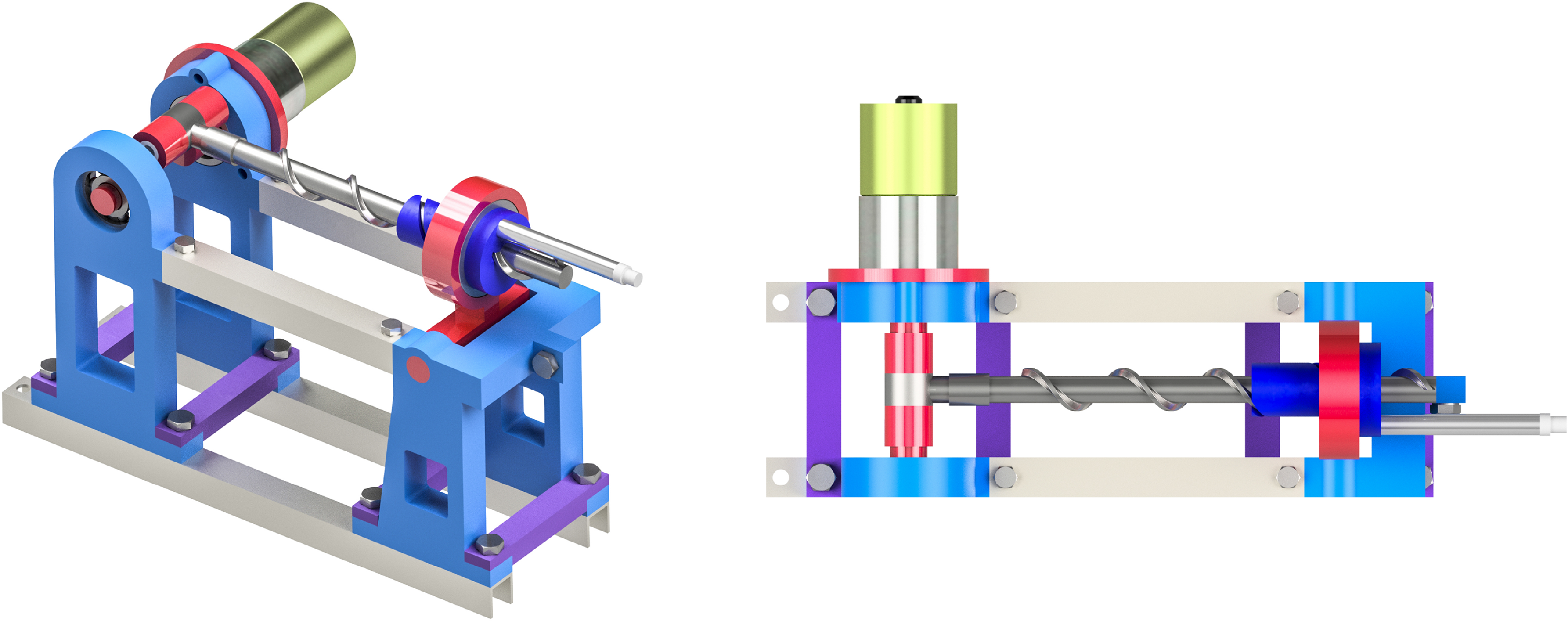
Numerical simulations of the developed 4R1H mechanism require specifying the values of its geometrical and inertial parameters. For this purpose, we have developed a CAD model (virtual prototype) of the mechanism using the Autodesk Inventor software (Figure 8). This model allows us to set the material of the links and accurately determine their lengths, locations of COMs, masses, and inertia matrices. The virtual prototype can also be used to perform kinematic and dynamic simulations in the CAD software and validate the proposed theoretical formulations. In addition, we can specify friction coefficients and carry out dynamic simulations with friction effects, which are challenging to consider in analytical computations. Subsection 7.2 will show that friction can significantly affect the computed motor torque.
Virtual prototype (CAD model) of the 4R1H mechanism.

In the prototype, the rotation axes of the crank and the rocker do not lie in the horizontal plane (Figure 8). This means the
 $Oy$
axis of base frame
 $Oxyz$
is not horizontal either. This axis is inclined relative to the horizontal line for angle
 $\alpha ={\textrm{atan2}}(l_5^z, l_5^y)$
, where
 $l_5^y$
and
 $l_5^z$
are the horizontal and vertical displacements of the rocker axis relative to the crank axis. Such a design affects the computation of forces
 $\mathbf{F}_i$
in Eq. (35), where we get:
 \begin{equation*} \mathbf {g} = g {\begin {bmatrix} 0 & -\sin\! (\alpha ) & -\cos\! (\alpha ) \end {bmatrix}}^{\mathrm {T}}, \end{equation*}
with
 $g = 9.81\text{ m/s$^2$}$
.
According to the CAD model, the mechanism has the following geometrical parameters:
 $p = 25\text{ mm}$
,
 $l_1 = 20\text{ mm}$
,
 $l_4 = 40\text{ mm}$
,
 $l_5^y = 160\text{ mm}$
,
 $l_5^z = -20\text{ mm}$
, and we compute
 $l_5 = ((l_5^y)^2 + (l_5^z)^2)^{1/2}$
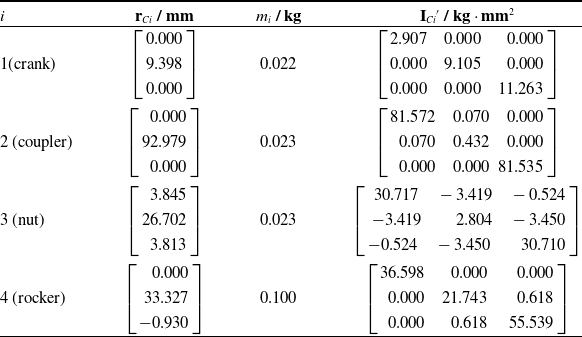
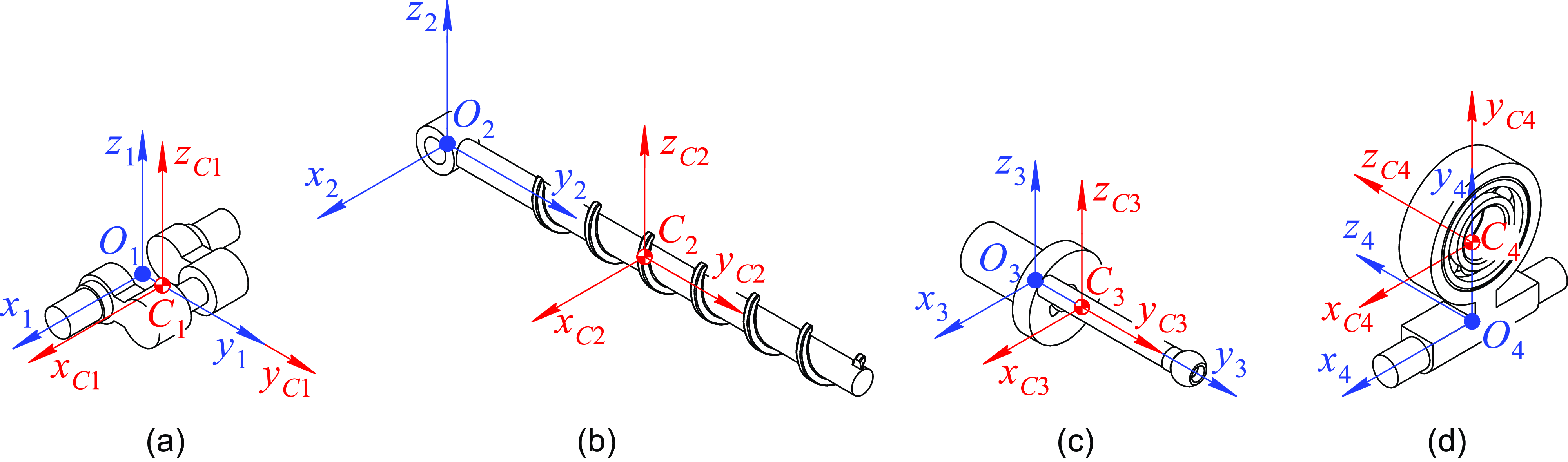
. Table I lists the inertial parameters of the links. Inertia matrices
 $\mathbf{I}_{Ci}'$
,
 $i = 1, \dots, 4$
, are computed with respect to the
 $C_ix_{Ci}y_{Ci}z_{Ci}$
reference frames located at the COMs according to Figure 9. Thus, we have determined all kinematic and dynamic parameters, which are necessary for numerical simulations.
Inertial parameters of the mechanism links.

Mechanism links and their reference frames: (a) crank; (b) coupler; (c) nut; (d) rocker. Blue frames correspond to Figure 7. Red frames have the same orientation as the blue ones, and they are located at the COMs of the links. The COMs are determined using the virtual prototype (Figure 8).

7.2. Numerical simulations
This subsection will look at two examples of the kinematic and dynamic analysis of the 4R1H mechanism. In the first example, we suppose the crank rotates at a constant speed and consider three different values of this speed:
 $5$
rpm,
 $10$
rpm, and
 $20$
rpm. To perform the kinematic and dynamic analysis, we have implemented the algorithms from Sections 5 and 6 in Julia.Footnote
3
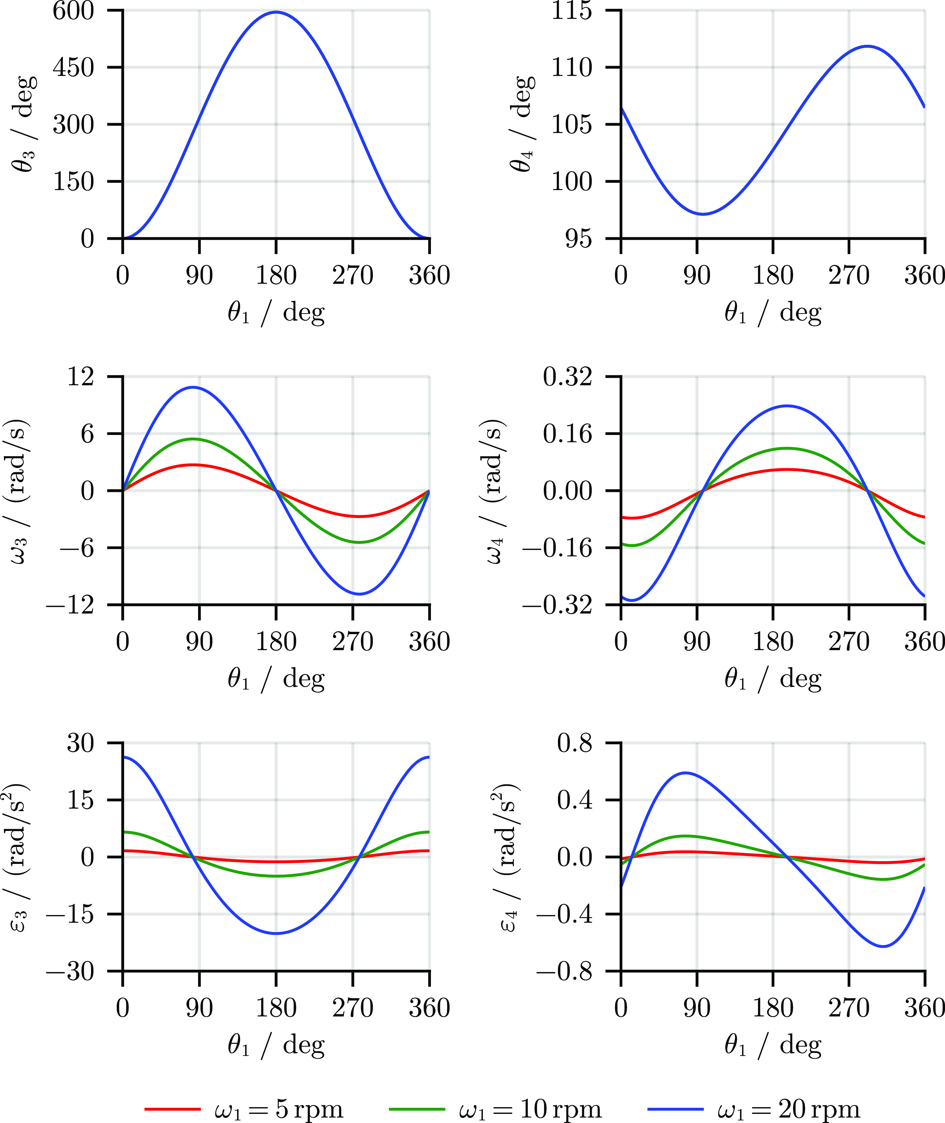
Figure 10 illustrates the results of the kinematic analysis for one revolution of the crank. As expected, the shape of the plots for angles
 $\theta _3$
and
 $\theta _4$
does not depend on crank speed
 $\omega _1$
: the plots coincide for all three considered values of the crank speed. The absolute values of angular speeds
 $\omega _3$
and
 $\omega _4$
increase linearly as the crank speed increases: this behavior matches Eqs. (14)–(16). On the other hand, the absolute values of angular accelerations
 $\varepsilon _3$
and
 $\varepsilon _4$
grow more rapidly because they are quadratic functions of crank speed
 $\omega _1$
, as we see from Eqs. (17)–(19). We have also performed similar simulations in Autodesk Inventor and got identical results, which we omit here for clarity.
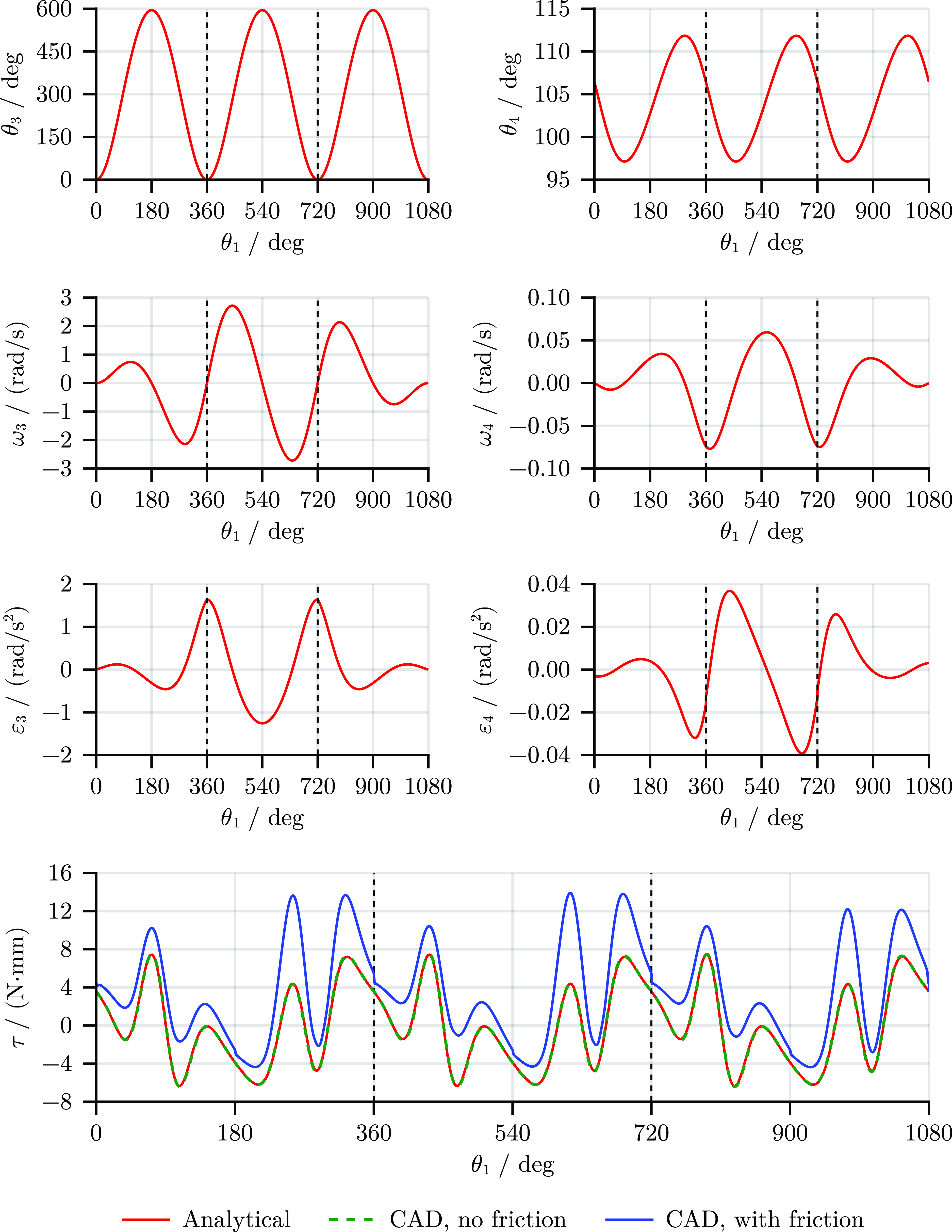
Results of the kinematic analysis for one revolution of the crank at various angular speeds.

The results show angle
 $\theta _3$
increases and reaches the highest value of about
 $600^\circ$
when the crank makes a half-turn. This agrees with the mobility analysis we did in Section 3: the output link changes the direction of its rotation about the screw axis when the crank becomes aligned with the base link. Angular speeds
 $\omega _3$
and
 $\omega _4$
vary smoothly—the mechanism does not meet the singular configuration discussed at the end of Section 4.
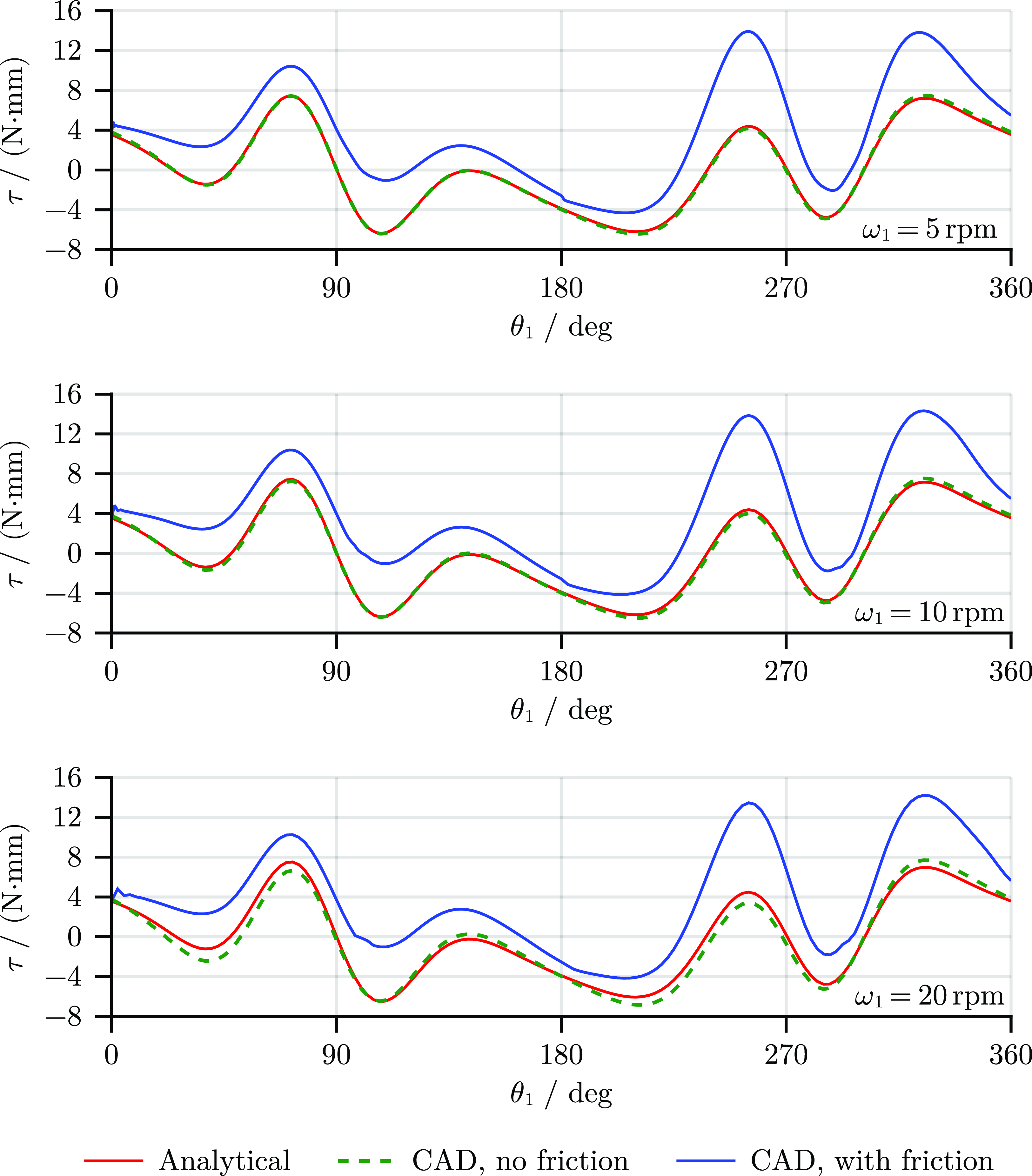
Comparison of the torque computation results between the analytical and CAD methods.

Computed motor torque for one revolution of the crank at various angular speeds.

Figure 11 shows the solution to the inverse dynamic problem computed with various methods for three different values of the crank speed. First, we applied the analytical method proposed in Section 6 (the red lines in Figure 11). Table II also presents maximum torque
 $\tau _{\text{max}}$
for each considered value of
 $\omega _1$
. The motor torque does not change much when the crank speed increases, and its highest value is about
 $7.5$
N
 $\cdot$
mm. Even if the crank speed increases four times, the torque increases by only
 $1$
%. These results indicate that the active forces (the weight of the links) dominate over the inertia forces, although the values of the latter should increase quadratically according to Figure 10 and the previous discussion. Next, we simulated the same motion in the Autodesk Inventor software using the developed virtual prototype (the green lines in Figure 11). Table II lists maximum torque
 $\tau _{\text{max}}^{\text{CAD}}$
, maximum torque deviation
 $\Delta _{\text{max}}$
between the two methods along the whole rotation, and the root-mean-square deviation for each value of
 $\omega _1$
. We see the torque deviations between the analytical and CAD methods increase with the increase in the crank speed. This behavior can be explained as follows. Kane’s method, implemented in the analytical approach, allows computing the motor torque without the need to determine the joint reactions. On the other hand, dynamic simulations in the CAD software always determine the motor torque together with these reactions. Since the considered 4R1H mechanism is overconstrained, there is an infinite number of solutions to the inverse dynamic problem. The CAD software finds the unique solution numerically, for example, using the minimum norm least squares method [Reference Callejo, Gholami, Enzenhöfer and Kövecses39], and the computed torque will differ from the real one. Thus, the torque calculations performed by the analytical method are more accurate.
Finally, we performed CAD simulations considering friction effects. We adopted a simple Coulomb model [Reference Farhat, Mata, Page and Díaz-Rodríguez40] with the following friction coefficients:
 $0.002$
for the bearings (in the base–crank and rocker–nut couplings) and
 $0.460$
for the joints without bearings (in other couplings). For the latter, we considered a plastic–plastic contact with no lubrication. The blue lines in Figure 11 show the peak torque is about
 $14$
N
 $\cdot$
mm for each considered value of
 $\omega _1$
, which is
 $87$
% higher than in the frictionless simulations. We can also observe a slight discontinuity in the computed torque when
 $\theta _1 = 180^\circ$
. In this configuration, the output link changes its direction of rotation about the screw axis (Figure 10), and friction forces in the H pair change their direction as well. Thus, the simulations show the friction effects can significantly affect the results. At the same time, there exists the same problem of solving the inverse dynamic problem for the overconstrained mechanism, as we considered in the previous paragraph, so the obtained results should be treated with caution. In Section 8, we will also discuss why it is difficult to consider friction within the analytical dynamic model.
In the second example, we add acceleration and deceleration phases to the crank rotation and consider three revolutions of the crank. During the first revolution, crank angular speed
 $\omega _1$
increases linearly from
 $0$
to
 $5$
rpm. For the second turn, the crank rotates at a constant speed. In the third and final revolution, the crank angular speed decreases linearly to zero.
Results of the kinematic and dynamic analysis for three revolutions of the crank with acceleration and deceleration phases and a middle phase with constant angular speed
 $\omega _1 = 5$
rpm. The dashed lines separate acceleration, constant speed, and deceleration phases of the motion. Results of the kinematic analysis coincide for the analytical and CAD computations, and the latter are omitted for clarity.

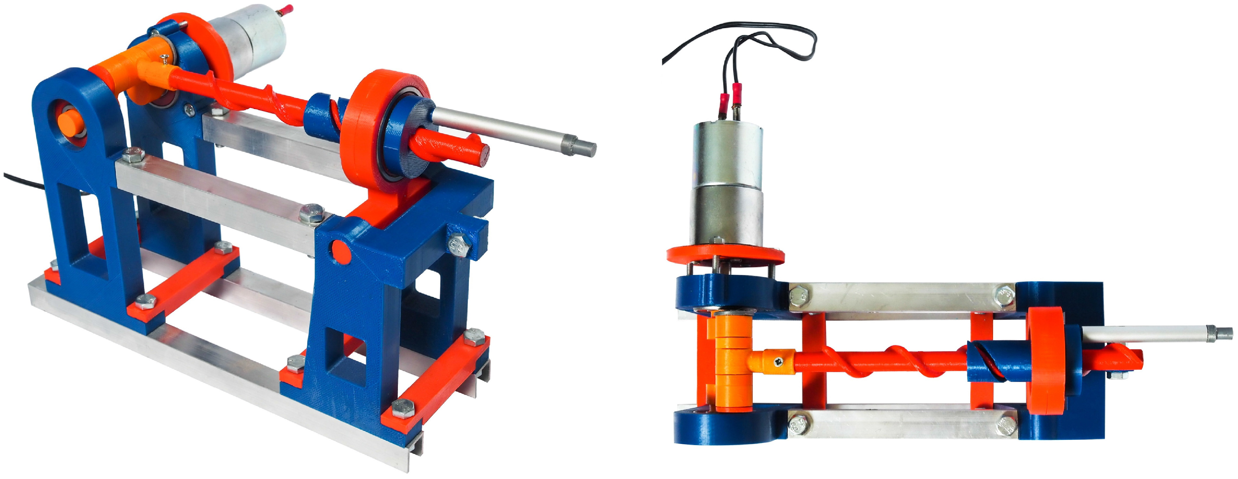
The actuated full-scale physical prototype of the 4R1H mechanism.

Figure 12 shows the results of the kinematic and dynamic analysis. The plots for angles
 $\theta _3$
and
 $\theta _4$
have three identical portions, which coincide with Figure 10. The amplitudes of angular speeds
 $\omega _3$
and
 $\omega _4$
and angular accelerations
 $\varepsilon _3$
and
 $\varepsilon _4$
increase during the acceleration phase, than they have the same shape as in Figure 10. After that, these amplitudes decrease as the crank decelerates. Unlike the first example, angular speed
 $\omega _4$
starts and finishes with a zero value because of the added transient modes. On the other hand, angular acceleration
 $\varepsilon _4$
still starts and finishes with a nonzero value and also has a slight discontinuity after the second and third revolutions of the crank. This is caused by the discontinuity of crank angular acceleration
 $\varepsilon _1$
. In practice, this behavior can be undesirable, and one can consider more complex transient regimes (e.g., using high-order polynomials or trigonometric functions [Reference Biagiotti and Melchiorri41]) to avoid any acceleration discontinuities.
Figure 12 also indicates that the motor torque behaves similarly in each of the three motion phases, and the shape of the torque curves match Figure 11. This result agrees with the first example where we found that the inertia effects did not contribute much to the motor torque. Finally, numerical simulations in Autodesk Inventor verify the analytical computations in both the kinematic and dynamic analysis. The small torque deviations between the CAD and analytical results are caused by the same reasons, as we discussed in the first example.Footnote 4
7.3. Physical prototyping
Using the CAD model, we have designed a physical prototype of the mechanism (Figure 13). The thin rod attached to the nut serves for visualization purposes and helps distinguishing the nut rotations. Dimensions of the links correspond to Subsection 7.1. Most prototype components are 3D-printed plastic parts made of polylactic acid (PLA). Other components represent easy-to-access standard elements, including aluminum profiles, ball bearings (in the base–crank and rocker–nut couplings), and fasteners.
We have designed the prototype mainly for illustrative purposes: it is supposed to operate at a crank speed of
 $5$
rpm without any payload. Based on the numerical simulations discussed in the previous subsection, we have selected a
 $12$
V ”Zheng“ ZGA37RG DC motor with a
 $1\,:\,627$
gearbox to actuate the mechanism. The output rated speed and rated torque of the motor are
 $5$
rpm and
 $1$
N
 $\cdot$
m, respectively, which matches the desired motion.
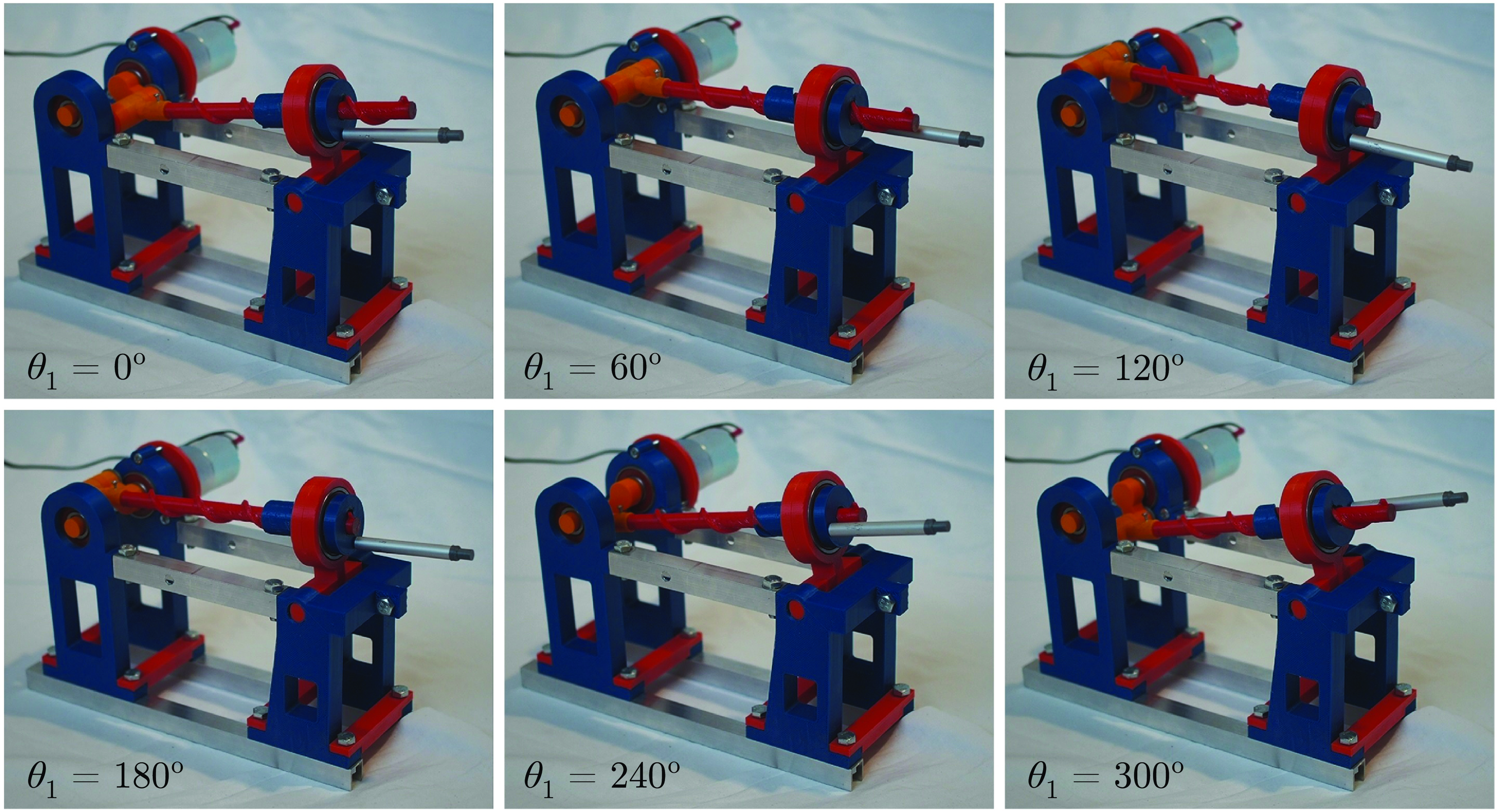
Figure 14 shows the physical prototype during operation for one revolution of the crank performed at a crank speed of
 $5$
rpm. The observed motion corresponds to the kinematic simulations. The mechanism does not meet any singularities during the motion cycle and has no jamming in the helical pair, which verifies its performance ability.
The physical prototype during operation for one revolution of the crank.

8. Discussion
This paper focused on the synthesis and analysis of single-loop 1-DOF lever-screw mechanisms with a 4R1H structure. These mechanisms can become the basis for developing other single- and multi-loop mechanical systems with multiple DOFs like the ones presented in studies [Reference Chen, Wang, Wang, Chen, Parenti-Castelli and Angeles42] and [Reference Li, Fang and Wang43]. We should mention one subtlety of designing such mechanisms. During the type synthesis, we combined an HR monad with an RRR dyad along the common translational motion. However, if we combine this or RH monad and any planar dyad along the common rotational motion (Figure 2b), we will not derive a spatial mechanism. The freedom in the H pair will remain inactive, and any mechanism synthesized this way will behave like a planar four-bar linkage. A similar situation appears when we couple any planar dyad with an HP (PH) dyad along the common translation. In paper [Reference Fomin and Antonov21], we elaborated on this issue and considered other possible combinations of screw monads and planar dyads.
The performed mobility and kinematic analysis employs similar approaches and presents similar results as we got for another 4R1H mechanism in paper [Reference Fomin, Antonov, Glazunov, Filippov and Okada22]. Likewise, we can use the developed techniques to analyze any other 4R1H mechanism synthesized in Section 2. The presented method of dynamic analysis is also suitable for any mechanism of this class. Indeed, the only differences will be in the kinematic parameters we compute in Subsection 6.2. Dynamic Eqs. (20)–(23), (34), and (35) remain valid for all the mechanisms. This motivates the formulation of dynamic equations in a general form. Of course, for the links that perform planar motion, we could consider computations with scalar and constant inertia moments instead of
 $3 \times 3$
variable inertia matrices. In this case, however, it would be more difficult to adapt the presented techniques to other 4R1H mechanisms.
During the dynamic analysis, we ignored friction effects. Although the considered 1-DOF mecha- nism has only five joints, modeling these effects correctly can be quite complicated, as shown in paper [Reference Harlecki and Urbaś44]. Even if we apply a typical Coulomb model of friction forces [Reference Farhat, Mata, Page and Díaz-Rodríguez40], this will require us to determine joint reactions. The considered 4R1H mechanisms are overconstrained, and solving this problem becomes problematic. Indeed, each mechanism has five 1-DOF joints, so there are
 $5 \times 5 = 25$
joint reactions to be found (apart from the motor torque, which we can compute using the proposed method). On the other hand, we can compose only
 $4 \times 6 = 24$
dynamic (Newton–Euler) equations. If we look at the planar motion of the mechanism, there are
 $12$
unknown joint reactions:
 $6$
reactions from three R joints, whose axes are orthogonal to the motion plane, and
 $6$
reactions from the remaining R and H joints, whose axes are parallel to this plane. Thus, we can compute these reactions from
 $4 \times 3 = 12$
dynamic equations of planar motion. We are left with
 $13$
joint reactions to be determined from the
 $12$
remaining equations—this problem has an infinite number of solutions in a general case. Furthermore, the statements above are valid if we compute the motor torque in advance using the proposed approach. This approach, however, ignored friction forces, so we have returned to the starting point of our discussion. The performed analysis verifies the complexity of considering friction effects within the dynamic analysis. Subsection 7.2 shows the CAD software can deal with this issue, but the obtained results should be treated with caution, including the frictionless case. Studies [Reference Liu, Xu, Yao and Zhao45, Reference Wojtyra, Pȩkal and Fraczek46] present various techniques to tackle this problem, which is beyond the current paper but can be the subject of future investigations.
9. Conclusion
The paper has considered the synthesis, analysis, and prototyping of 1-DOF five-bar single-loop lever-screw mechanisms. Among the large variety of these mechanisms, we have focused on a class of 4R1H mechanisms. Most links of these mechanisms move in parallel planes, while the output link can perform spatial motion and reproduce screw-like trajectories around curvilinear axes.
The main achievements and contributions of the performed study are the following:
-
• We started with the type synthesis of the 4R1H mechanisms and proposed the approach for generating novel mechanisms. The synthesis involves combining two kinematic chains with planar and cylindrical motion types along the common translation. By using the helical joint in the cylindrical chain, we generate a family of novel 1-DOF spatial mechanisms. The rest of the paper focused on one 4R1H mechanism as a representative example.
-
• After that, we applied screw theory to verify that the mobility of the mechanism is full-cycle and considered its singular configurations. By analyzing the minors of the twist matrix, we derived the geometrical conditions when the mechanism gains uncontrollable freedoms. The paper discussed how to avoid these singularities and presented the design of a singularity-free mechanism.
-
• Next, we performed the kinematic and dynamic analysis of the considered 4R1H mechanism. The dynamic model, based on Kane’s equations, considers the weight and inertia of all the links. The obtained analytical relations allow expressing the kinematic parameters of the links as a function of input motion and computing the motor torque required for this motion.
-
• The subsequent numerical examples simulated in Julia illustrated the application of the developed kinematic and dynamic algorithms. We considered three different angular speeds of the crank:
$5$
rpm,
$10$
rpm, and
$20$
rpm. The simulations show that even when the crank angular speed increases four times, the motor torque increases by only
$1$
%. These results indicate that the weight of the links dominates over inertia forces. -
• In addition, we simulated the case when the crank speed increased linearly during the first turn, kept a constant value of
$5$
rpm for the second turn, and then decreased linearly back to zero. The results show these transient regimes do not affect the motor torque, which agrees with the constant speed examples. -
• To verify the results, we performed similar examples in Autodesk Inventor and solved the inverse dynamic problem for two cases: with and without friction. The CAD simulations show the motor torque increases by
$87$
% when we consider the friction effects. One should handle these results with care because of the method the CAD software uses to analyze the dynamics of overconstrained mechanisms. -
• Finally, we used the simulation results to select a DC motor with a
$1\,:\,627$
gearbox and design a physical prototype of the mechanism. Most components of the prototype are 3D-printed plastic parts and standard elements. The experiments show the mechanism works well without jamming and meeting singular configurations.


The performed research has laid the foundations for the analysis and design of 4R1H mechanisms. The developed techniques can be adapted to other lever-screw and five-bar mechanisms. Future studies will include a dimensional synthesis of such mechanisms, developing more elaborate dynamic models that consider friction effects, and designing other mechanisms with multiple DOFs based on the presented ones.
Author contributions
AF and AA conceived and designed the study. AF and VG devised the type synthesis method. AA performed mobility analysis and kinematic and dynamic simulations in Julia. AF designed virtual and physical prototypes and made simulations in Autodesk Inventor. AF and AA prepared graphical material and wrote the manuscript. AF, AA, and VG supervised the article.
Financial support
This research was supported by Russian Science Foundation (RSF) under grant No. 21-79-10409, https://rscf.ru/en/project/21-79-10409/.
Conflicts of interest
The authors declare no conflicts of interest exist.
Data availability statement
Julia programs, results of dynamic simulations performed in Autodesk Inventor, and a movie of the physical prototype operation are available free online at https://dx.doi.org/10.17632/3ncbhdd4nw.4.
Ethical approval
Not applicable.