1. Introduction
Industrial robots are now widely used in assembling certain simple geometric parts (such as the cross section is circular or rectangular parts). However, for parts composed of these cross sections (such as parallel keys and rectangle splines) and irregular cross-sectional parts, assembly problems have not been carried out in-depth. Therefore, in order to promote the application of automatic assembly technology of complex peg and hole parts by industrial robot, this paper creatively carried out the research on the robot assembly theory of circular-rectangular compound peg and hole parts, which provides important theoretical guidance and practical application value for the further development of robot assembly.
For the assembly of cylindrical peg and hole parts, Simunovi [Reference Simunovi1] was the first to put forward the practical problem of cylindrical part robot assembly. The contact states of the cylindrical part in two dimensions was deduced when it is inserted, and the jamming diagram was drawn from it. Whitney [Reference Whitney2] combined with Simunovic’s analysis, summed up the two mechanical states of jamming and wedging in parts assembly, and derived the geometric conditions to satisfy assembly. Meanwhile, Remote Compliance Center (RCC) was designed. Usubamatov and Leong [Reference Usubamatov and Leong3] deduced the boundary conditions of jamming and established the relationship between the insertion depth and the inclination angle of peg and hole. For the assembly of square peg and hole parts, Caine et al. [Reference Caine, Lozano-Perez and Seering4] analyzed assembly process of square parts without chamfering and summed up four contact states during assembly. In 2012, Park et al. [Reference Park, Park, Do, Choi and Kyung5] planned the assembly process of square peg and hole into six stages, analyzed the contact situation of each stage, and formulated the assembly strategy to achieve the assembly task. Kim et al. [Reference Kim, Kim, Seo, Kim and Kim6] designed a dexterous hand with an angle measuring system to achieve the assembly of square peg and hole. Five possible contact states are obtained by analyzing the contact states of peg and hole. For the assembly of circular-circular compound peg-in-hole, Ohwovoriole [Reference Ohwovoriole7] extended the screw theory to analyze the assembly problem of multiple cylindrical peg and hole parts and decomposed the assembly problem into multiple single cylindrical peg and hole. Sathirakul and Sturges [Reference Sathirakul and Sturges8] divided the assembly problem of two cylindrical peg and hole parts into 4 parts in two dimensions and listed 26 possible contact states, deduced the force/moment conditions, and obtained the two dimensions jamming diagram. Fei and Zhao [Reference Fei and Zhao9] broadened the analysis of contact state in two dimensions, analyzed the force of contact state of two cylindrical peg in three dimensions, and drew the jamming diagram accordingly. Zhang et al. [Reference Zhang, Xu, Chen, Zhao and Chen10] analyzed the assembly problem of dual flexible cylindrical peg and hole parts and proposed an assembly method of flexible dual peg and hole parts. Zhou et al. [Reference Zhou, Liu and Chen11] verified the correctness of the assembly theory of two cylindrical peg and holes according to the actual assembly of alternator frame.
In order to realize the robot assembly task of peg and hole, the first problem to be solved is the hole searching problem. In terms of the hole searching method, Newman et al. [Reference Newman, Zhao and Pao12] proposed to train the neural network by recording the contact force of each contact point of the peg in the searching space and establish the mapping relationship between the force/moment and the relative position of the peg and hole during the search. Through the method of pretrained neural network, the searching speed can be improved, which is a plane searching method. Sharma et al. [Reference Sharma, Shirwalkar and Pal13] considered the inclination angle between pegs and holes according to the hole searching strategy proposed by Newman. However, if the inclination angle between the peg and holes changes, the neural network needs to be retrained, so the application of this method is also limited. In addition, Sharma et al. [Reference Sharma, Shirwalkar and Pal14] converts the hole searching problem into the problem of finding the minimum depth contour value for a specific assembly and guides the robot positioning with convex optimization method to complete the hole searching task. In addition, there is also a hole searching method of visual. Huang et al. [Reference Huang, Zhang, Chen and Ota15] applied Baxter dual-arm robot and installed a camera at each end of both arms to achieve the assembly of circular pegs and holes with a gap of 0.1 mm. Kim et al. [Reference Kim, Song and Song16] proposed a shape recognition algorithm and a detection algorithm of peg and hole based on six-dimensional force sensor, regardless of the size of the error between hole and hole, and this algorithm can accurately detect the hole and applies not only to assembly of circular peg and hole but can also be applied to assembly of square peg and hole, and he also developed a blind searching algorithm which can be easily applied to the assembly of square pegs and holes, The success rate of the assembly experiment of square pegs and holes is 93%.
In terms of control strategy for part assembly, In 2008, Yun [Reference Yun17] proposed a passive flexible joint using gradient descent algorithm to solve assembly of peg and hole. In 2014, Park et al. [Reference Park, Kim, Bae, Park, Baeg and Park18] improved Yun’s flexible device by replacing the RCC with a programable flexible device, including programable springs and dampers. This improvement solves some problems in dual-arm cooperative assembly of peg and hole, which related to limited resolution or accuracy in detecting interference or gaps in an unstructured environment. These passive flexible control methods have the characteristics of high response speed, low cost, and reliability. However, passive flexible devices also have great defects, such as limited compensation for errors, and only suitable for assembly of simple parts. Therefore, in order to overcome the above defects, Tsumugiwa et al. [Reference Tsumugiwa, Sakamoto, Yokogawa and Hara19] proposed a controller that changed the control mode according to the task mode and adopted the position-based impedance control strategy and the torque control strategy that compensated the dead weight and friction to achieve human–machine cooperative handling tasks and assembly tasks. Mol et al. [Reference Mol, Smisek, Babuška and Schiele20] proposed a closed-loop nested admittance/impedance control strategy based on force sensors to proactively estimate and minimize the effects of naturally occurring geometric misalignment when using robots for assembly tasks. In addition, some intelligent control methods have also been proposed. Fan et al. [Reference Fan, Xu, Ho and Leung21] proposed an adaptive fuzzy genetic learning algorithm for updating controller parameters, controlling actuator positions and contact forces to improve control accuracy and robustness of the control system. Wang [Reference Wang22] proposed a force-position hybrid control strategy to realize the interaction between position control and force control and developed an assembly control technology of peg and hole combining visual and force feedback, which achieved the expected joint flexibility by combining the fuzzy sliding mode joint impedance controller and could deal with model uncertainties and external disturbances. Jasim et al. [Reference Jasim, Plapper and Voos23] proposed a model-free robust adaptive control strategy, which relied on adaptive fuzzy system, sliding mode control, and universal Lyapunov function, and ensured the global stability of the system under the condition that all closed-loop signals were bounded and realized the assembly of flexible rubber parts. This intelligent control method does not need to analyze the contact state of assembly, but the training has high cost and low universality, so it can only deal with the assembly of one part in general.
The current visual assembly system is mostly used for the positioning of parts. Due to the lack of corresponding force feedback mechanism, jamming or wedging can easily occur during the assembly process, which leads to the damage of parts. Moreover, it is difficult to ensure the accuracy under the circumstance of limited light source environment, and the training cost is also greatly increased. The impedance control method is not limited by the environment and the geometry of the parts and can effectively avoid the jamming and wedging according to the feedback of the contact force. Meanwhile, the contact between the end of the manipulator and the environment is equivalent to the spring damping model, which greatly improves the flexibility of the contact and plays a certain role in protecting the parts.
Aiming at the assembly of circular-rectangular compound peg and hole parts, one corresponding contact model is set up in this paper. The contact state is judged by the information collected by the six-dimensional force/torque sensor, so as to adjust the corresponding pose. The method of combining impedance control and position control is adopted, and by analyzing the dynamic relationship between the end of the robot arm and the environment, the force control and position control are considered together, which can realize the precise control of position and ensure a certain flexibility and high reliability.
It can be seen that at present, the robot assembly theory is often focused on some parts with simple geometry, while the research on the assembly of parts with complex shape has not been carried out. The assembly object studied in this paper, circular-rectangular compound peg and hole parts, is a kind of complex parts. Therefore, it is necessary to discuss the assembly theory of this type complex parts. In order to solve the assembly problem of circular-rectangular compound peg and hole parts, this paper takes one of these parts as the analysis object, uses the quasi-static equilibrium, combined with geometric features to establish the mathematical model of parts and environment contact, and uses the feedback information of six-dimensional force sensor to calculate the contact state to guide assembly. This type of analysis also enables the analysis of assembly problems of other types of complex parts.
The remainder of this study is organized as follows: in Section 2, the contact states of complex parts in assembly are analyzed and summarized, and the force conditions of maintaining each contact state are calculated; Section 3 analyzes the jamming during assembly and obtains the conditions to avoid jamming; in Section 4, the assembly strategy is given, including hole searching strategy, contact state recognition strategy, and pose adjustment strategy. In Section 5, the simulation verification is given, including jamming simulation and assembly simulation. In Section 6, the future work is summarized.
2. Contact states classification and force analysis
2.1. Problem description
The circular-rectangular compound peg and hole parts are with circular and rectangular cross-sectional features. The typical cross-sectional geometric features are shown in Fig. 1. In this paper, the parts with such cross-sectional features are collectively referred to circular-rectangular compound peg and hole parts.
Geometric characteristics of peg and hole section of circular-rectangular compound peg and hole parts.

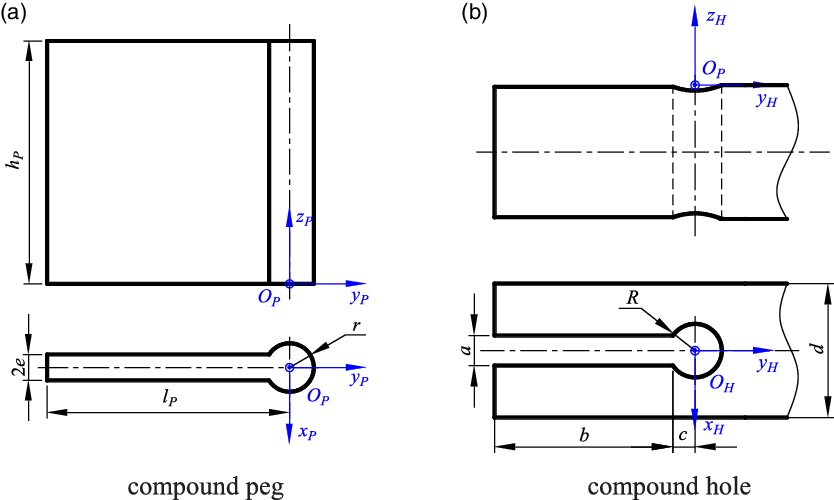
In this paper, the part which cross section composed of one circle and one rectangular is selected as an example, as shown in Fig. 2. The radius of the cylindrical part of the peg and the hole are
 $r$
and
 $R$
, the width of the rectangular column part of the hole is
 $a$
, the length is
 $b$
, the distance between the edge of the rectangular column part of the hole part and the center of the cylinder part is
 $c$
, and the half width of the rectangular column part of the peg is
 $e$
. The height of the peg is
 $h_{p}$
. The distance from the edge of the rectangular column to the center of the cylinder is
 $L_{p}$
. The peg coordinate system
 $O_{P}x_{P}y_{P}z_{P}$
is selected at the center of the bottom surface of cylindrical part of peg, and the hole coordinate system
 $O_{H}x_{H}y_{H}z_{H}$
is selected at the center of the upper end face of the circular hole. In the following, the analysis is carried out in the coordinate system
 $O_{P}x_{P}y_{P}z_{P}$
.
Geometric dimension parameters and corresponding coordinate system of parts.

The geometry of parts studied in this paper satisfies the following conditions:
-
a. The radius of the cylindrical peg should be less than the radius of the cylindrical hole, and the width of the rectangular peg should be less than the rectangular hole, that is:
(1) \begin{equation}r\lt R\text{ and }2e\lt a\end{equation}
-
b. The cylindrical part intersects with the rectangular part, namely:
(2)
\begin{equation}c\lt R\end{equation}
-
c. The diameter of cylindrical part should be greater than the width of the rectangular part, namely:
(3)
\begin{equation}r\gt e\text{ and }2R\gt a\end{equation}


In order to analyze the force of circular-rectangular compound peg and hole parts during assembly, the following assumptions are made for the model:
-
1. The speed of the peg relative to the hole is very small, and the collision between parts is not considered in the assembly process. Assembly process can be regarded as quasi-static process.
-
2. In the insertion stage after the hole searching stage has been completed, the angular error between the peg and the hole is so small that it can be ignored.
-
3. The parts are regarded as rigid bodies, that is, the influence of deformation on the force is not considered when the peg and hole contacts.
-
4. The whole assembly process is vertically downward along the axis of the peg.
-
5. During the assembly process, the frictional force along the z-axis direction of the peg coordinate system is not considered.
2.2. Contact states of circular-rectangular compound peg and hole parts
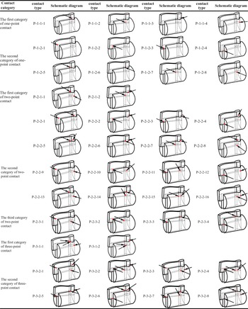
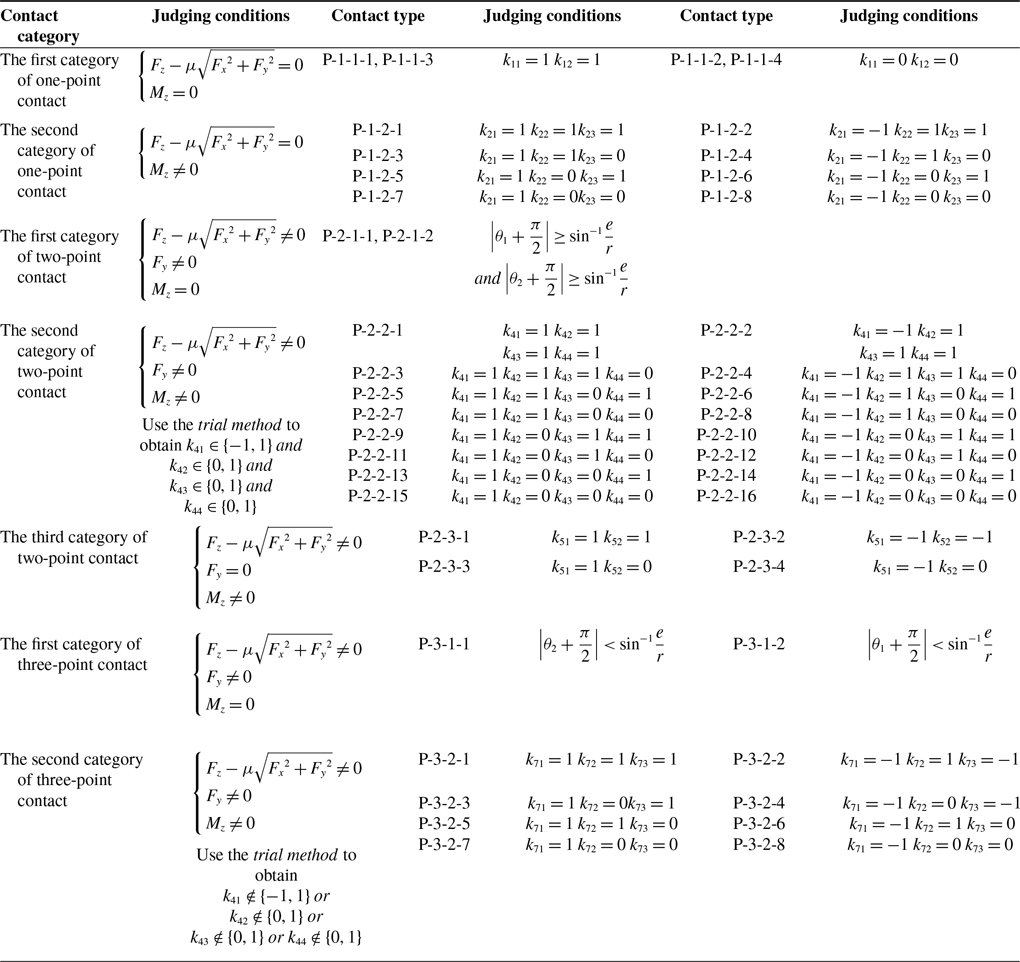
In the assembly process, the ideal state is that the hole and the peg are perfectly aligned, and the peg does not come into contact with the hole during insertion, and the assembly can be completed without interruption. In the actual assembly, however, there will inevitably be deflection angle between peg and hole, and because of the complex shape of circular-rectangular compound peg and hole parts, it is inevitable to produce a variety of contact states in assembly. For ease of further analysis, this section classifies the contact states according to the number and location of contact points, and 7 categories of 44 contact states are obtained, as shown in Table I. In order to express each contact state accurately, the symbols used are as follows:
 \begin{equation*} P-u-v-w \end{equation*}
where
 $P$
means the point contact,
 $u$
is the number of contact points,
 $v$
is the parameter determined by the position of contact points, represents the contact category, and
 $w$
represents the contact type under a certain category. For example, the number P-1-2-3 represents the third contact state under the second contact category under one-point contact.
Contact state classification.

2.3. Analyzing contact force/moment of circular-rectangular compound peg and hole parts
After analyzing the contact state, we can plan the assembly strategy. However, to guarantee the assembly’s success, it is necessary to analyze the force/moment generated in assembly to ensure the insertion force
 $\left[F_{x}\ \ F_{y}\ \ F_{z}\ \ M_{x}\ \ M_{y }\ \ M_{z}\right]^{T}$
satisfies certain conditions. In this section, taking one-point contact state P-1-1-1, P-1-2-1 and two-point contact state P-2-2-1 as examples, the force/moment conditions for maintaining each contact state are derived, and other contact states can be analyzed similarly.
-
1. One-point contact state P-1-1-1
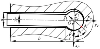
For the contact state P-1-1-1, the contact point is located in the cylindrical part of the composite, as shown in Fig. 3, and the contact point position is
 $\boldsymbol{{r}}_{c1}=\left[r{\cos} \theta _{1}\ \ r{\sin} \theta _{1}\ \ h\right]^{T}$
, assuming that the force at the contact point is
 $f_{c1}$
. According to the quasi-static equilibrium equation, there are
Schematic diagram of contact state P1-1-1.

 \begin{equation}\left[\begin{array}{c} \boldsymbol{{F}}\\[4pt] \boldsymbol{{M}} \end{array}\right]=\left[\begin{array}{c} -f_{c1}{\cos}\theta _{1}\\[4pt] -f_{c1}{\sin} \theta _{1}\\[4pt] \mu f_{c1}\\[4pt] f_{c1}h{\sin} \theta _{1}+\mu f_{c1}r{\sin} \theta _{1}\\[4pt] -f_{c1}h{\cos} \theta _{1}-\mu f_{c1}r{\cos} \theta _{1}\\[4pt] 0 \end{array}\right]\end{equation}
where
 $\boldsymbol{{F}}$
and
 $\boldsymbol{{M}}$
are expressed in
 $O_{P}x_{P}y_{P}z_{P}$
. The force and moment information are obtained from the six-dimensional force sensor through coordinate transformation, where
 $\boldsymbol{{F}}=\left[F_{x}\ \ F_{y}\ \ F_{z} \right]^{T}$
,
 $\boldsymbol{{M}}=\left[M_{x}\ \ M_{y }\ \ M_{z} \right]^{T}$
. Use
 $s_{i}, c_{i}$
denote
 ${\sin} \theta _{i}$
and
 ${\cos} \theta _{i}(i=1,2,3,4)$
, respectively.
 $\theta _{i}$
is the azimuth of the contact point in the
 $x-y$
plane of
 $O_{P}x_{P}y_{P}z_{P}$
.
 $i=1,2,3,4$
represents the first category of one-point contact 1 (Namely p1-1-1), the first category of one-point contact 2 (Namely p1-1-2), the first category of one-point contact 3 (Namely p1-1-3), and the first category of one-point contact 4 (Namely p1-1-4), respectively. Thus, according to formula (4), the force/moment relationship of contact state P-1-1-1 can be obtained as follows:
 \begin{align}\begin{cases} \dfrac{F_{x}}{F_{z}}=-\dfrac{c_{1}}{\mu }\\[11pt] \dfrac{M_{y}}{F_{z}}=-\dfrac{\left(h+\mu r\right)\!c_{1}}{\mu } \end{cases}\end{align}
 \begin{align}\begin{cases} \dfrac{F_{y}}{F_{z}}=-\dfrac{s_{1}}{\mu }\\[11pt] \dfrac{M_{x}}{F_{z}}=\dfrac{\left(h+\mu r\right)\!s_{1}}{\mu } \end{cases}\end{align}
-
2. One-point contact state P-1-2-1
For one-point contact state P-1-2-1, the position of the contact point is located in the rectangle column part, and the position of the contact point is
 $\boldsymbol{{r}}_{r1}=\left[-e-\!\left(b+c\right) h\right]^{T}$
. Similarly, according to the quasi-static equilibrium equation:
 \begin{equation}\left[\begin{array}{c} \boldsymbol{{F}}\\[5pt] \boldsymbol{{M}} \end{array}\right]=\left[\begin{array}{c} f_{r1}\\[5pt] 0\\[5pt] \mu f_{r1}\\[5pt] -\mu f_{r1}\!\left(b+c\right)\\[5pt] f_{r1}h+\mu f_{r1}e\\[5pt] f_{r1}\!\left(b+c\right) \end{array}\right]\end{equation}
where
 $f_{r1}$
is the normal contact force on the peg at the contact point
 $R_{1}$
when it is in one-point contact. According to the above formula, it can be concluded that:
 \begin{align}\begin{cases} \dfrac{F_{x}}{F_{z}}=\dfrac{1}{\mu }\\[11pt] \dfrac{M_{y}}{F_{z}}=\dfrac{h+\mu e}{\mu } \end{cases}\end{align}
 \begin{align}\begin{cases} \dfrac{F_{y}}{F_{z}}=0\\[11pt] \dfrac{M_{x}}{F_{z}}=-\!\left(b+c\right) \end{cases}\end{align}
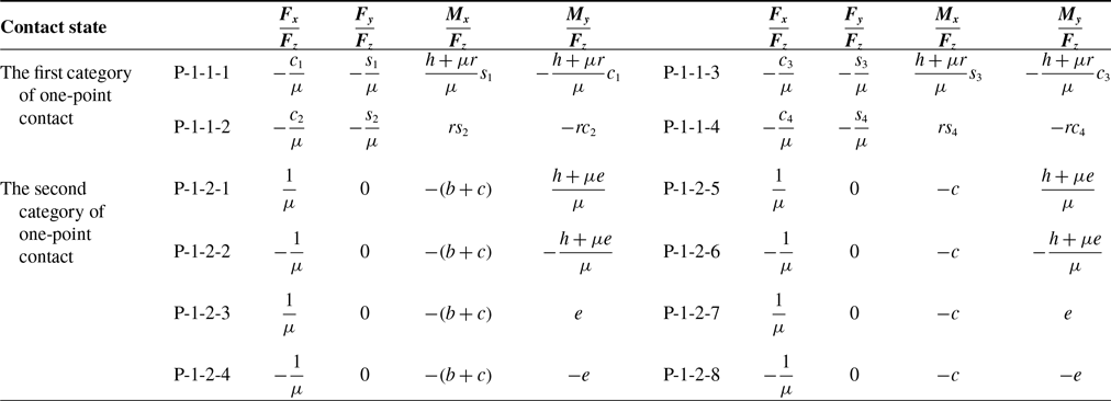
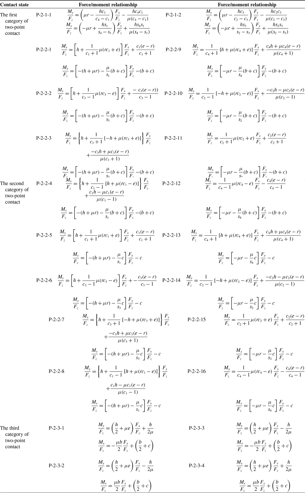
The force analysis of other contact states is similar to the above analysis, and the results are shown in Table II.
Force/moment relationship in one-point contact.

-
3. Two-point contact state P-2-2-1
For two-point contact state P-2-2-1, it is composed of one-point contact state P-1-1-1 and contact state P-1-2-1. From the combination and decomposition of forces, the force state of P-2-2-1 can be obtained from Eqs. (4) and (7), namely:
 \begin{equation}\left[\begin{array}{c} \boldsymbol{{F}}\\[5pt] \boldsymbol{{M}} \end{array}\right]=\left[\begin{array}{c} -f_{c1}c_{1}+f_{r1}\\[5pt] -f_{c1}s_{1}\\[5pt] \mu f_{c1}+\mu f_{r1}\\[5pt] f_{c1}hs_{1}+\mu f_{c1}rs_{1}-\mu f_{r1}\!\left(b+c\right)\\[5pt] -f_{c1}hc_{1}-\mu f_{c1}rc_{1}+f_{r1}h+\mu f_{r1}e\\[5pt] f_{r1}\!\left(b+c\right) \end{array}\right]\end{equation}
According to the above formula, it can be concluded that:
 \begin{equation}\dfrac{M_{y}}{F_{z}}=\left[h+\dfrac{1}{c_{1}+1}\mu \!\left(rc_{1}+e\right)\right]\dfrac{F_{x}}{F_{z}}+\dfrac{c_{1}\!\left(e-r\right)}{c_{1}+1}\end{equation}
 \begin{equation}\dfrac{M_{x}}{F_{z}}=\left[-\!\left(h+\mu r\right)-\dfrac{\mu }{s_{1}}\!\left(b+c\right)\right]\dfrac{F_{y}}{F_{z}}-\!\left(b+c\right)\end{equation}
Formula (11) and (12) shows a certain linear relationship. For formula (11), if
 $\dfrac{F_{x}}{F_{z}}=-\dfrac{c_{1}}{\mu }$
, The equation is simplified as (5), namely:
 $\dfrac{M_{y}}{F_{z}}=-\dfrac{hc_{1}+\mu rc_{1}}{\mu }$
. If
 $\dfrac{F_{x}}{F_{z}}=\dfrac{1}{\mu }$
, Then formula (8) is obtained, that is
 $\dfrac{M_{y}}{F_{z}}=\dfrac{h+\mu e}{\mu }$
. For formula (12), if
 $\dfrac{F_{y}}{F_{z}}=-\dfrac{s_{1}}{\mu }$
. The equation is simplified as (6), that is,
 $\dfrac{M_{x}}{F_{z}}=\dfrac{hs_{1}+\mu rs_{1}}{\mu }$
. If
 $\dfrac{F_{y}}{F_{z}}=0$
, then formula (9) is obtained, that is,
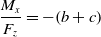 $\dfrac{M_{x}}{F_{z}}=-\!\left(b+c\right)$
. The above analysis can reflect the transformation relationship between the single-point contact state and the two-point contact state. Table III summarizes the force/moment relationships for all two-point contact states.
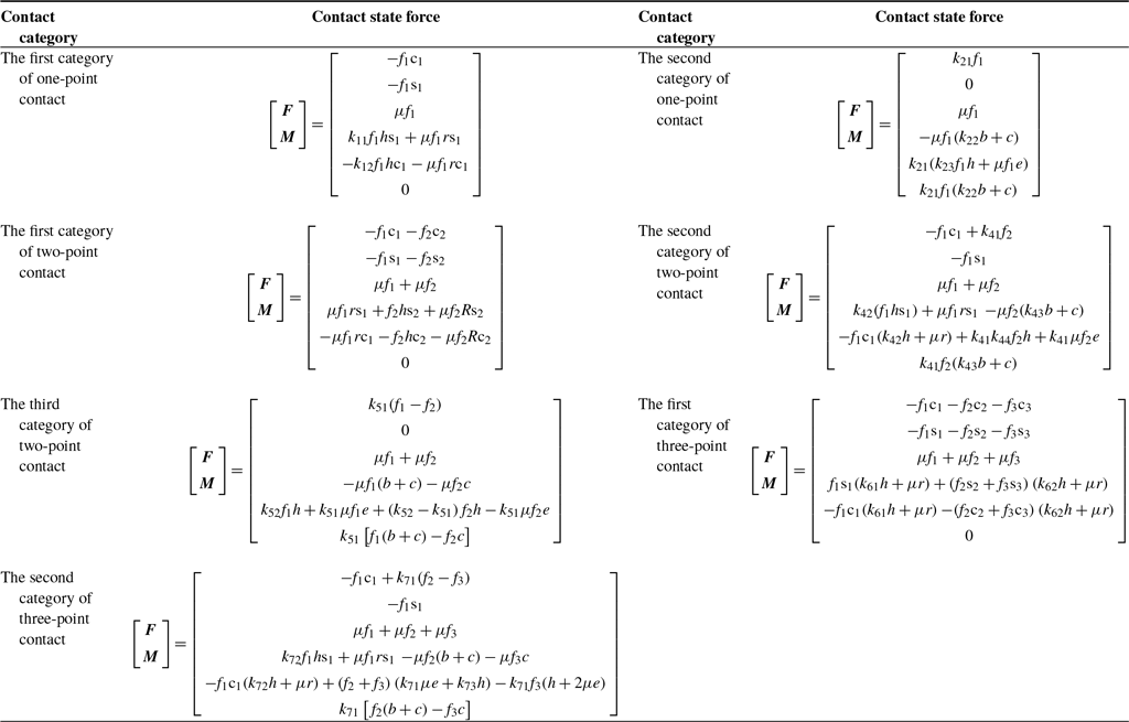
According to above analysis, the forces of other type contact state can be analyzed, as shown in Table IV.
Force/moment relationship in two-point contact.

Summary table of contact state force.

Wherein
 $k_{ij}$
is the coefficient for distinguishing different contact types under the same contact category, i = 1, 2, 3, 4, 5, 6, and 7 are the first category of one-point contact, the second category of one-point contact, the first category of two-point contact, the second category of two-point contact, the third category of two-point contact, the first category of three-point contact, and the second category of three-point contact, respectively. When
 $k_{ij}$
takes different values, the corresponding formulas can be translated into formulas for the calculation of forces of different contact types under the corresponding contact categories. For example, when
 $k_{21}=1$
,
 $k_{22}=1$
, and
 $k_{23}=1$
, the formula of the second category of one-point contact can be transformed into the force solution formula of p-1-2-1.
3. Jamming analysis
Jamming refers to a mechanical state in which the peg cannot be inserted in the hole due to the improper proportion of the force and moment applied on the peg [Reference Whitney2]. For this state, it can be eliminated by changing the applied force on peg.
3.1. Jamming diagrams
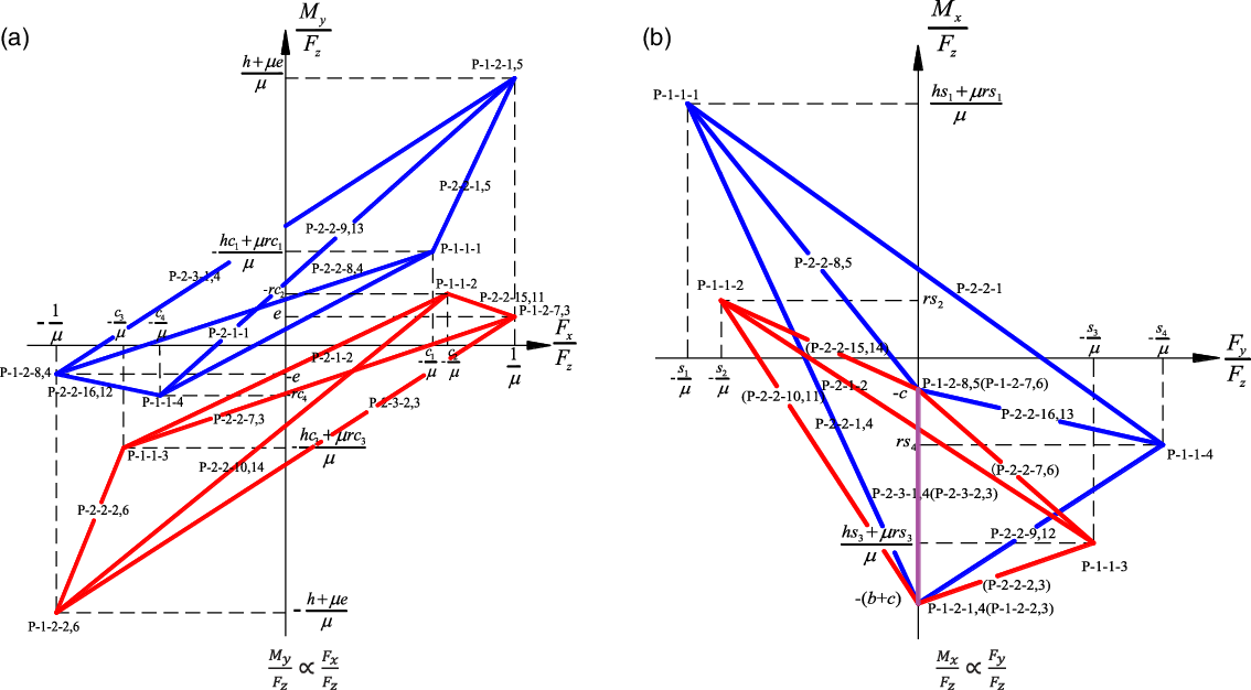
According to the force/moment relationship obtained from the above analysis, the jamming diagrams as shown in Fig. 4 can be obtained. When the force/moment conditions of all possible contact states are plotted in the force/moment space, these curves divide the force/moment space into two regions: static instability space and jamming space. The static instability space is the area surrounded by the boundary, which represents the force and moment conditions applied on the peg, and these forces/moments make the peg unstable to be inserted into the hole. On the other hand, the jamming space is the area outside the boundary. Under such force/moment conditions, the peg will fall into the jamming state, and the posture of the peg must be changed to eliminate this state. Because all one-point and two-point contact states cannot exist at the same time under specific geometric conditions, the jamming diagram representing specific insertion problems is only composed of some straight lines as shown in Fig. 3. In the following analysis, we will focus on the construction of jamming diagram for specific types of insertion problems.
Jamming diagrams.

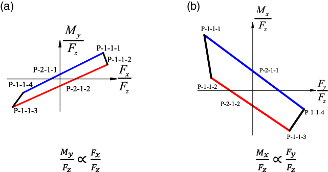
Jamming diagrams of two contact points are all in cylindrical part.

3.2. Two contact points are all in cylindrical part
The corresponding contact states of this part are the first category of one-point contact state and the first category of two-point contact state, which are all located in the cylindrical part of the composite parts.
For Fig. 5(a), if the peg contacts hole produces the contact state P-2-1-1, the moment applied on peg
 $\left| M_{y}\right|$
tends to increase, resulting in the force and moment above the blue line. It means that the peg is stuck in the hole, and the peg will not be able to continue to be inserted downward; in the same way, if the peg contacts the hole produces the contact state P-2-1-2, the moment
 $\left| M_{y}\right|$
applied to the peg will increase, resulting the force and moment below the red line. It means that the peg is stuck in the hole, and the peg will not be able to continue to be inserted downward. The picture (b) is as same as the picture (a), so the analysis should be omitted.
3.3. Two contact points are all in rectangular column part
The corresponding contact states of this part are the second category of one-point contact state and the third category of two-point contact state, which are all located in the rectangular column part of the composite part.
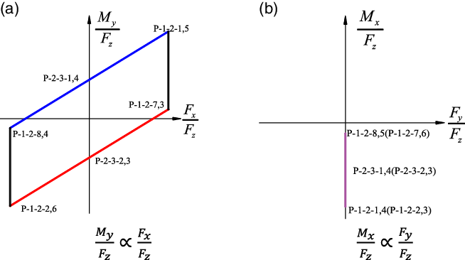
It can be seen that the jamming diagrams shown in Fig. 6 includes four kinds of jamming diagrams, which are respectively composed of contact states P-2-3-1 and P-2-3-2, P-2-3-1 and P-2-3-3, P-2-3-4 and P-2-3-2, P-2-3-4 and P-2-3-3. According to the force/moment relationship obtained from Tables II and III, the force/moment relationship expression of some contact states is same, Therefore, these jamming diagrams can be integrated as shown in Fig. 6.
Jamming diagrams of two contact points are all in rectangular column part.

As can be seen from Fig. 6(a), when the moment
 $\left| M_{y}\right|$
applied on the peg has a tendency to increase, resulting in the forces and moments above the blue line or below the red line, the assembly is stuck, and the peg cannot be inserted downward. This is the same as the jamming diagram of two contact points in the cylindrical part. However, for Fig. 6(b), the jamming diagram drawn according to the expression of force/moment relationship is a coincident straight line.
The contact state P-2-3-1 was taken for analysis. When the moment
 $\left| M_{x}\right|$
applied on the peg increases, if the cylindrical part does not contact, the peg can continue to rotate, that is, the peg will not jam. Similarly, when the force
 $\left| F_{y}\right|$
applied on the peg increases, if there is no contact of the cylindrical part, the peg can continue to move, that is, the peg will not jam. Therefore, for the contact points all located in the rectangular column part, there is no jam problem in the
 $M\_ x/F\_ z\propto F\_ y/F\_ z$
direction, so there is no jamming diagram. Consequently, the jamming diagram shown in Fig. 6(b) is not analyzed as jamming problem.
3.4. One contact point is in cylindrical part and the other is in rectangular column part
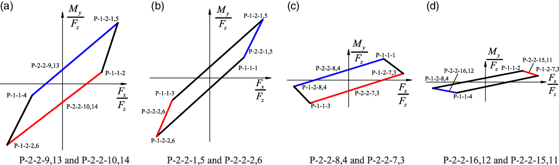
The corresponding contact states of this part are the second category of two-point contact states and two category of one-point contact states. Due to the large number of contact states, firstly, the jamming diagrams in
 $\dfrac{M_{y}}{F_{z}}\propto \dfrac{F_{x}}{F_{z}}$
direction is analyzed. According to the symmetry relationship of the contact states, the following four jamming diagrams can be obtained: one point in the cylindrical part of the composite and another point in the rectangular column part of the composite part, as shown in Fig. 7.
Jamming diagrams one contact point is in cylindrical part and the other is in rectangular column part
 $\left(\dfrac{M_{y}}{F_{z}}\propto \dfrac{F_{x}}{F_{z}}\right)$
.

It can be seen that the above four kinds of jamming diagrams have included all 16 types of contact states for the second category of two-point contact state, and according to the force/moment expressions, some of the lines of the jamming diagram are same. Therefore, in the case of one line with two kinds of contact states in Fig. 7, for the above jamming diagram, the analysis is similar to the jamming diagram of two contact points in the cylindrical part in the previous section, so it is omitted here.
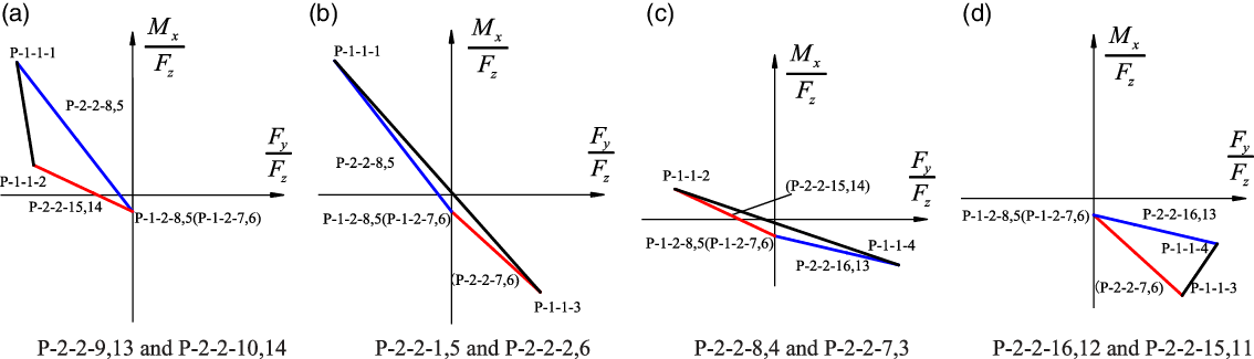
Secondly, the jamming diagram in
 $M\_ x/F\_ z\propto F\_ y/F\_ z$
direction is analyzed. Due to the particularity of the contact point in the rectangular column, the symmetrical jamming diagrams in
 $M\_ x/F\_ z\propto F\_ y/F\_ z$
direction are shown in Fig. 8.
Jamming diagrams one contact point is in cylindrical part and the other is in rectangular column part
 $\left(\dfrac{M_{y}}{F_{z}}\propto \dfrac{F_{x}}{F_{z}}\right)$
.

It can be seen that for the jamming diagrams in
 $\dfrac{M_{x}}{F_{z}}\propto \dfrac{F_{y}}{F_{z}}$
direction, due to the particularity of the force/moment relationship of the second category of one-point contact state in
 $\dfrac{M_{x}}{F_{z}}\propto \dfrac{F_{y}}{F_{z}}$
direction, the jamming diagrams in this part are different from the previous quadrilateral jamming diagram, but the triangle jamming diagrams. Although it leads to such difference, it is similar to the previous analysis in practical application, so the analysis in here is omitted.
3.5. The application of jamming diagrams
When the precise size and insertion depth of peg and hole are known, the contact state during assembly can be deduced according to the force/moment information generated in assembly, and the jamming diagrams can be deduced according to the generated contact state. In this paper, it is assumed that one-point contact state will not cause jam phenomenon, and the jam phenomenon occurs in two or more contact points. The information of force/moment applied on peg can be obtained from jamming diagrams, that is, if the force/moment applied on peg is on the straight line, it means that there will be no jam phenomenon at this time, and the assembly can continue. If the force/moment applied on peg upper or lower than the straight line, at this time, it means that the force/moment applied to the peg is greater than the expected force/moment applied to the peg. At this time, if the downward assembly continues, the assembly will be jammed and the downward insertion cannot be continued. The downward insertion action must be stopped and the peg must be withdrawn for a certain distance. According to the calculated jamming diagrams and the force/moment information applied on the peg, the position and posture of peg can be adjusted to eliminate the jamming state, and then the assembly can continue.
However, in the actual environment, without accurate measurement, the accurate size of the peg and hole cannot be obtained. It may be uneconomic and impractical to obtain the jamming diagrams for a specific problem because of the high cost of high-precision measurement process. In addition, due to the change of the contact state, the jamming diagram of a specific problem may be changed from one type to another during the insertion process, and the insertion depth needs to be monitored in real time.
4. Assembly strategy
Assembly strategy is used to plan the whole assembly process and ensure the smooth assembly of parts. In this section, we will focus on the hole searching strategy, contact state recognition strategy, and pose adjustment strategy.
4.1. Hole searching strategy
When searching holes, only the position error of the peg in the
 $x-y$
plane and the angle error around the
 $z$
-axis are considered, and the angle error on the
 $x$
-axis and
 $y$
-axis is ignored; At the same time, the center of the peg is located in a certain range of the hole. According to this, the hole searching strategy can be expressed as:
-
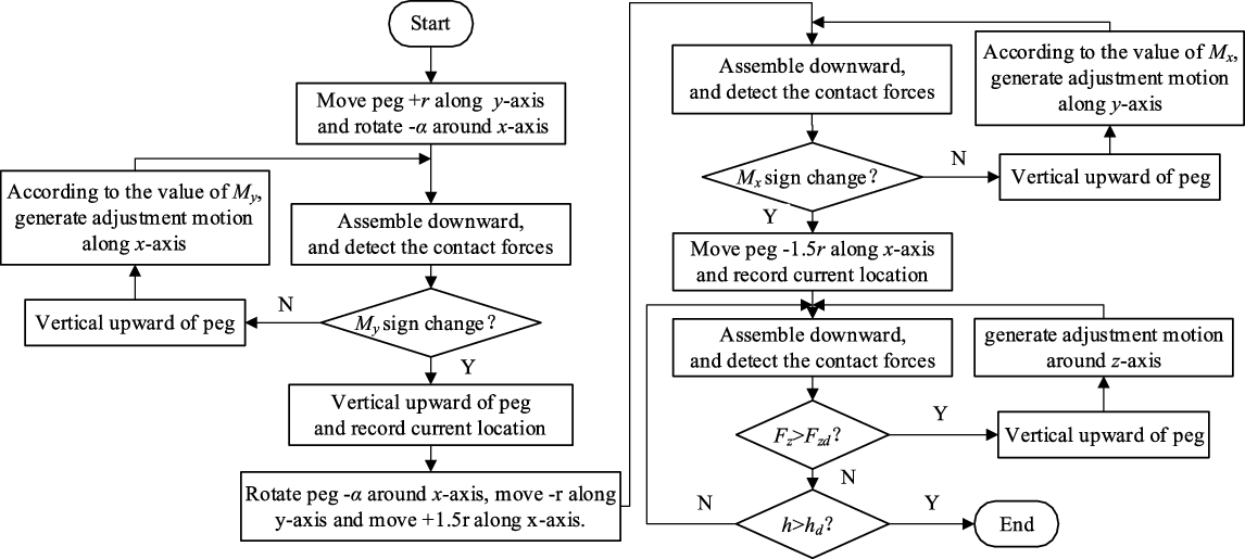
1. Initial hole searching state: move the distance with the length of r (radius of part cylindrical of peg) along the positive direction of y-axis and rotate the workpiece by a small angle α around the negative direction of x-axis.
-
2. The process of reducing the position error along the x-axis: the workpiece is assembled vertically downward, the contact force is detected through the six-dimensional force/torque sensor, and the value of My is recorded. When the value of Fz exceeds the given threshold, the workpiece moves vertically upward and disengages from contact. The controller judges whether there is a position error along the x-axis according to the value of My. If so, the controller generates adjustment motion according to the value of My, and then repeat this step. If it does not exist, the hole searching process proceeds to the next step.
-
3. Rotate the workpiece with a small angle α around the negative direction of the x-axis, then move the distance r along the negative direction of the y-axis, and then move 1.5r along the positive direction of the x-axis, and prepare for the next adjustment movement.
-
4. The process of reducing the position error along the y-axis: the workpiece is assembled vertically downward, the contact force is detected at the same time, and the value of Mx is recorded. When the value of Fz exceeds the given threshold, the workpiece moves vertically upward and disengages from contact. The controller judges whether there is a position error along the y-axis according to the value of Mx. If so, the controller generates an adjustment motion according to the value of Mx, and then repeat this step. If it does not exist, the hole searching process proceeds to the next step.
-
5. The workpiece moves 1.5r along the negative direction of the x-axis to prepare for the next adjustment movement.
-
6. The process of reducing the angle error around the z-axis: the workpiece moves vertically downward, detects the contact force at the same time, and records the values of Mx and My. If the value of Fz exceeds the given threshold, the workpiece moves vertically upward out of contact, and the controller generates an adjustment motion according to the value of Mx and My, and then repeats this step. If it moves vertically downward for a certain distance, the value of Fz does not exceed the threshold Fzd, and the assembly depth h is greater than the specified depth hd, the controller will judge that the hole searching is completed, and the assembly process enters the insertion stage.
The flow chart is shown in Fig. 9. Wherein Fx, Fy, Fz, Mx, My, and Mz are the six components of force and torque measured by the six-dimensional force/torque sensor, Fzd is the threshold value of the given force in the z-axis direction, h is the actual assembly depth, and hd is the desired assembly depth.
Flow chart of hole searching.

4.2. Contact state recognition strategy
This section will discuss contact state identification strategy to identify the contact state at a certain time in assembly. There are two steps to identify the contact state: one is to determine the current contact state category and the other is to determine the contact state type under the known contact state category. The following two aspects are studied.
-
1. Contact state category recognition strategy
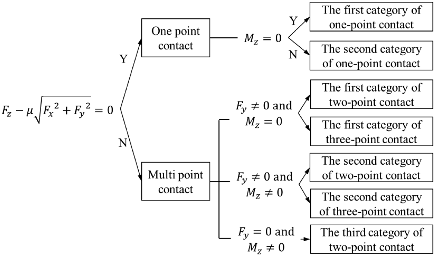
According to the force information in Table IV, for different types of contact state, the force information is also different. Therefore, the contact state can be identified according to the force information obtained by the six-dimensional force sensor. According to the force information, the recognition conditions of the contact state category are as shown in Fig. 10.
Contact state category recognition.

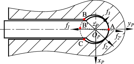
For the distinction between the first category of two-point contact state and the first category of three-point contact state, the equivalent method is adopted in this paper: without considering the friction along the
 $z$
-axis of the peg coordinate system, the three-point contact state can be equivalent to the two-point contact state, that is, the normal contact force
 $f_{2}$
on the contact point B under the three-point contact state and the normal contact force
 $f_{3}$
at the contact point C are equivalent to the normal contact force
 $f_{2}\mathrm{'}$
at B′, as shown in Fig. 11.
Schematic diagram of the first type of three-point contact equivalent to the first type of two-point contact.

When the first category of two-point contact occurs, the two contact points can only appear in the superior arc between point B and point C. When the first category of three-point contact occurs, the equivalent contact point B′ can only appear in the inferior arc between point B and point C.
Therefore, we can get the judgment conditions to distinguish the first category of two-point contact and the first category of three-point contact: when the force information meets the judgment conditions of the first category of two-point contact state and the first category of three-point contact state, we first calculate according to the first category of two-point contact state (the specific solution will be described later). If there is a contact point located in the inferior arc between point B and point C, that is, if formula (13) is satisfied, the current state can be judged as the first category of three-point contact. If the contact points are all located in the superior arc segment between points B and C, that is to say, formula (14) is satisfied, then the current state can be judged as the first category of two-point contact state:
 \begin{equation}\left| \theta _{1}+\dfrac{\pi }{2}\right| \lt {\sin} ^{-1} \dfrac{e}{r}\text{ or }\left| \theta _{2}+\dfrac{\pi }{2}\right| \lt {\sin} ^{-1} \dfrac{e}{r}\end{equation}
 \begin{equation}\left| \theta _{1}+\dfrac{\pi }{2}\right| \geq {\sin} ^{-1} \dfrac{e}{r}\text{ and }\left| \theta _{2}+\dfrac{\pi }{2}\right| \geq {\sin} ^{-1} \dfrac{e}{r}\end{equation}
For the second category of two-point contact and the second category of three-point contact, this paper uses the trial method: first, the coefficient
 $k_{41}$
,
 $k_{42}$
,
 $k_{43}\ \mathrm{and}\ k_{44}$
is calculated according to the second category of two-point contact. If the value range of the coefficient is satisfied, it is judged as the second category of two-point contact; otherwise, it is judged as the second category of three-point contact.
-
2. Contact state category recognition strategy
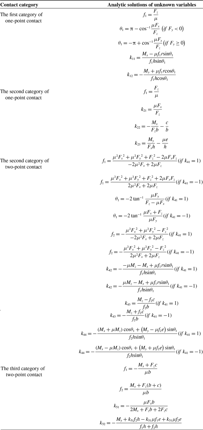
After determined the category of contact states, it is necessary to identify the types of contact states. It can be found that for different types of contact states, once the unknown parameters of contact force in each contact category are determined, the corresponding type of contact states will be determined. According to the force information
 $\left[\begin{array}{c} F_{x }\ \ F_{y}\ \ F_{z}\ \ M_{x }\ \ M_{y}\ \ M_{z} \end{array}\right]^{T}$
, the analytical solutions of the above contact types are calculated, and the results are shown in Table V.
Analytic solution of contact categories that can be solved by analytical methods.

For other contact types, it is difficult to find the analytical solution, so it is necessary to use numerical method to solve the problem. In order to improve the convergence speed and avoid iteration falling into local optimal solution, the L–M (Levenberg–Marquardt) algorithm is used as the least square optimization method. The iterative formula of L–M algorithm is as follows:
 \begin{equation}\boldsymbol{{x}}_{k+1}=\boldsymbol{{x}}_{k}-\!\left({J_{k}}^{T}J_{k}+\lambda \mathrm{I}\right)^{-1}\!\left(J_{k}\right)^{T}g\!\left(\boldsymbol{{x}}_{k}\right)\end{equation}
where
 $J_{k}$
is the gradient of function
 $g(\boldsymbol{{x}})$
at point
 $\boldsymbol{{x}}_{k}$
,
 $\lambda$
is the damping coefficient, and
 $\mathrm{I}$
is the identity matrix.
L–M algorithm itself is an unconstrained optimization method, but in this subject, because of the existence of upper and lower bounds of unknown variables, we need to consider the influence of explicit constraints in the calculation process, otherwise the final results may not conform to the actual situation. In order to solve this problem, we modify the L–M algorithm appropriately and add the part of self-checking the iteration points, that is, after each iteration, we judge whether the iteration points meet the explicit constraints. If the constraints are met, the iterative calculation will proceed normally. If not, the iteration point is modified to make it return to the feasible region, and then the iterative calculation is carried out. This modification to a certain extent sacrifices the efficiency of the original algorithm, but the advantage is that it can ensure that the iterative calculation is always carried out in the feasible region, and the final result is the optimal solution in line with the actual situation.
An example is given to illustrate the efficiency of the modified L–M algorithm. Suppose a set of valid data fed back from the six-dimensional force sensor is as follows:
 \begin{equation*} F_{x}=2.685\mathrm{N}, F_{y}=1.550\mathrm{N}, F_{z}=1.875\mathrm{N} \end{equation*}
 \begin{equation*} M_{x}=-5.423\,\mathrm{N}, M_{y}=9.392\,\mathrm{N}, M_{z}=0.000\,\mathrm{N} \end{equation*}
The values of the other parameters are as follows:
 \begin{equation*} \mu =0.25r=1\text{ mm }h=1.9\text{ mm} \end{equation*}
It is easy to distinguish the first category of two-point contact or the first category of three-point contact. Using the equivalent method, according to Table IV can be obtained:
 \begin{equation*} \left\{\begin{array}{c} -f_{1}\mathrm{c}_{1}-f_{2}\mathrm{c}_{2}-2.685=0\\[5pt] -f_{1}\mathrm{s}_{1}-f_{2}\mathrm{s}_{2}-1.550=0\\[5pt] \mu f_{1}r\mathrm{s}_{1}+f_{2}h\mathrm{s}_{2}+\mu f_{2}R\mathrm{s}_{2}+5.423=0\\[5pt] -\mu f_{1}r\mathrm{c}_{1}-f_{2}h\mathrm{c}_{2}-\mu f_{2}R\mathrm{c}_{2}-9.392=0 \end{array}\right. \end{equation*}
Constructing function:
 \begin{equation*} S\!\left(\boldsymbol{{x}}\right)={\sum }_{i=1}^{4}{g_{i}}^{2}\!\left(\boldsymbol{{x}}\right) \end{equation*}
The results show that this is the first category of two-point contact. The normal contact force and the azimuth of the contact point are shown below:
 \begin{equation*}f_{1}=2.200\mathrm{N}, f_{2}=5.300\,\mathrm{N}, \theta _{1}=30.01^{\circ}, \theta _{2}=150.00^{\circ}\end{equation*}
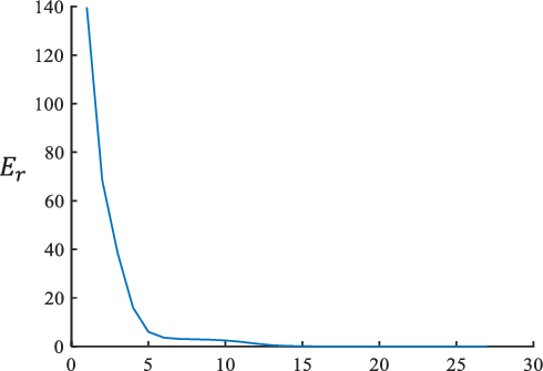
The relationship between iteration error
 $E_{r}$
and iteration number
 $t$
is shown in Fig. 12. When the number of iterations of the modified L–M algorithm reaches 20, the solution accuracy can reach
 $10^{-5}$
, the convergence speed is fast, the solution accuracy is fast, and it can meet the requirements.
The relationship between iteration error and the number of iterations.

According to the previous analysis, the following will summarize the judgment conditions of contact state recognition, as shown in Table VI.
4.3. Posture adjustment strategy
Because of the geometric complexity of assembly parts, it often produces complex contact conditions in assembly. According to the analysis above, 44 contact states may be produced when the peg is inserted. If the peg is not adjusted timely during assembly, it is likely to cause the jamming and wedging between peg and hole. Therefore, this section discussed the adjustment strategy to ensure smooth assembly.
Summary of contact state judgment conditions.

Due to the variety of contact states, it is impossible to establish a pose adjustment strategy for each contact state, and a single adjustment motion can be effective for one or more contact states. Therefore, in this paper, three kinds of basic adjustment motion are mainly applied, which are rotation around
 $x$
-axis,
 $y$
-axis, and
 $z$
-axis.
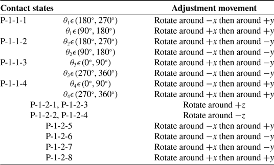
Since the contact state of two or more points can be formed by the combination of multiple one-point contact states, the adjustment strategy for one-point contact state can also be effective for multi-point contact state adjustment, so it is necessary to establish the adjustment strategy for the pose adjustment of single-point contact state. In this paper, the pose adjustment strategies for various single-point contact states are shown in Table VII.
Pose adjustment strategies.

For the posture adjustment strategy of multi-point contact states, it can be implemented according to the posture adjustment strategy of one-point contact state, that is, the multi-point contact states are divided into one-point contact states for pose adjustment, and the one-point contact state (the first category of one-point contact state) located in the circular part is preferentially adjusted. Then adjust the one-point contact state (the second category of one-point contact state) located in the rectangular part. If the pose adjustment strategy of one-point contact state composed of two or more contact states is the same, the peg is adjusted according to one-time adjustment. If the required pose adjustment direction is just the opposite, there is no need to adjust the peg in this direction.
5. Simulation
5.1. Simulation environment
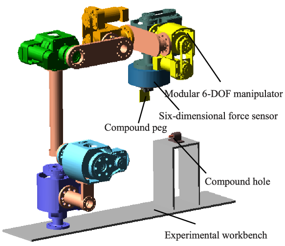
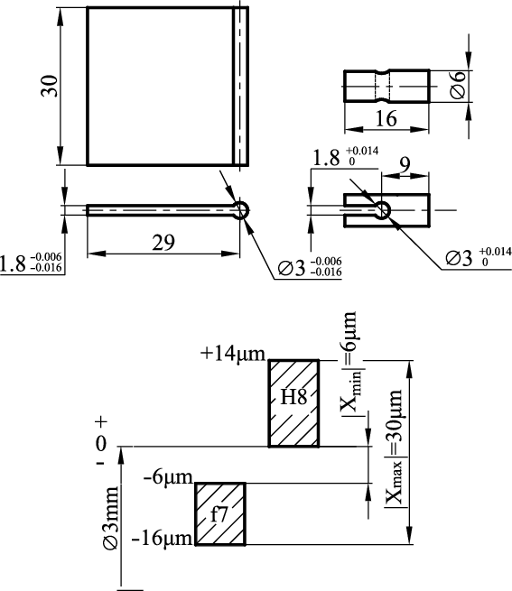
According to the existing joint modules in the laboratory, a virtual assembly environment is built in ADAMS software, as shown in Fig. 13, including a modular 6-DOF modular manipulator, a six-dimensional force sensor, and an assembly workbench. The six-dimensional force sensor is installed at the end of the manipulator, the peg is fixed on the sensor, and the hole is fixed on the experimental workbench. The dimensions and tolerance zones of the parts to be assembled are shown in Fig. 14.
Virtual prototype of 6-DOF modular manipulator.

Part size and tolerance zone.

By using the contact force analysis module in the simulation software, by setting the contact parameters, the three components of the contact force and the three components of the contact torque can be derived when the peg is in contact with the hole to simulate the function of the six-dimensional force sensor, and then the force and torque on the peg can be obtained through coordinate transformation to achieve the same effect as the six-dimensional force sensor.
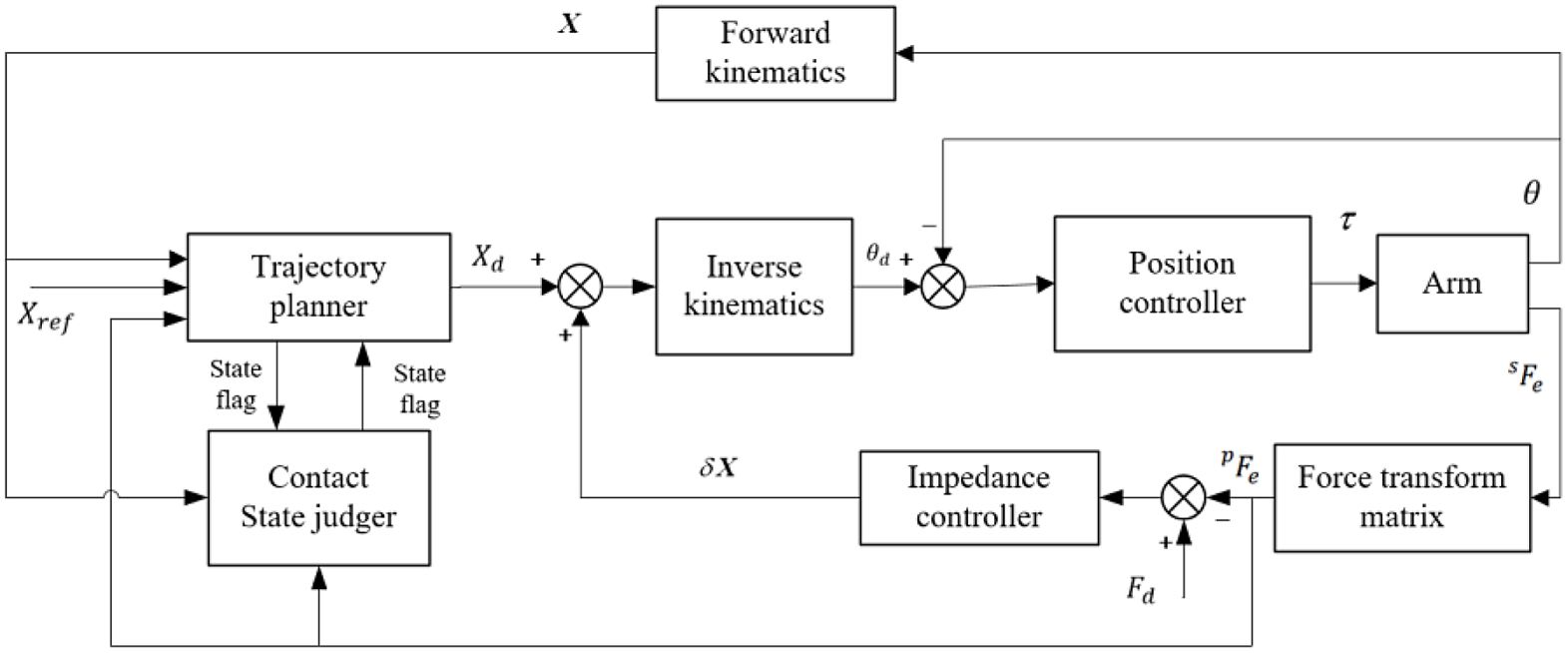
The controller is built in simulation environment, including position controller, impedance controller, contact state recognizer, and trajectory planner. The specific control block diagram is shown in Fig. 15. The inputs of the system are the reference pose
 $X_{ref}$
and the desired contact force
 $F_{d}$
. The reference pose
 $X_{ref}$
is used to give the correct pose of the peg in the peg-in-hole assembly. The trajectory planner generates the pose adjustment motion according to the reference pose, the contact force fed back by the manipulator, and the current pose and the current contact state are obtained by the contact state judge. The adjustment value of each joint is calculated through inverse kinematics and transmitted to the position controller. The desired contact force
 $F_{d}$
is used for impedance control, and the impedance controller takes the difference between
 $F_{d}$
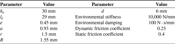
and the actual contact force as the control variable and outputs the corresponding pose adjustment value. The corresponding geometric parameters and simulation environment parameters of circular-rectangle compound peg and hole parts are shown in Table VIII.
Parameter settings.

The whole control system composition.

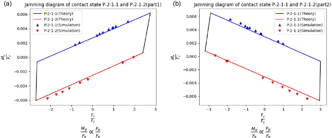
Jamming diagrams of contact state P-2-1-1 and P-2-1-2.

5.2. Simulation of assembly jamming
-
1. Two contact points all in the cylindrical part
In the simulation environment, two first category of two-point contact states which all in the cylindrical parts are simulated 10 times, respectively, and the jamming diagrams are shown in Fig. 16.
It can be seen from the jamming diagram obtained from the above simulation that almost all the forces/moment obtained from the simulation are on the straight line, which means that the assembly is in a stable insertion state at that time. At this time, although there is contact between the peg and hole, the jamming state still does not occur, and the assembly can continue downward at this time.
-
2. Two contact points all in the rectangular column part
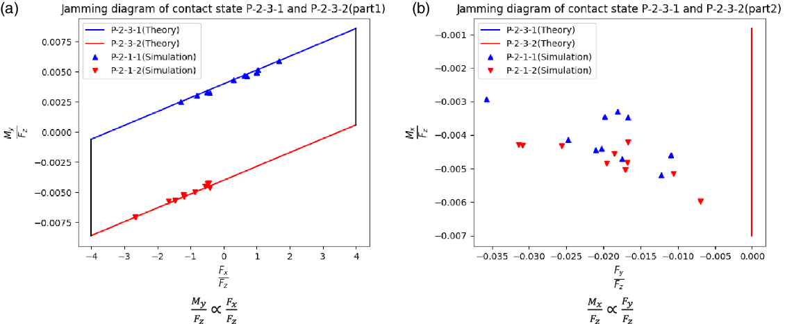
Secondly, the jamming diagram of the two contact points are located in the rectangular column are simulated and select the contact state P-2-3-1 and contact state P-2-3-2 for verification. The results are shown in Fig. 17.
Jamming diagrams of contact state P-2-3-1 and P-2-3-2.

As can be seen from the above figure, for the jamming diagram in the
 $\dfrac{M_{y}}{F_{z}}\propto \dfrac{F_{x}}{F_{z}}$
direction, it can be seen that the force/moment relationship of the generated contact state is basically on the straight line, which indicates that for the contact generated by the assembly insertion at this time, there is no jamming, and the assembly can continue. For Fig. 17(b), in theory, the force/moment relationship of the contact state should be on the straight line. However, due to the model error and force information error in the simulation environment, it is basically not on the straight line, but this part of the error can be ignored, because in the
 $\dfrac{M_{y}}{F_{z}}\propto \dfrac{F_{x}}{F_{z}}$
direction, we think that the contact state in the rectangular column does not have the problem of jamming.
-
3. One contact point is in cylindrical part and the other is in rectangular column part
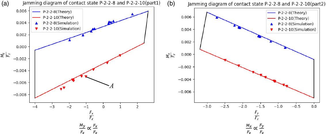
The contact state P-2-2-8 and contact state P-2-2-10 are simulated for 10 times, respectively, as shown in Fig. 18.
Jamming diagrams of contact state P-2-2-8 and P-2-2-10.

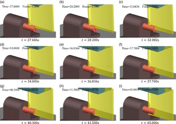
Simulation video screenshot of the insert phase.

According to Fig. 18, it can be found that the relationship calculated from the contact force information obtained by each simulation is basically located on the colored line, which also indicates that the contact state at the insertion depth should be P-2-2-9 or P-2-2-10, and some points may be outside the quadrilateral formed by two straight lines. In this paper, it is considered that the jamming state may occur, so the downward insertion must be stopped at this time. At the same time, the peg must be pulled up a certain distance. According to the generated contact state, the posture of the peg should be adjusted to eliminate the jamming state. In this figure, for the insertion process of point
 $A$
, the posture of peg should be adjusted to reduce
 $M_{y}$
. It is necessary to rotate the peg around the y-axis for a certain angle.
5.3. Simulation of assembly
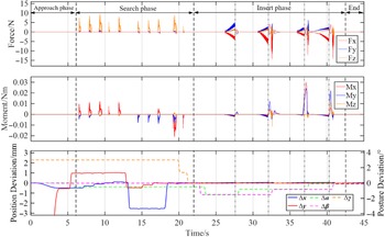
In the simulation environment, the robot successfully completes the assembly task. Some screenshots of the simulation of the insertion stage of the assembly process are shown in Fig. 19. The whole process consists of three phases. The first 6.1 s is the approaching phase, and the robot control assembly quickly approaches the hole. The 6.1 to 21.8 s is the searching phase and 21.8 to 45 s is the insertion phase. During the downward assembly process, the controller detects the contact force along the
 $z$
-axis direction in real time. When the contact force exceeds the given threshold, the contact state judger recognizes and calculates the contact state at the same time and stop the assembly movement and prepare for pose adjustment.
The force information is shown in Fig. 20. In the insertion phase, when t = 27.7 s, the contact force along z-axis exceeds the threshold, and the contact state judger calculates the contact state at this time according to the contact force and the contact moment as P-1-1-2. The azimuth of the contact point is −48.8°, and the arm stops assemble downward. The trajectory planner generates a posture adjustment plan that first rotates in the x-axis, then the y-axis in the positive direction. After a short adjustment after t = 27.7 s, the contact force decreased rapidly after a small shock.
Similarly, when the t = 32.1 s, t = 36.9 s, and t = 40.4 s, the contact force along
 $z$
-axis exceeds the given threshold, and the contact state judger calculates the contact state at this time as P-2-2-16, P-2-1-1, and P-2-2-16, the trajectory planner then generates corresponding adjustment movements to reduce the posture error between peg and hole, and the contact force and contact moment after a small oscillation quickly reduced to ensure the normal assembly. During the entire insertion phase, the maximum contact force is less than 16 N and the maximum contact torque is less than 40 N mm.
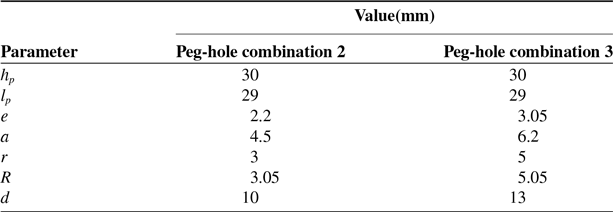
Change the diameter of the cylindrical part and the width of the square column part of the peg and hole, as shown in Table IX, and then do two sets of simulations.
Additional parameter settings

The force and moment of the peg during the assembly process.

The force and moment of the peg during the assembly process (2)

The force and moment of the peg during the assembly process (3)

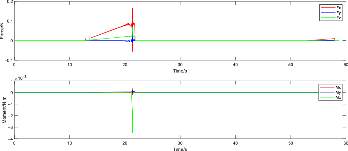
For the peg-hole combination 2, the force information of the insertion process is shown in Fig. 21. In this insertion process, there is only one contact state, i.e., at t = 20.6s, the contact state judge gets the contact state as P-1-2-3, and the trajectory planner then makes an adjustment by lifting the peg upwards for a short distance and then rotating it by a certain angle around the positive direction of the z-axis, which causes the contact force to decrease rapidly and thus allows the assembly process to continue.
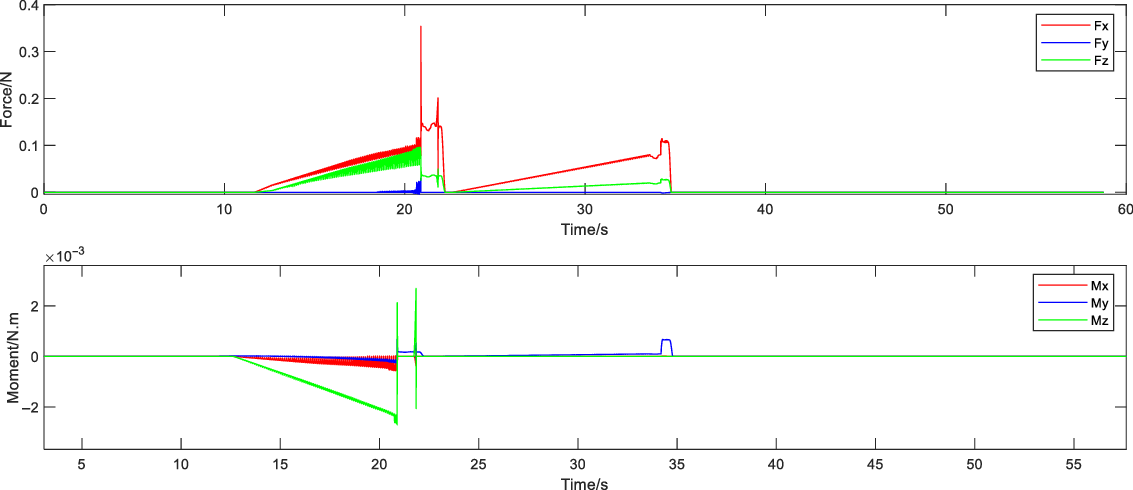
For the peg-hole combination 3, the force information of the insertion process is shown in Fig. 22. The contact state P-1-1-2 appears at both t = 21.1s and t = 33.6s, and the corresponding posture adjustment strategy is to lift the peg upward for a small distance, then rotate it by a certain angle around the negative direction of the x-axis, and then rotate it around the negative direction of the y-axis by a certain angle. The contact force gradually tends to zero after the posture adjustment, and the assembly process is successfully completed.
The results show that the contact state recognition calculation method and posture adjustment strategy proposed in this paper are effective. By identifying the contact state to generate the corresponding posture adjustment plan, combined with the impedance control, the assembly task can be realized.
6. Conclusion and future work
In this paper, the robot assembly theory of circular-rectangle compound peg and hole parts with clearance fit is deeply studied, including contact state analysis, force analysis, jamming analysis, and robot assembly process, and the correctness of the theory is verified in the simulation environment. Firstly, 44 contact states of composite parts during assembly are enumerated. Secondly, the force/moment information of maintaining each contact state is derived according to the quasi-static equilibrium condition. Thirdly, the 3D jamming diagram of composite parts assembly is given. Different parts shape and different insertion depth may produce different jamming diagrams. Through these diagrams, assembly strategies can be developed for the successful insertion of parts, and then the assembly strategy of parts is formulated. Finally, the simulation results are given, including the jamming simulation and assembly simulation. The simulation results verify the correctness of the proposed theory and realize the assembly of parts with the minimum clearance of 0.1 mm.
In the future work, we will carry out experimental research on the corresponding assembly technology to improve the above theory under the real environment of assembly, and further theoretical analysis on the possible jamming and wedging problems in the assembly process.
The research results obtained in this paper provide a new research method and important theoretical support for the automatic assembly of circular-rectangle compound peg and hole parts. The analysis method and control strategy mentioned in this paper have been well verified in the simulation environment, which plays a guiding role for the assembly of other parts with complex geometry and has important engineering practical value.
Disclosure statements
All authors of this article declare that: (1) no support, financial, or otherwise has been received from any organization that may have an interest in the submitted work; and (2) there are no other relationships or activities that could appear to have influenced the submitted work; (3) the research results of this paper are original to our research team and there is no copying.
Author contributions
The following are the contributions of the authors. Weiguo Wu proposed the idea used for the assembly of circular-rectangular compound peg and hole parts and carried out the theoretical research related to the assembly strategy, jamming analysis, etc. Kexin Liu completed the simulation of the proposed assembly strategy and performed the analysis of the results. Tong Wang completed the analysis and classification of contact states for the assembly of circular-rectangular compound peg and hole parts.