Introduction
Single-wall carbon nanotubes (SWCNTs) are one of the most distinctive cylindrical one-dimensional nanomaterials that have stimulated extensive research in multidisciplinary fields. Reference Jorio, Dresselhaus and Dresselhaus1 Besides the state-of-the-art investigations on the preparation and properties of SWCNTs in laboratories, efforts in mass production are ongoing and scalable products involving energy storage and composites are commercially available. Reference Zhang, Huang, Qian, Zhang and Wei2
Compared with arc discharge and laser ablation synthesis methods, catalytic chemical vapor deposition (CCVD) has advantages of higher capacity and simpler equipment, and has become the most prevalent method for the bulk synthesis of SWCNTs. Several manufacturers have transformed the technology from universities to produce SWCNTs in bulk with the production capacity of approximately 1.0∼1.5 ton per age (t/a). Reference Kumar and Ando3
Because many electronic and optoelectronic properties are due to the chiral structure of SWCNTs, Reference Yang, Wang, Li, Liu, Zhao, Zhang, Zhang, Yang and Li4 which is denoted by indices (n, m), chirality control is critical for higher-end applications ranging from electronics to biomedicine. Because of their good dispersion and discrete morphology, surface-grown SWCNTs provide a better platform for studying the growth mechanism and ways of controlling the synthesis. Some recent major breakthroughs have been made using surface-grown SWCNTs involving the control of chirality, Reference Sanchez-Valencia, Dienel, Groning, Shorubalko, Mueller, Jansen, Amsharov, Ruffieux and Fasel5–Reference Yang, Wang, Zhang, Yang, Luo, Xu, Wei, Wang, Xu, Peng, Li, Li, Li, Li, Bai, Ding and Li7 density, Reference Hu, Kang, Zhao, Zhong, Zhang, Yang, Wang, Lin, Li and Zhang8 length, Reference Zhang, Zhang, Zhang, Xie, Qian and Wei9,Reference Zhang, Zhang and Wei10 and conductive properties. Reference Liu and Cheng11
Catalysts play vital roles in the structure control of SWCNTs in both surface and bulk synthesis. Thermodynamically, the chirality of a SWCNT becomes locked in when the final (sixth) pentagon is added to the hemisphere during nucleation, Reference Artyukhov, Penev and Yakobson12 revealing an essential matching of symmetry between SWCNTs and the crystal surface of the catalyst particles. Reference Zhang, Kang, Wang, Tong, Yang, Wang, Qi, Deng, Li and Bai6,Reference Yang, Wang, Zhang, Yang, Luo, Xu, Wei, Wang, Xu, Peng, Li, Li, Li, Li, Bai, Ding and Li7 Kinetically, precise control of the growth conditions is crucial for prolonging the lifetime of catalyst nanoparticles in order to grow perfect, ultralong CNTs with a uniform structure. Reference Zhang, Zhang, Zhang, Xie, Qian and Wei9
The relationships between catalyst design and dispersion methods and corresponding growth mechanism are still not clear. Especially, differences between the thermodynamic characteristics and phase diagrams of the bulk catalyst and its nanoparticles, as used in SWCNT production, make mass production more complicated. The size, composition, dispersion state, and interaction with supporting materials can directly affect thermal transport, surface/bulk diffusion, and the quality of the as-grown SWCNTs. In this article, we review progress in catalyst synthesis and dispersion methods for SWCNT growth and elaborate on recent strategies for the controlled synthesis of surface and bulk SWCNTs by tailoring these catalysts.
Catalyst design for diameter-controlled growth of SWCNTs
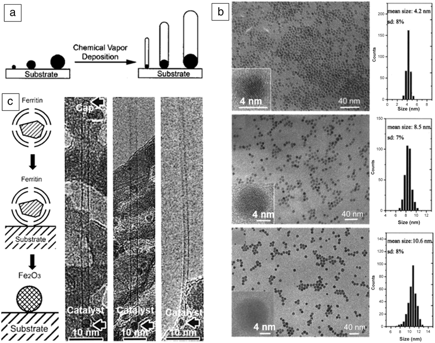
Diameter is one important parameter influencing the electronic properties of SWCNTs. Reference Saito, Fujita, Dresselhaus and Dresselhaus13 Precise control of the diameter is a primary factor for stopping the formation of metallic SWCNTs and achieving preferential growth of semiconducting SWCNTs, Reference Li, Liu, Liang, Zhou, Pierce, Wang, Peng and Liu14 both of which are essential for field-effect transistors (FETs). Therefore, the selective growth of SWCNTs with a controlled diameter, especially with an extremely narrow distribution, is important. The catalyst plays the most important role in the CVD process in determining the SWCNT diameter compared with other factors, such as temperature Reference Yao, Dai, Liu, Zhang and Liu15 and carbon feedstock. Reference Zhang, Mann, Zhang, Javey, Li, Yenilmez, Wang, McVittie, Nishi and Gibbons16 The size of the catalyst nanoparticles always has a positive correlation with the SWCNT diameter, Reference Dai, Rinzler, Nikolaev, Thess, Colbert and Smalley17–Reference Cheung, Hafner and Lieber20 as shown in Figure 1a. Therefore, methods for controlling the catalyst particle size and its stabilization during the CVD process are necessary for controlling the diameter of SWCNTs in large-scale production.
The relationship between catalysts and single-wall carbon nanotubes (SWCNTs) and the solution method to synthesize metal nanoparticles. (a) The growth of SWCNTs on catalyst nanoparticles. Reprinted with permission from Reference Cheung, Kurtz, Park and LieberReference 18. © 2002 American Chemical Society. (b) Transmission electron microscope (TEM) images of Fe–Mo nanoparticles synthesized in solution using a mixture of bis-2-ethylhexylamine and octanoic acid at different concentrations. Reference Li, Liu, Wang and Wang21 Insets are high magnification images. The plots show that increasing the amount of carboxylic acid increased the catalyst particle size (top to bottom, the extra concentrations of protective agent are 0 mmol, 2.50 mmol, and 5.00 mmol). (c) (Left) Schematic showing the preparation of discrete nanoparticles and (right) TEM images of the three different synthesized SWCNTs using different sizes of these discrete nanoparticles. Reference Li, Kim, Zhang, Rolandi, Wang and Dai22

Catalyst nanoparticles are usually obtained by reducing the corresponding precursors, so the morphology and dispersion of the precursor seriously affects the catalyst size and are important factors.
General methods to control the diameter of SWCNTs
At the early stage of controlling the SWCNT diameter, many methods have been developed to prepare homogeneous and monodispersed precursors to obtain uniform nanoparticles of the metal catalyst, such as Fe and Ni-Fe. There are three main strategies: (1) capping agent-protected synthesis of nanoparticles; (2) using special cages to trap a fixed number of metal ions to act as the catalyst precursor; and (3) using polyoxometalate (POM) nanoclusters with an identical structure as the catalyst precursor.
Capping agents attach to the surface of metal nanoparticles by coordination or static charge interactions, thus tuning the growth behavior of SWCNTs and eventually resulting in nanoparticles with a very small size and a narrow size distribution. Liu et al. obtained Fe–Mo catalysts with a size deviation as small as ∼7–8% by using a mixture of carboxylic acid and amine as the capping agent (Figure 1b) where increasing the amount of carboxylic acid increased the catalyst particle size. Reference Li, Liu, Wang and Wang21 Similarly, Lieber’s group realized diameter control of SWCNTs by changing the chain length of capping agents. Reference Cheung, Kurtz, Park and Lieber18 Other work involved using iron-storage protein, ferritin, to trap a certain number of metal ions. Dai et al. synthesized discrete catalyst particles with a tunable diameter by changing the amount of iron in ferritin, as shown in Figure 1c. Reference Li, Kim, Zhang, Rolandi, Wang and Dai22
A family of polyatomic oxyanions of transition metals (POMs [such as Mo, W, V, Nb, and Ta]) Reference Yin, Li and Liu23 are assembled with many metallic oxide polyhedra linked to each other by sharing corners and edges and therefore have definite sizes and shapes with discrete cluster structures. W and Mo are metals with high melting points, and POMs are convenient precursors for W- or Mo-containing catalysts, such as nanoparticles of monometallic Mo, bimetallic Fe-Mo, Fe-W, and W-Co. Reference Yin, Li and Liu23 Usually this method leads to a narrower particle-size distribution of the catalyst than other methods. However, for the preparation of catalysts containing Mo, correct annealing and reducing conditions are necessary because MoO3 is easily vaporized at temperatures above 600°C, and this is unfavorable for obtaining a uniform catalyst particle size. Reference Peng, Luo, Sun, Wang, Yang, Li, Yang and Li24,Reference Zhang, Tong, Hu, Kang and Zhang25 Zhang et al. used Mo catalysts prepared at a low reducing temperature and obtained semiconducting SWCNTs with a narrow diameter distribution on a quartz substrate ( Figure 2a). Reference Zhang, Tong, Hu, Kang and Zhang25 Compared with a Mo-containing cluster, W-containing nanocatalysts, shown in Figure 2b, may be a better choice since WO3 is more stable. Reference Yang, Wang, Zhang, Yang, Luo, Xu, Wei, Wang, Xu, Peng, Li, Li, Li, Li, Bai, Ding and Li7,Reference Yang, Wang, Zhang, Qi, Yang, Xu, Li, Zhao, Bai and Li26,Reference Yang, Wang, Si, Zhao, Qi, Jin, Zhang, Li, Zhang, Yang, Zhang, Xu, Peng, Bai and Li27 Undoubtedly, catalysts with a high melting point and specific size have proven to be helpful in controlling the diameter of SWCNTs.
Polyoxometalate (POM) clusters act as precursors for the formation of uniform size catalyst nanoparticles. (a) (Top) Scheme to obtain uniform Mo catalysts from Mo132 clusters at a low reducing temperature and (bottom left) the atomic force microscope (AFM) image and (bottom right) size distribution of catalysts,
Reference Zhang, Tong, Hu, Kang and Zhang25
which shows a narrow diameter distribution. (b) (Top) Co7W6 solid catalysts prepared from a POM precursor and (bottom) transmission electron microscope images with different magnifications of these solid catalysts.
Reference Yang, Wang, Zhang, Yang, Luo, Xu, Wei, Wang, Xu, Peng, Li, Li, Li, Li, Bai, Ding and Li7
 $\bar{d}$
is the geometric mean diameter. (c) (Top) Diagram of diameter-controlled growth of single-wall carbon nanotubes (SWCNTs) from SiO2 nanoparticles obtained from a 3-aminopropyltriethoxysilane (APTES)-modified substrate. (Top) Designed process and (bottom) different AFM images of catalysts on the substrate modified by different concentrations of APTES.
Reference Chen and Zhang29
Note: CVD, chemical vapor deposition; EtOH, ethanol.

When a dispersion solution of catalyst nanoparticles is dropped on a substrate, they tend to aggregate and form random agglomerates, which does not help produce uniform catalyst nanoparticles. Liu et al. modified a silicon dioxide surface using 3-aminopropyltriethoxysilane (APTES). Reference Chen, Xu, Zhang and Huang28 The modified surface terminated by amine groups becomes positively charged, such that negatively charged species assemble on the surface through Coulombic attraction. Alkyl amine and alkyl carboxylic acid capped Fe–Mo nanoparticles can be uniformly distributed on these substrates. Reference Chen, Xu, Zhang and Huang28 Coincidently, Zhang’s group directly grew SWCNTs on a silicon dioxide surface that had been modified by APTES and found that the diameter distribution of the nanotubes correlated with that of the SiO2 nanoparticles (Figure 2c). Reference Chen and Zhang29 The size of the SiO2 nanoparticles was increased by increasing the number of APTES layers deposited on the silicon dioxide surface, thus producing a larger SWCNT diameter.
Specific methods for controlling the diameter of SWCNTs in a horizontal array
On a flat substrate there are two main processes that affect the size distribution of catalyst nanoparticles, aggregation occurring in the calcination and reduction processes and Ostwald ripening in the reduction and CVD processes. In Ostwald ripening, larger nanoparticles grow at the expense of small nanoparticles. These two effects make it difficult to obtain a SWCNT horizontal array with a narrow diameter distribution because they lead to nanoparticles with a broader size distribution, which is unfavorable for the growth of SWCNTs with a uniform diameter. However, strong interaction between the catalyst nanoparticles and the substrate will help retain the narrow size distribution of the catalytic nanoparticles. To strengthen this interaction, thermal annealing is used.
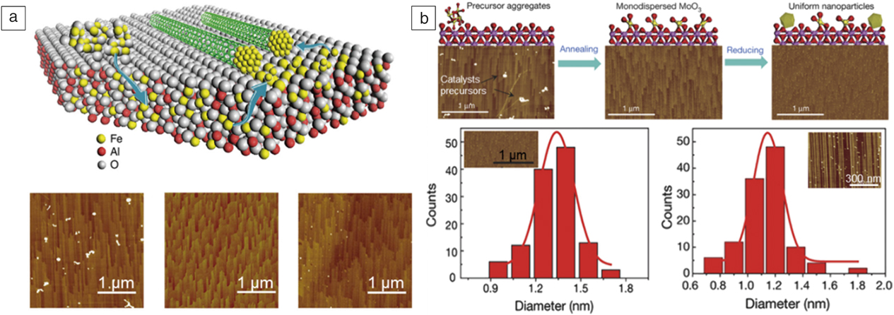
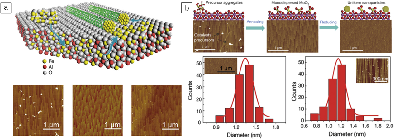
Ago et al. found that thermal annealing in an ultrahigh vacuum followed by H2 reduction for 1 h resulted in catalyst nanoparticles with a narrow size distribution. Reference Ago, Ayagaki, Ogawa and Tsuji30 Using these catalysts, horizontally aligned SWCNTs with a very narrow diameter distribution, 76% of which have diameters between 1.3 and 1.4 nm, were obtained. Zhang et al. designed a special annealing process at a temperature of ∼1100°C that buries Fe2O3 in the sapphire substrate Reference Hu, Kang, Zhao, Zhong, Zhang, Yang, Wang, Lin, Li and Zhang8 to reduce catalyst aggregation. Since Fe2O3 has a similar crystal structure to sapphire, Al3+ can be partially replaced by Fe3+ in the sapphire substrate due to the entropy effect. As shown in Figure 3a, Reference Hu, Kang, Zhao, Zhong, Zhang, Yang, Wang, Lin, Li and Zhang8 by introducing hydrogen, Fe3+ ions were reduced and released from the substrate, forming the active catalyst to grow SWCNTs. Because of the strong interaction between the freshly formed catalyst particles, named “Trojan catalysts,” and the sapphire substrate, aggregation was avoided, and a horizontal SWCNT array with an ultrahigh density of ∼130 tubes/μm was obtained. Zhang’s group modified this process Reference Zhang, Kang, Wang, Tong, Yang, Wang, Qi, Deng, Li and Bai6 to improve the uniformity of the particles. As shown in Figure 3b, Reference Zhang, Kang, Wang, Tong, Yang, Wang, Qi, Deng, Li and Bai6 monodispersed MoO3 formed on sapphire through an annealing process. Using a lower reducing temperature, they slowed the reducing rate and thus produced Mo2C catalyst particles of uniform size, with nearly 90% of the particles having diameters between 1.1 nm and 1.5 nm. Since Mo2C has a high melting point and, therefore, a lower vapor pressure, aggregation and Ostwald ripening were largely suppressed. This method was also used to prepare uniform solid WC catalysts with a small size. These uniform carbide catalysts were used to synthesize (2n, n) type SWCNTs. Reference Zhang, Kang, Wang, Tong, Yang, Wang, Qi, Deng, Li and Bai6
Enhancing the interaction between catalysts and substrate to realize diameter-controlled growth of single-wall carbon nanotubes (SWCNTs). (a) (Top) Schematic of the growth of high-density horizontal SWCNT arrays (green) by reducing Fe buried into the substrate to suppress aggregation, and the catalysts obtained by this process are named Trojan catalysts. (Bottom) Atomic force microscope (AFM) images of substrates during different periods (left to right: before annealing, after annealing, and after reducing in hydrogen). Reference Hu, Kang, Zhao, Zhong, Zhang, Yang, Wang, Lin, Li and Zhang8 (b) (Top) Schematic of the process to obtain uniform size catalysts to grow (12, 6) tubes using monodispersed MoO3 on a sapphire substrate. (Bottom) Size distributions of (left) catalysts and (right) SWCNTs. The insets are AFM images of the (left) catalysts and (right) SWCNTs. Reference Zhang, Kang, Wang, Tong, Yang, Wang, Qi, Deng, Li and Bai6
In summary, the diameter of the SWCNTs highly depends on the size of the catalyst particles. To achieve diameter-controlled growth of SWCNTs by CVD, a rational choice and design of the catalyst as well as the supporting substrates is necessary to maintain uniform size of the catalyst nanoparticles.
Chirality-controlled growth of SWCNTs
Chirality-specific SWCNTs have shown outstanding performance in many applications such as high-resolution multicolor biological imaging, Reference Yomogida, Tanaka, Zhang, Yudasaka, Wei and Kataura31 high-efficiency photovoltaic processes, Reference Jain, Howden, Tvrdy, Shimizu, Hilmer, McNicholas, Gleason and Strano32,Reference Isborn, Tang, Martini, Johnson, Otero-de-la-Roza and Tung33 and photocatalytic water splitting. Reference Murakami, Tango, Miyake, Tajima, Nishina, Kurashige, Negishi and Takaguchi34 To prepare chirality-specific SWCNTs, researchers have made significant efforts in the past two decades. Reference Zhang, Hou, Liu and Cheng35,Reference Li, Liu, Zhao, Yang, Wang and Li36 The formation process of a SWCNT has been observed with TEM and has shown that carbon caps first nucleate on the catalyst, then grow into well-defined tubes by the addition of more carbon atoms. Reference Dai, Rinzler, Nikolaev, Thess, Colbert and Smalley17 Therefore, the SWCNT chirality is directly related to the structure of the carbon cap and can even be determined by the structure of the cap with a suitable and stable carbon supply.
Chirality-controlled growth of SWCNTs by catalysts supported on flat substrates
There are two approaches to achieve chirality selective growth of SWCNTs. One is epitaxial growth SWCNT from well-defined SWCNT segments, such as segments of SWCNTs with specific chirality and caps from opening fullerenes or cyclodehydrogenation of polycyclic hydrocarbon precursors. The Smalley group used SWCNTs with metal nanoparticles docked on the open ends as the catalysts to restart the SWCNT growth. Reference Wang, Kim, Shan, Kittrell, Fan, Ericson, Hwang, Arepalli, Hauge and Smalley37 The produced SWCNTs thus had the same chirality as the seed tubes. Ultrashort capped (6, 6) nanotubes were synthesized by Pt-catalyzed cyclodehydrogenation of the well-designed polycyclic hydrocarbon precursor C96H54. Reference Sanchez-Valencia, Dienel, Groning, Shorubalko, Mueller, Jansen, Amsharov, Ruffieux and Fasel5 The resultant ultrashort capped (6, 6) nanotubes were elongated into long SWCNTs with the same chirality through the incorporation of more carbon atoms. The use of SWCNT seeds to achieve chirality-controlled growth of SWCNTs has made great progress, but increasing the stability of the seeds and the yield and efficiency of SWCNT production remains a challenge.
The second method is to control the structure of the SWCNT cap though catalyst-epitaxial growth, since theoretical simulation has demonstrated that lattice-matched caps are more stable. Reference Reich, Li and Robertson38 Fouquet et al. realized the dominant growth of (6, 5) SWCNTs with an abundance of 27% from a Co catalyst on an oxidized Si wafer. Reference Fouquet, Bayer, Esconjauregui, Blume, Warner, Hofmann, Schlögl, Thomsen and Robertson39 The selectivity was attributed to the homogeneous Co catalyst nanoparticles stabilized by interfacial Co–Si interactions. Preferential growth of (16, 2) tubes was achieved using Co-Mo catalysts on the (1 1 -2 0) plane of sapphire, while SWCNTs grown on the (1 -1 0 2) plane are dominated by the near-armchair SWCNTs. Reference Ishigami, Ago, Imamoto, Tsuji, Iakoubovskii and Minami40 They speculated that the different atomic structures of the (1 1 -2 0) and (1 -1 0 2) plane sapphire surfaces induced different morphologies and orientations of the catalysts, which then influenced the SWCNT chirality. Great efforts have been devoted to improve the chiral selectivity of the SWCNTs though regulating the catalyst size, composition, and morphology. Nevertheless, chiral selectivity of SWCNTs is still far from satisfactory.
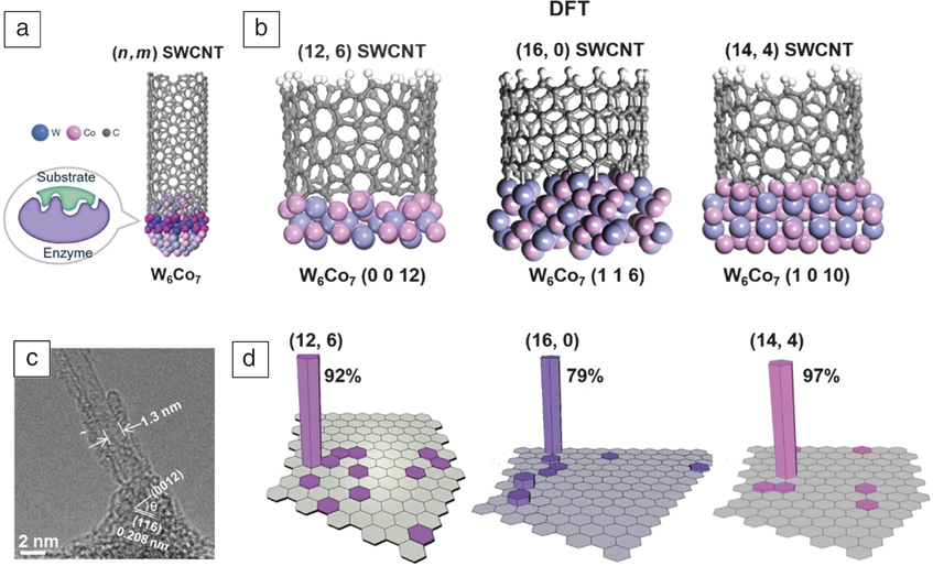
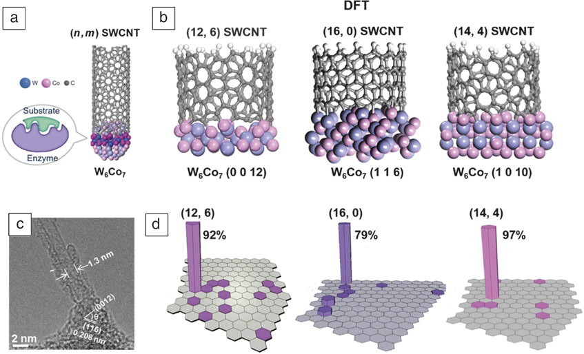
Li et al., inspired by the extremely high selectivity of enzyme-catalyzed reactions endowed by the molecular recognition effect, proposed that a solid catalyst with low crystal symmetry and a unique atomic arrangement can epitaxially grow a SWCNT with a designed chirality ( Figure 4a). Reference Yang, Wang, Li, Liu, Zhao, Zhang, Zhang, Yang and Li4 Tungsten-based intermetallic compounds with a rhombohedral structure were considered suitable candidates for this purpose. W tends to give the catalyst a high melting point and retain its crystalline structure during the CVD process while other components (Fe, Co, and Ni) provide the correct catalytic activity for SWCNT growth. In situ high-resolution (HR)TEM observations at 1100°C proved that W6Co7 nanoparticles maintained their crystal structure. Reference Yang, Wang, Zhang, Yang, Luo, Xu, Wei, Wang, Xu, Peng, Li, Li, Li, Li, Bai, Ding and Li7 In addition to a high melting point, the crystalline symmetry of the rhombohedral W6Co7 was low, both of which help the catalyst offer a structure to specifically recognize SWCNTs with different chiralities. Density functional theory (DFT) simulations indicated that the (0 0 12) W6Co7 plane perfectly matches the (12, 6) tube (Figure 4b). With a W6Co7 catalyst prepared at 1030°C, (12, 6) tubes were obtained at an abundance of 92% (Figure 4d). Reference Yang, Wang, Zhang, Yang, Luo, Xu, Wei, Wang, Xu, Peng, Li, Li, Li, Li, Bai, Ding and Li7 HRTEM images of the SWCNT–catalyst interfaces showed that the (12, 6) tubes were always perpendicular to the (0 0 12) plane of the W6Co7 catalyst (Figure 4c). Reference Yang, Wang, Li, Liu, Zhao, Zhang, Zhang, Yang and Li4 Furthermore, DFT simulations also revealed that (16, 0) tubes and (14, 4) tubes match the atomic arrangements of (1 1 6) plane and (1 0 10) plane of W6Co7, respectively, (Figure 4b). Reference Yang, Wang, Zhang, Qi, Yang, Xu, Li, Zhao, Bai and Li26,Reference Yang, Wang, Si, Zhao, Qi, Jin, Zhang, Li, Zhang, Yang, Zhang, Xu, Peng, Bai and Li27 The dominant growth of (16, 0) and (14, 4) tubes with the purity of 79% and 97%, respectively, were therefore realized at an optimized growth conditions (Figure 4d). Reference Yang, Wang, Zhang, Qi, Yang, Xu, Li, Zhao, Bai and Li26,Reference Yang, Wang, Si, Zhao, Qi, Jin, Zhang, Li, Zhang, Yang, Zhang, Xu, Peng, Bai and Li27 A high melting point, low crystalline symmetry, and suitable catalytic activity are indispensable for catalysts designed to give chirality-selective growth of SWCNTs. Maruyama’s group also realized the selective synthesis of (12, 6) with an enrichment of 50–70% using sputtered Co-W as the catalyst. Reference An, Kumamoto, Takezaki, Ohyama, Qian, Inoue, Ikuhara, Chiashi, Xiang and Maruyama41
(a) A schematic of an enzyme-catalyzed reaction and templated growth of a single-wall carbon nanotube (SWCNT) with specific chirality by W6Co7 catalyst. Reference Yang, Wang, Li, Liu, Zhao, Zhang, Zhang, Yang and Li4 (b) Density functional theory (DFT) simulation of SWCNTs on W6Co7 nanocrystal. Side views of interfaces between the (12, 6) SWCNT and (0 0 12) plane of W6Co7 catalyst, the (16, 0) SWCNT and (1 1 6) plane of W6Co7 catalyst, and (14, 4) SWCNT and the (1 0 10) plane of W6Co7 catalyst. Reference Yang, Wang, Zhang, Yang, Luo, Xu, Wei, Wang, Xu, Peng, Li, Li, Li, Li, Bai, Ding and Li7,Reference Yang, Wang, Zhang, Qi, Yang, Xu, Li, Zhao, Bai and Li26,Reference Yang, Wang, Si, Zhao, Qi, Jin, Zhang, Li, Zhang, Yang, Zhang, Xu, Peng, Bai and Li27 (c) High-resolution transmission electron microscope image of a (12, 6) SWCNT around the (0 0 12) plane of a W6Co7 nanocrystal. Reference Yang, Wang, Zhang, Yang, Luo, Xu, Wei, Wang, Xu, Peng, Li, Li, Li, Li, Bai, Ding and Li7 (d) Relative abundances of various chiralities from Raman measurements denoted in a partial SWCNT chiral map. Reference Yang, Wang, Zhang, Yang, Luo, Xu, Wei, Wang, Xu, Peng, Li, Li, Li, Li, Bai, Ding and Li7,Reference Yang, Wang, Zhang, Qi, Yang, Xu, Li, Zhao, Bai and Li26,Reference Yang, Wang, Si, Zhao, Qi, Jin, Zhang, Li, Zhang, Yang, Zhang, Xu, Peng, Bai and Li27 Note: n, m; chiral indices.
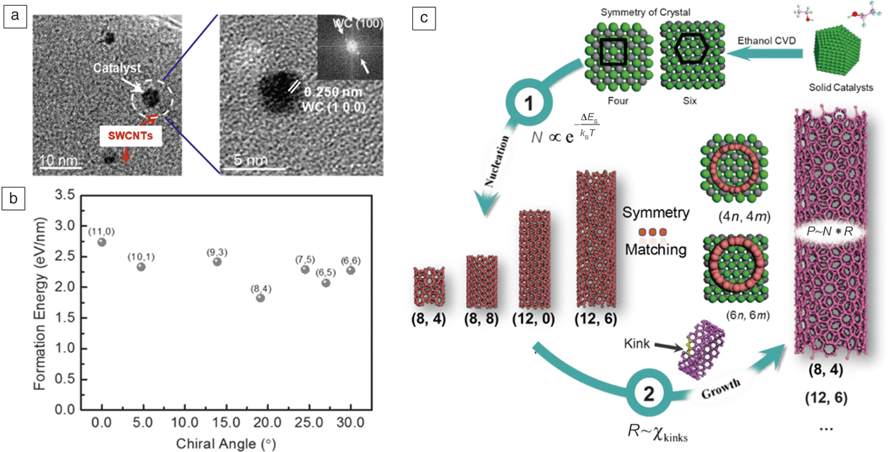
Other than the atomic-level structural match, Zhang’s group proposed a symmetry matching model based on the experimental results shown in Figure 5a. Reference Zhang, Kang, Wang, Tong, Yang, Wang, Qi, Deng, Li and Bai6 The edge of the SWCNTs and plane of the catalyst share a similar symmetry in thermodynamics, which was also proved by theoretical calculations (Figure 5b). They further optimized the kinetic growth conditions after considering the growth rate for different carbon nanotubes. Eventually, they obtained a sixfold symmetry (12, 6) nanotube array using sixfold Mo2C catalysts and fourfold symmetry (8, 4) nanotubes from fourfold (1 0 0) WC catalysts, as shown in Figure 5c. Reference Zhang, Kang, Wang, Tong, Yang, Wang, Qi, Deng, Li and Bai6
Thermodynamics and kinetics principle put forward to control the chirality of single-wall carbon nanotubes (SWCNTs). (a) A tube grown from a WC (1 0 0) plane proved by the transmission electron microscope (TEM) and the inset is the corresponding Fourier transform pattern of high-resolution transmission electron microscope images on right. (b) Theoretical calculation results showed the symmetry matching between the edges of different tubes and the WC catalyst (1 0 0) plane would lead to the lowest formation energies of the tubes on this solid catalysts plane. (c) Two-step control of the chirality of SWCNTs in ethanol chemical vapor deposition (CVD): (1) symmetry matching between the nanotubes and solid catalysts and (2) optimizing the kinetic growth condition according to the number of screw dislocations (kinks). Note: N, nucleation possibility of SWCNTs; k B, Boltzmann constant; T, growth temperature; P, population of SWCNTs with specific chirality; R, kinetics growth rate; n and m are the integers (n > m); χkinks, number of kinks; and ΔE s, energy difference led by the symmetry matching. Reference Zhang, Kang, Wang, Tong, Yang, Wang, Qi, Deng, Li and Bai6

Chirality-controlled growth of SWCNTs by supported catalysts on porous substrates
In the heterogeneous catalyst industry, catalysts are commonly loaded onto a porous substrate because the substrate has a large specific surface area that can load more catalyst, thus improving the yield of SWCNTs. Furthermore, the interactions between metal catalysts and porous substrates are usually stronger than those with a flat substrate. This strong interaction allows the catalysts to avoid sintering and keep their uniformity.
Porous or mesoporous SiO2, porous MgO, and zeolite are commonly used porous substrates for the growth of SWCNTs. Reference Wang, Yuan, Wei, Goh, Yu and Chen42 It is obvious that the selection of the substrate will directly influence the formation of the catalyst and thus affect the growth of SWCNTs. Kauppinen et al. used SiO2-supported Co as the catalyst and realized the selective growth of (6, 5) SWCNTs. Reference He, Chernov, Fedotov, Obraztsova, Rikkinen, Zhu, Sainio, Jiang, Nasibulin, Kauppinen, Niemelä and Krause43 The interaction between cobalt and the substrate facilitated the formation of uniform subnanometer Co catalysts, which favored the formation of small diameter SWCNTs. Reference Li, Wang, Derrouiche, Haller and Pfefferle44 Porous MgO was also used as the substrate for Co catalyst. FCC Co nanoparticles formed in CO through lattice-mismatched epitaxy from the Co x Mg1–x O solid solution. Meanwhile, due to strong interaction between Co2+ and MgO in the solid solution, only Co2+ in the first few top atomic layers was reduced, thus forming uniform, small-sized Co nanoparticles, which contributed to the preferential growth of (6, 5) with 53% purity. Reference He, Jiang, Liu, Fedotov, Chernov, Obraztsova, Cavalca, Wagner, Hansen, Anoshkin, Obraztsova, Belkin, Sairanen, Nasibulin, Lehtonen and Kauppinen45
In addition to the substrate, researchers also controlled the size and structure of the catalyst by introducing other metallic components to achieve chiral selective growth. Resasco et al. obtained (6, 5) SWCNTs with a purity of 54% using SiO2-supported CoMo catalysts. Reference Lolli, Zhang, Balzano, Sakulchaicharoen, Tan and Resasco46 The interactions between Mo oxides and Co stabilized the Co catalyst against aggregation, so the size of Co nanoparticles was small and uniform, which contributed to the preferential growth of (6, 5). Reference Bachilo, Balzano, Herrera, Pompeo, Resasco and Weisman47 Similar results were also obtained for FeCu, Reference He, Chernov, Fedotov, Obraztsova, Sainio, Rikkinen, Jiang, Zhu, Tian and Kauppinen48,Reference He, Liu, Chernov, Obraztsova, Kauppi, Jiang, Anoshkin, Cavalca, Hansen, Wagner, Nasibulin, Kauppinen, Linnekoski, Niemelä and Lehtonen49 CoMn, Reference Loebick, Derrouiche, Marinkovic, Wang, Hennrich, Kappes, Haller and Pfefferle50 CoCr, Reference Zoican Loebick, Derrouiche, Fang, Li, Haller and Pfefferle51 FeMn, Reference He, Fedotov, Chernov, Obraztsova, Jiang, Wei, Cui, Sainio, Zhang, Jin, Karppinen, Kauppinen and Loiseau52 and CoPt Reference Liu, Ren, Li, Liu and Cheng53 catalysts. The involvement of uniform intermediates is an additional strategy to obtain catalyst nanoparticles with a narrow size distribution for chirality-selective growth of SWCNTs. Reference Wang, Wang, Quek, Wei, Zhao, Li, Chan-Park, Yang and Chen54,Reference Yuan, Karahan, Yıldırım, Wei, Birer, Zhai, Lau and Chen55
Catalysts for the bulk synthesis of SWCNTs
Synthesis, dispersion, and evaluation of the catalysts
Supported catalyst and free catalyst
Both supported and free catalysts have been used in synthesizing bulk CNTs. Catalysts can be preloaded onto a porous or flat substrate to grow CNTs. It has been reported that aligned CNTs can be synthesized in zeolite Reference Kumar and Ando56 or gel Reference Li, Xie, Qian, Chang, Zou, Zhou, Zhao and Wang57 templates with catalysts well dispersed in the nanopores. For the growth of SWCNTs on flat substrates, catalyst nanoparticles or catalyst precursors are deposited on the substrates by solution routes Reference Zhang, Zhang, Zhang, Xie, Qian and Wei9,Reference Zhu, Wei, Xie, Zhang, Bai, Wang, Zhang, Wang, Peng, Dai and Wei58,Reference Wang, Li, Xie, Jin, Wang, Li, Jiang and Fan59 or sputtering. The supported catalysts often offer precise control of the size, composition, and morphology of the particles.
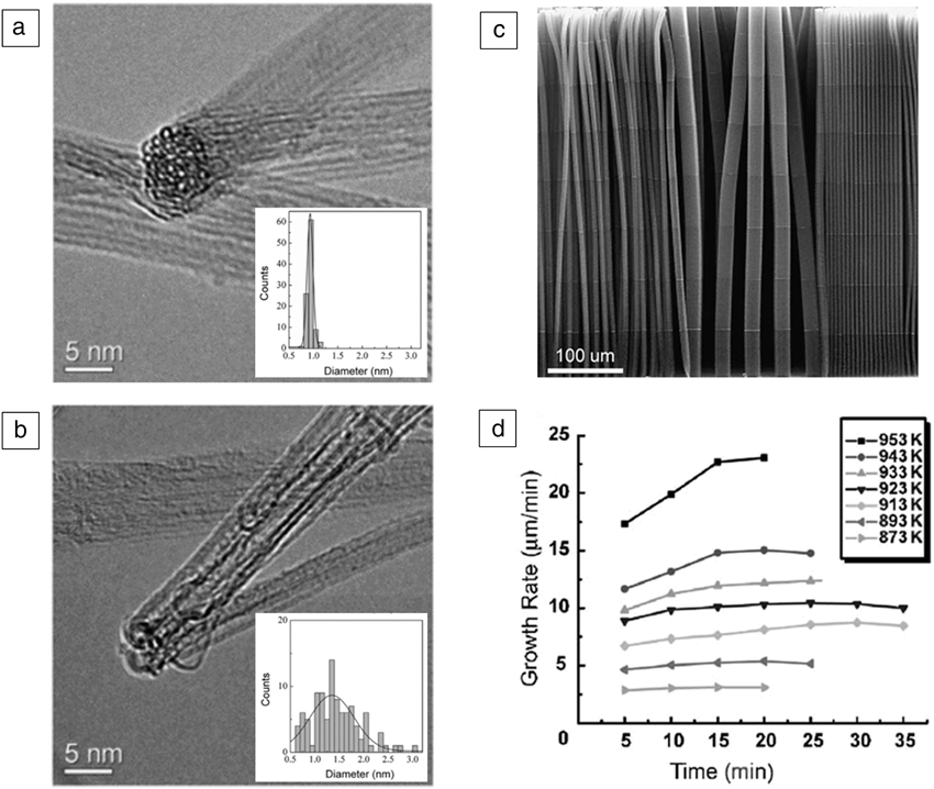
A free catalyst features simultaneous formation of catalyst particles and the carbon feed source, which is more suitable for the continuous and bulk synthesis of CNTs. Wei’s group have used this method in a designed nano-agglomerate fluidized-bed reactor, achieving bulk synthesis of aligned CNTs with a yield of 3 kg/h. Reference Zhang, Zhao, Huang, Nie and Wei60 The product is now commercially available at CNano Technology Limited (China), however, a notable disadvantage is the difficulty in controlling the CNT diameter. Ago et al. proposed a method to narrow the diameter distribution by lowering the Fe loading on Fe/MgO catalysts Reference Ago, Imamura, Okazaki, Saito, Yumura and Tsuji61 ( Figure 6a–b). This was attributed to the smaller catalyst particles formed when the metal loading amount was low, and the dominating surface diffusion on the catalyst particles resulted in the selective formation of SWCNTs. Reference Zhang, Huang, Zhao, Qian and Wei62 Despite that, further research is needed to precisely control the size and dispersion of catalyst particles for the stable bulk synthesis of CNTs.
(a–b) Transmission electron microscope (TEM) images of single-wall carbon nanotubes (SWCNTs) grown over (a) 0.6 wt% and (b) 3 wt% Fe supported on porous MgO. Reprinted with permission from Reference Ago, Imamura, Okazaki, Saito, Yumura and TsujiReference 61. © 2005 American Chemical Society. Insets, histograms of the outer diameter of CNTs determined from TEM images. At 0.6 wt%, only SWCNTs were observed, while 3 wt% loadings gave 74% SWCNTs. The outer diameter exhibits a wider distribution with increased Fe loading. (c) Scanning electron microscope image of as-grown marked carbon nanotube (CNT) array formed through a sequential shortage of carbon feedstock. The growth rate can be obtained by measuring the distance between lines with the known time sequences. (d) Measured growth rates plotted against time at different temperatures ranging from 873 K to 953 K. At relatively low temperature, the growth rate is almost constant while at relatively high temperature, CNT growth accelerates before entering steady state with a constant growth rate. (c–d) Reprinted with permission from Reference Liu, Jiang, Feng, Chen and FanReference 63. © 2005 Elsevier.

Catalyst lifetime
The lifetime is a key characteristic among catalyst properties, especially for growing long CNTs. The lifetime of the catalyst is highly dependent on the reaction conditions. Liu’s group developed a method to introduce marks on CNTs by reducing the carbon source concentration at designed times, Reference Liu, Jiang, Feng, Chen and Fan63 which can be post-identified and facilitate subsequent study of the kinetics (Figure 6c–d). Another approach involves an isotope labeling technique, Reference Liu and Fan64 where 12C and 13C ethylene gases were fed into the reactor to reveal the growth mechanism and the growth rate.
Effects of support materials on the catalysts and bulk SWCNT growth
Conventional support materials and interactions with catalysts
The commonly used support materials in CVD include SiO2, Al2O3, MgO, CaO, ZrO2, TiO2, and graphite. The choice of support material and catalyst determines the quality and yield of the as-grown SWCNTs, as shown by the following relationships: (1) Only certain combinations of catalyst and substrate contribute significantly to SWCNT growth, such as Fe on Al2O3 or SiO2, Co on MgO or Al2O3, and Ni-Co on silica; Reference Harutyunyan65 (2) Inappropriate combinations of catalyst–and substrate decrease the catalytic activity; and (3) the catalyst–substrate interaction strongly affects the melting temperature of catalyst particles and thus the growth of SWCNTs. These catalyst–substrate relationships are attributed to their physical and chemical interactions. Physical interactions induced by van der Waals and electrostatic forces reduce the mobility of catalyst particles. For example, the theoretical study shows that supported catalysts possess higher melting temperatures than the free catalysts owing to reduced surface curvature in the former. Reference Jiang, Awasthi, Kolmogorov, Setyawan, Börjesson, Bolton, Harutyunyan and Curtarolo66
Meanwhile, there may be chemical interactions involving charge transfer and even reactions between catalysts and some substrates. Some supports such as oxide substrates are beneficial for not only SWCNT growth, but also the ultrafast growth of single-crystal graphene. Reference Xu, Zhang, Qiu, Zhuang, Zhang, Wang, Liao, Song, Qiao, Gao, Hu, Liao, Liao, Yu, Wang, Ding, Peng and Liu67 The researchers assume that the gradual release of oxygen from the substrates may significantly lower the energy barrier for the decomposition of carbon precursors.
Functional nanocomposites derived from CNTs and support materials
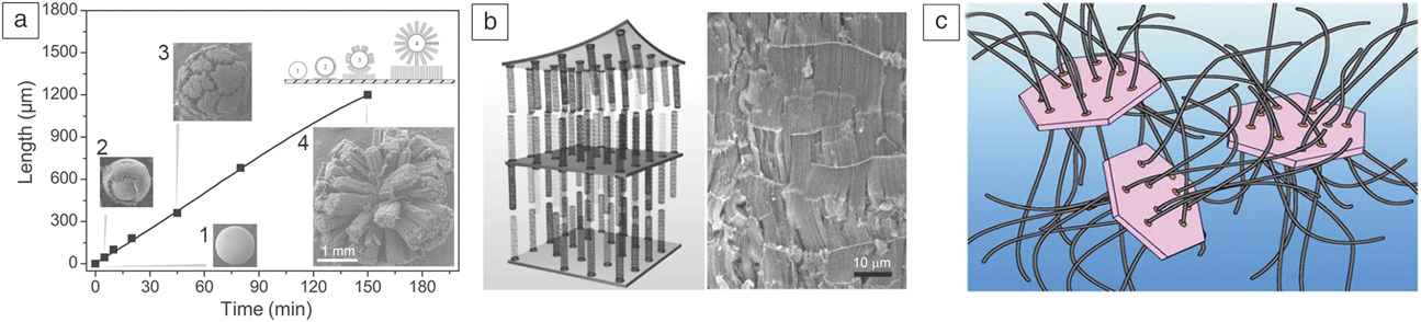
Some substrates such as alumina strongly interact with catalyst particles, allowing better metal dispersion and high-density SWCNT growth. Reference Hu, Kang, Zhao, Zhong, Zhang, Yang, Wang, Lin, Li and Zhang8 Although some substrates initially serve as a support for the as-grown CNTs, they may make substrate/CNT combination that can be utilized for subsequent applications. For example, Si/SiO2 substrates are used for ultralong CNT growth, and the combination is suitable for use as gate electrodes for the direct fabrication of transistors. Reference Zhu, Wei, Xie, Zhang, Bai, Wang, Zhang, Wang, Peng, Dai and Wei58 Wei’s group has developed a technique to make full use of natural support materials, not only as substrates, but also as functional hybrid materials. The initial strategy was related to the continuous production of aligned CNT arrays with millimeter-diameter spheres ( Figure 7a) as substrates. Reference Xiang, Luo, Qian, Wang, Wei and Li68 Layered vermiculite (a type of exfoliated clay compound) was further developed as a support (Figure 7b) for the production of CNT-based hybrid materials. Reference Zhang, Zhao, Liu, Cao, Qian, Lu and Wei69 The introduction of strong yet flexible CNTs produced a highly ductile and resilient composite with an energy absorption capacity nearly 10× that of the original compounds.
(a) Different morphologies and lengths of carbon nanotubes (CNTs) synthesized on spheres as a function of growth time. The length of CNTs linearly increases with time. Reprinted with permission from Reference Xiang, Luo, Qian, Wang, Wei and LiReference 68. © 2007 Wiley. (b) Scheme and scanning electron microscope images of the as-synthesized hybrid materials by intercalating a vertically aligned CNT film into layered vermiculite. Reprinted with permission from Reference Zhang, Zhao, Liu, Cao, Qian, Lu and WeiReference 69. © 2009 Wiley. (c) Schematic of the as-formed composite from the in situ growth of CNTs (gray) with layered double hydroxides (pink). Reprinted with permission from Reference Zhao, Zhang, Jia, Huang, Zhang and WeiReference 70. © 2010 Wiley.
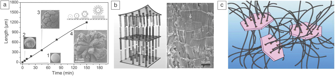
Carbon-based nanocomposites supported by a layered double hydroxide, schematically shown in Figure 7c, exhibited excellent electrical conductivity, mechanical strength, and chemical reactivity. Reference Zhao, Zhang, Jia, Huang, Zhang and Wei70 These layered inorganic supports play vital roles in stabilizing the catalyst particles and preventing sintering at high temperature, and are also promising for applications in new generation functional composites.
Summary
Catalysts play critical roles in the growth of SWCNTs. The composition, size, and structure of the catalysts highly affect the structure and quality of the SWCNTs produced. In SWCNT growth on substrates, catalysts for the chirality-selective growth of SWCNTs with a high density are greatly needed. Catalysts with a high melting point, unique atomic arrangements, and reasonable activity are the rational choice for such a purpose. In the bulk synthesis of SWCNTs, future attention may shift from high-yield growth to structure-controlled growth. More efforts are needed in catalyst design for the bulk preparation of SWCNTs with specified structures.

Xiulan Zhao is a doctoral candidate in the College of Chemistry and Molecular Engineering at Peking University, China. She earned her bachelor’s degree in chemistry from Shandong University, China, in 2013. Her research interests mainly focus on chirality-controlled synthesis of single-wall carbon nanotubes. Zhao can be reached by phone at +86-10-62754167 or by email at xiulanzhls@pku.edu.cn.
Shuchen Zhang is a postdoctoral researcher at Peking University, China. He received his BS degree from Shandong University, China, in 2012, and his PhD degree at Peking University. His research interests mainly focus on the preparation and properties of low-dimensional nanomaterials, including the structure-controlled growth of single-wall carbon nanotubes and their related applications. Zhang can be reached by phone at +86-10-62757157 or by email at zhangsc-cnc@pku.edu.cn.

Zhenxing Zhu is a doctoral candidate in the Department of Chemical Engineering at Tsinghua University, China. He obtained his bachelor’s degree in the Department of Chemical Engineering and Technology from Beijing University of Chemical Technology, China, in 2015. His research interests focus on the controlled synthesis, characterization, and growth mechanism of ultralong carbon nanotubes. Zhu can be reached by phone at +86 13301390972 or by email at zzx15@mails.tsinghua.edu.cn.
Jin Zhang was appointed as Changjiang Professor at Peking University, China, in 2013. He received his PhD degree from Lanzhou University, China, in 1997. After a postdoctoral fellowship at the University of Leeds, UK, he returned to Peking University, where he was appointed associate professor in 2000 and promoted to full professor in 2006. He is a Fellow of the Royal Society of Chemistry. His research focuses on the controlled synthesis and spectroscopic characterization of carbon nanomaterials. He has published more than 220 articles. Zhang can be reached by email at jinzhang@pku.edu.cn.

Fei Wei is a professor of chemical engineering at Tsinghua University, China. He obtained his PhD degree in chemical engineering from China University of Petroleum in 1990. After a postdoctoral fellowship at Tsinghua University, he was appointed associate professor in 1992 prior to being appointed professor in 1996. He has also been a visiting professor at The Ohio State University, University of Western Ontario, Canada, and Nagoya Institute of Science and Technology, Japan. His research interests include chemical-reaction engineering, multiphase flow, advanced materials, and sustainable energy. Wei can be reached by email at wf-dce@mail.tsinghua.edu.cn.

Yan Li has been full professor of chemistry at Peking University, China, since 2002. She received her PhD degree in inorganic chemistry from Peking University in 1993. From 1999 to 2001, she was a visiting associate professor at Duke University. She was designated a Chang Jiang Scholar by the Chinese Ministry of Education in 2014. She has held a distinguished visiting professorship at The University of Tokyo, Japan, since 2016. She is a Fellow of the Royal Society of Chemistry. She serves as associate editor for the journal ACS Nano and is on the advisory boards of the journals Materials Horizons and Journal of Materials Chemistry A. Her research focuses on the preparation, modification, characterization, and application of carbon nanotubes. Li can be reached by phone at +86-10-62756773 or by email at yanli@pku.edu.cn.