1. INTRODUCTION
An ultra-intense heavy ion beam is required for heavy-ion inertial fusion (HIF). The typical requirement for ion sources is several hundred mA of low-charge-state heavy ions (charge-to-mass ratio~100–200), such as 500 mA of Bi1+ to minimize the difficulty of a final focusing system caused by space charge repulsion force (Arnold and Meyer-ter-Vehn, Reference Arnold and Meyer-ter-Vehn1987; Hofmann, Reference Hofmann1998), while the existing operational heavy ion sources for particle accelerator facility provide beam current of up to 10 mA. A laser ion source (LIS) is one of promising candidates of such ion sources. In this source, laser-produced plasma containing heavy ions are produced from a solid target irradiated by a high-power pulsed laser. The charge state distribution mainly depends on laser power density on a target (Torrisi et al., Reference Torrisi, Gammino, Andò and Làska2002; Kondrashev et al., Reference Kondrashev, Kanesue, Okamura and Sakakibara2006). The main stream of LIS studies have been for highly charged heavy ion production (Collier et al., Reference Collier, Hall, Haseroth, Kugler, Kuttenberger, Langbein, Sharkov, Shumshurov and Masek1996; Dubenkov et al., Reference Dubenkov, Sharkov, Golubev, Shumshurov, Shamaev, Roudskoy, Streltsov, Satov, Makarov, Smakovsky, Hoffmann, Laux, Müller, Spädtke, Stöckl, Wolf and Jacoby1996; Kondrashev et al., Reference Kondrashev, Collier and Sherwood1996; Reference Kondrashev, Mescheryakov, Sharkov, Shumshurov, Khomenko, Makarov, Satov and Smakovskii2000; Haseroth et al., Reference Haseroth, Kugler, Langbein, Lisi, Lombardi, Magnusson, Pirkl, Schnuriger, Scrivens, Tambini, Tanke, Homenko, Makarov, Roerich, Stepanov, Satov, Kondrashev, Savin, Sharkov, Shumshurov, Krása, Láska, Pfeifer and Woryna1998; Sharkov et al., Reference Sharkov, Shumshurov, Roudskoy, Kilipio, Shaskov, Kiselev and Pashinin1999; Zhao et al., Reference Zhao, Zhang, Jin, Liu, Wang, Sun, Zhang and Zhao2016). By decreasing laser power density between 1E8 and 1E9 W/cm2, the charge state of ions is optimized for singly charged ions (Kanesue et al., Reference Kanesue, Tamura and Okamura2008). The laser-produced plasma expands three dimensionally toward the normal direction to the target surface without external forces. This expansion makes a pulse width of an ion beam from nanosecond to a desired width over microsecond scale. Ions are extracted after the expansion to avoid space charge repulsion caused by high-current ions. It is essential to investigate how to transport the expanding plasma to achieve a high-current beam before ions are extracted. A straight solenoid magnetic field was used to suppress transverse expansion (Takahashi et al., Reference Takahashi, Okamura, Sekine, Cushing and Jandovitz2013). A pulsed solenoid magnetic field was used to shape optimize the shape of the temporal profile of the plasma (Ikeda et al., Reference Ikeda, Takahashi, Okamura and Horioka2016). In this paper, the effect of a tapered magnetic field on the expanding laser-produced tantalum plasma was experimentally studied to concentrate laser-produced plasma on a beam axis. Experimental results were compared between the tapered magnet and a straight solenoid. Ion current was measured with laser shot on the magnet axis and 20 mm offset position. The magnetic field of interest was a wider opening on the target side and narrower opening on the extraction side. This configuration is to improve plasma density at extraction, typically limited to the aperture size of an ion extraction hole, to utilize more area of a laser spot on a target. To increase ion beam current, driver laser energy needs to be increased which requires increased laser spot size to keep the laser power density for singly charged ions. Other advantage of this configuration could be the improved tolerance to failures of lasers, by using multiple small lasers. The measured results with a tapered solenoid were compared with those with a straight solenoid magnet.
2. EXPERIMENTAL SETUP
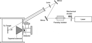
A basic wavelength of a Nd:YAG laser (THALES Laser SAGA230, λ = 1064 nm, pulse width = 6 ns) was used. The schematic of the experimental is shown in Figure 1. A mechanical shutter was placed in front of the laser to avoid unwanted laser emission. The laser light was transported in air by mirrors for high-power laser and focused by a plano-convex mirror (focal length = 4000 mm). The laser went into a vacuum chamber through a vacuum window toward a solid tantalum target. The thickness of the target was 1 mm. Incident angle of the laser was 30°. Laser energy and a spot size on the target were 720 mJ and 6 mm in diameter, respectively. This corresponds to the power density of
 $4 \times 10^8{\kern 1pt} {\rm W/c}{\rm m}^{\rm 2}$
. Pressure of the vacuum chamber was kept below
 $7 \times 10^{ - 4}{\kern 1pt} {\rm Pa}$
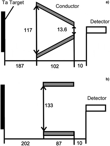
. Ion signal in a laser-produced plasma was measured by an ion probe biased at −200 V. The probe was placed in a grounded metal enclosure, which had a collimator of 1 mm in diameter at the entrance at 10 mm far from the probe. A grounded mesh was placed between the collimator and the probe at 5 mm from the probe. The distance from the target to the ion probe was kept at 300 mm throughout experiments. Two types of electromagnetic magnets were fabricated to investigate the effect of a tapered magnetic field. One was a tapered coil, and the other was a straight solenoid. Dimensions of the coils are shown in Figure 2. The coil of the tapered solenoid had 102 mm of length. Inner diameter on the target side, that on the other side, and total turns of conductor were 13.6 mm, 117 mm, and 209, respectively. The coil length, inner diameter, and total turns of conductor of the straight solenoid were 87 mm, 133 mm, and 81, respectively. The distance between the target and the edge of the coil was 187 and 202 mm for the straight solenoid and the tapered solenoid, respectively. A laser path was fixed and the target, magnet, and ion probe were shifted to shift the laser spot by 20 mm.
Experimental setup

Dimension of (a) a tapered solenoid and (b) a straight solenoid

3. RESULTS
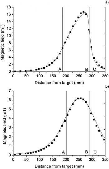
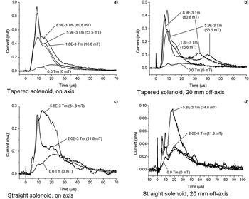
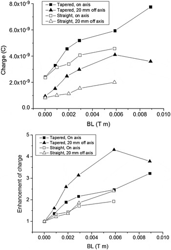
The axial magnetic field on the axis of each solenoid was measured before installing in the vacuum chamber. The measured magnetic field and the field calculated based on the coil specification, which are shown in Figure 3, showed good agreement. In this paper, we define an integral of an axial magnetic field along the axis as a BL integral. The measured ion signals produced from the solenoid axis and from 20 mm off-axis position are shown in Figure 4. The shown ion signals are ten shots averaged signals. BL integrals up to 8.9 × 10⁻³ T m for the tapered solenoid and 5.9 × 10⁻³ T m for the straight solenoid were used. Without a magnetic field, no major difference of detected signals between two types of the magnets was observed. Total charge measured in the on-axis plasma generation experiment was larger than that in the 20 mm off-axis experiment. This is because laser-produced plasma expands normal direction to a target surface, and plasma density on the axis of laser spot is dense. A fast peak was observed around 9.2 µs in addition to a main tantalum peak at 22 µs. The fast peak may be a peak of light ions such as C, N, and O generated from the surface contamination of the target. The current enhancement was stronger for the fast peak than the main peak. With the tapered solenoid magnet, ion current enhancement depended on velocity of ions and a radial position of plasma generation, while the dependency of a radial position is small with the straight solenoid. Faster ions were more affected by a magnetic field for both magnets, while obvious ion enhancement of slow ions generated from 20 mm off-axis position was observed only with the tapered solenoid. Total charge measured by the ion probe was compared to evaluate the performance of each magnet. To minimize the effect of possible light ions in the fast peak, ions measured after 12 µs were integrated. Figure 5 shows the total charge as a function of a BL integral and charge enhancement factor compared with the charge without magnetic field. For all range of BL integrals in the experiment, measured charge with the tapered solenoid was laser than that with the straight solenoid. The enhancement factor curves had similar tendencies for all experiments up to a BL integral of 5.9 × 10⁻³ T m. For laser-produced plasma generated on the magnet axis, total charge measured with the tapered solenoid was 1.3 times larger than that with the straight solenoid at 5.9 × 10⁻³ T m. The measured charge of the ions produced from 20 mm off-axis position started to decrease at 8.9 × 10⁻³ T m with the tapered solenoid. The results below BL integral of 5.9 × 10⁻³ T m were considered to evaluate the effect of the tapered solenoid on the plasma generated at off-axis position. The tapered solenoid showed higher efficiency to collect plasma generated at 20 mm off-axis position on the center of magnet at the exit. At 5.9 × 10⁻³ T m, The charge measured with the tapered magnet was 69% generated from the magnet axis, while the percentage was only 44% in case of the straight solenoid.
Measured axial magnetic field (dot) and that of calculated based on the coil specification (line) for (a) the tapered solenoid (7.0 A per conductor) and for (b) the straight solenoid (10.0 A per conductor). BL integrals for (a) and (b) were 1.8 × 10⁻³and 1.0 × 10⁻³ T m, respectively. Position A and B indicates the edge of a magnet coil, and C is the edge of a detector.

Measured ion signal with a tapered solenoid (a,b) and a straight solenoid (c,d). Note that BL integrals up to 8.9 × 10⁻³ T m for the tapered solenoid and 5.9 × 10⁻³ T m for the straight solenoid were used, but not all measured signals are shown here. Plasma was generated on axis in (a,c), and at 20 mm off-axis in (b,d).

Charge (top) and charge enhancement factor compared with the charge without magnetic field (bottom) as a function of a BL integral.

4. DISCUSSION
The shape of a magnet core (tapered or straight) did not affect the measured ion signal without magnetic field within the physical configuration used. We experimentally confirmed that the tapered solenoid concentrates ions generated from 20 mm off-axis position onto the axis of the magnet at the exit. Because magnetic field outside of a coil rapidly decreases, higher current enhancement is expected as decreasing the distance between a target and a magnet coil. Based on the experiment results, the performance of a LIS for high-current and low-charged ions can be estimated. For example, for an ion source for HIF, the required beam current and pulse width for an ion source are estimated as 500 mA and 20 µs, respectively, assuming 100 beam lines to achieve total beam charge of about 1 mC (Kwan et al., Reference Kwan, Ahle, Beck, Bieniosek, Faltens, Grote, Halaxa, Henestroza, Herrmannsfeldt, Karpenko and Sangster2001).
We use a laser spot size of 40 mm in diameter for the estimation to use the measured data. To keep the laser power density used in the experiment, a 32 J/6 ns laser is required. We assumed that the number of ions is proportional to laser energy. For a simple estimation, an average of ion charge generated between on axis and 20 mm off-axis was used as an available charge generated from laser spot of 6 mm in diameter. Under these assumptions, total ion charge at 10 mm from the edge of a tapered solenoid is 2.2 × 10⁻⁷ C in 1 mm in diameter in case of a BL integral of 5.9 × 10⁻³ T m. High-current ion beam acceleration can be achieved by extracting ions in a radio frequency quadrupole linear accelerator (Kashiwagi et al., Reference Kashiwagi, Fukuda, Okamura, Jameson, Hattori, Hayashizaki, Sakakibara, Takano, Yamamoto, Iwata and Fujimoto2006; Ishibashi et al., Reference Ishibashi, Hayashizaki and Hattori2011; Sha et al., Reference Sha, Zhao, Guo, Zhang, Fang, Guo, Zhang, Lu, Cao, Ma, Lin, Li, Ma, Yang, Wang, Wu, Li, Feng, Zhao, Zhu, Sun, Zhang, Chen and Xie2012; Kanesue et al., Reference Kanesue, Fuwa, Kondo and Okamura2014). Assuming a typical ion extraction aperture of 6 mm, ion charge at the extraction is estimated as 8.0 × 10⁻⁶ C per pulse. Based on Figure 4, the pulse width of ion beam is about 10 µs. The pulse width can be extended by increasing the distance between a laser irradiation target and an extraction aperture. The shape of a tapered solenoid and magnetic field strength should be investigated. Other advantage of increased laser spot size using a tapered magnetic field is an option to use multiple small lasers instead of a large-scale laser. In this case, the reliability of a LIS is greatly increased by keeping several lasers as backup. This is critical for continuous operation.
5. CONCLUSION
We demonstrated that a tapered solenoid magnet is more effective to concentrate laser-produced plasma toward the magnet axis than that of a straight solenoid. The effect was confirmed at the plasma generated from 20 mm off-axis position on the axis of the magnet. Based on the experimental results, a LIS for high current and low-charged ion beam was estimated. The estimated performance was close to the requirement of HIF in terms of ion charge and pulse width. Increased laser spot size with a tapered solenoid magnet can increase the reliability of a high-current and low-charged LIS using multiple lasers.
ACKNOWLEDGMENTS
This work was supported by the U.S. Department of Energy and National Aeronautics and Space Administration.