





1. Introduction
People aspire to live on the Moon. To achieve this, we need to develop safe landing mechanisms. Ensuring sustainable and safe landings provides infinite opportunities for further space exploration. However, attaining a stable landing on a planetary surface stands as a paramount concern in the realm of space immigration. Interaction between the lander's exhaust and planetary surface is a key component of this problem. The chosen landing site usually consists of a flat and crater-free terrain (Toigo & Richardson Reference Toigo and Richardson2003). Nonetheless, the plume ejected from a descending spacecraft has the potential to induce cratering and splashing, leading to a potentially unstable landing scenario. It is necessary to conduct a thorough assessment of the cratering and regolith grain splashing induced by an air jet on a planetary surface. To explore the inherent nature of this type of phenomenon, it is essential to uncover a universal scaling framework for the granular cratering caused by the impact of air jets. However, accurately replicating a fully realistic landing scenario is difficult. Consequently, researchers usually perform small-scale laboratory experiments to explore scaling relationships. This study is dedicated to investigating granular cratering resulting from air-jet impact by a small-scale experiment. Through systematic analysis of laboratory-scale experiments, we derive a universal scaling law governing the crater morphology. The obtained scaling includes newly defined scaling parameters and offers a novel direction for research on the interaction between a fluid and granular matter. In addition, this scaling would allow us to anticipate the potential landing scenarios on various planetary surfaces in future space missions.
Crater formation due to an impact is an extremely complex phenomenon (Holsapple & Schmidt Reference Holsapple and Schmidt1982; Croft Reference Croft1985; Uehara et al. Reference Uehara, Ambroso, Ojha and Durian2003; Lohse et al. Reference Lohse, Bergmann, Mikkelsen, Zeilstra, Van Der Meer, Versluis, Van Der Weele, van der Hoef and Kuipers2004; Katsuragi Reference Katsuragi2016; Prieur et al. Reference Prieur, Rolf, Luther, Wünnemann, Xiao and Werner2017; Van Der Meer Reference Van Der Meer2017; Yamamoto et al. Reference Yamamoto, Hasegawa, Suzuki and Matsunaga2017; Allibert et al. Reference Allibert, Landeau, R”ohlen, Maller, Nakajima and Wünnemann2023). Jet impact crater formation further involves the interaction between a continuously impinging pressurized fluid and a granular surface, which results in a bowl-shaped depression. The crater shape varies with the properties of the target material and the impinging fluid. Landing rockets on planetary surfaces and erosion near hydraulic structures are important examples relating to jet-impact-induced cratering (Rajaratnam & Beltaos Reference Rajaratnam and Beltaos1977; Lane et al. Reference Lane, Metzger, Clements and Immer2010; Badr, Gauthier & Gondret Reference Badr, Gauthier and Gondret2014a,Reference Badr, Gauthier and Gondretb; LaMarche & Curtis Reference LaMarche and Curtis2015; Gorman et al. Reference Gorman, Rubio, Diaz-Lopez, Chambers, Korzun, Rabinovitch and Ni2023; Metzger Reference Metzger2024a). Here, we focus on the cratering phenomena that may cause problems during the landing and re-launching of rockets. Particularly, hardware damage to the rocket body or its sensors can be caused by large amounts of dust kicked up by exhaust plumes. Understanding this type of plume–surface interaction (PSI) process is one of the most important issues in the space engineering field (Donohue, Metzger & Immer Reference Donohue, Metzger and Immer2021; Baba et al. Reference Baba, Okita, Watanabe, Maru, Sawai, Mori and Fujita2023; Gorman et al. Reference Gorman, Rubio, Diaz-Lopez, Chambers, Korzun, Rabinovitch and Ni2023; Bajpai, Bhateja & Kumar Reference Bajpai, Bhateja and Kumar2024). Indeed, dust ejecting up onto the sensors was one of the many reasons for recent landing failures on the lunar surface (Witze Reference Witze2023; Metzger Reference Metzger2024b).
The granular crater formation caused by the fluid impact has been studied by many researchers (Rajaratnam & Beltaos Reference Rajaratnam and Beltaos1977; Metzger et al. Reference Metzger, Latta III, Schuler and Immer2009; Lane et al. Reference Lane, Metzger, Clements and Immer2010; Metzger, Smith & Lane Reference Metzger, Smith and Lane2011; Zhao, Zhao & Liu Reference Zhao, Zhao and Liu2013; Badr et al. Reference Badr, Gauthier and Gondret2014a,Reference Badr, Gauthier and Gondretb; Clark & Behringer Reference Clark and Behringer2014; LaMarche & Curtis Reference LaMarche and Curtis2015; Badr, Gauthier & Gondret Reference Badr, Gauthier and Gondret2016; Guleria & Patil Reference Guleria and Patil2020; Donohue et al. Reference Donohue, Metzger and Immer2021; Gong et al. Reference Gong, Azadi, Gans, Gondret and Sauret2021; Benseghier et al. Reference Benseghier, Luu, Cuéllar, Bonelli and Philippe2023). Various mechanisms reported for crater formation include viscous erosion (VE), diffused gas eruption (DGE), bearing capacity failure (BCF) and diffusion-driven shearing (Metzger et al. Reference Metzger, Latta III, Schuler and Immer2009; Lane et al. Reference Lane, Metzger, Clements and Immer2010; Metzger et al. Reference Metzger, Smith and Lane2011; Kuang et al. Reference Kuang, LaMarche, Curtis and Yu2013). The VE is the most common and most investigated (Zhao et al. Reference Zhao, Zhao and Liu2013; Badr et al. Reference Badr, Gauthier and Gondret2014a,Reference Badr, Gauthier and Gondretb; Clark & Behringer Reference Clark and Behringer2014; Badr et al. Reference Badr, Gauthier and Gondret2016). The cratering process is controlled by the conditions of the impinging jet and erodible granular bed. During crater erosion, both the crater depth and diameter grow with time and approach the asymptotic values (Zhao et al. Reference Zhao, Zhao and Liu2013; Badr et al. Reference Badr, Gauthier and Gondret2014a; Donohue et al. Reference Donohue, Metzger and Immer2021; Gorman et al. Reference Gorman, Rubio, Diaz-Lopez, Chambers, Korzun, Rabinovitch and Ni2023). The scaling laws for crater morphology were studied based on the Froude, Shields and erosion numbers (Clark & Behringer Reference Clark and Behringer2014; Guleria & Patil Reference Guleria and Patil2020; Gong et al. Reference Gong, Azadi, Gans, Gondret and Sauret2021). However, these scaling relationships are applicable only to each specific condition. There is a lack of consistency across various experiments, hindering the establishment of a unified understanding among these previous studies. The pursuit of universal scaling relations for granular cratering induced by air-jet impact is a critical issue and intersects both fundamental granular physics and space engineering. In this paper, we propose a unified scaling relation for jet-induced granular cratering, to better understand the PSI process. Particularly, new dimensionless parameters are introduced to aim at providing universal explanations for the systematic experimental results. Besides, we report a novel sub-surface cratering phenomenon as well.
The rest of the paper is organized as follows: in the next section, the experimental set-up, materials and procedures are introduced. In § 3, we define the various kinds of craters formed and discuss a scaling analysis for crater dimensions using well-known non-dimensional numbers. Then, we propose a unified scaling law for the crater's aspect ratio that characterizes the crater morphology. In § 4, we discuss the advantages of the improved scaling relation, further improvements that can be done and a novel drop-shaped crater that we encounter. Finally, we conclude in § 5.
2. Experiments
We systematically perform laboratory-scale experiments to form air-jet-induced craters. Figure 1 shows the schematic of the experimental set-up. We perform experiments in a three-dimensional (3-D) half-space set-up to capture crater images. The rectangular container of inner dimensions  $240 \times 200 \times 70\ {\rm mm}^3$ contains the granular material, which serves as a planetary surface simulant. The compressed air jet, mimicking the nozzle exhaust, is directed vertically downwards along the acrylic wall, keeping a minimum distance of approximately
 $1\ {{\rm mm}}$ between the nozzle and the acrylic wall while minimizing the influence of the wall on the central jet velocity (Rajaratnam & Beltaos Reference Rajaratnam and Beltaos1977; Schlichting & Gersten Reference Schlichting and Gersten1979; LaMarche & Curtis Reference LaMarche and Curtis2015; Guleria & Patil Reference Guleria and Patil2020). The formation of boundary layer along the wall is discussed separately in Appendix A.1. The pressure-controlled air jet of
 $0.01$–
 $0.3$ MPa pressure range comes out through a nozzle. We vary the nozzle diameter,
 $d_n$, to control the impinging air-jet velocity,
 $v_n$. The distance between the granular surface and the nozzle tip,
 $h_n$, is also varied. The variation in
 $h_n$ captures the dynamic advancement of the rocket towards the landing surface. As shown in figure 1(b), the air jet is directed onto a granular bed of grain size
 $d_g$ and true density
 $\rho _g$. Upon jet–surface interaction, figure 1(c) captures the formation of the crater of width
 $D_c$ and depth
 $H_c$ from the initial surface level (dotted line). In this study, we focus on the steady crater shapes, i.e. constant
 $D_c$ and
 $H_c$ conditions. The steady crater shape is immediately developed within a few seconds. Due to its greater tendency to erode, finer and lighter granular material needs more time to reach a steady state than the coarser and heavier grains.
(a) The schematic of the experimental set-up for air-jet impact experiments in a three-dimensional half-space set-up, (b) a magnified view of the cratering process, (c) an example image of a crater and (d) a sketch of the impinging air-jet configuration.

Table 1 shows the properties of the grains used in the experiments. The initial packing fraction and angle of repose are denoted by  $\varphi _i$ and
 $\theta$, respectively. The BZ series and SUS304 represent spherical glass beads and cylindrical steel-cut-wire beads, respectively, whereas the sand is the irregular-shaped Toyoura sand. The initial volume fraction, as mentioned in table 1, would remain approximately the same as the uncertainty of the mass in the container is observed to be less than
 $1\,\%$ during random sampling measurements.
Properties of granular materials.

The experiments are conducted in the following sequence. We first fill the container by pouring the grains and precisely maintaining the flat surface. The nozzle tip of  $d_n$ is placed at
 $h_n$. Then, the cratering induced by the air-jet impact is recorded by the camera (STC-MCCM401U3V) that captures side-view images at
 $200\ \mathrm {fps}$ with a spatial resolution of
 $0.058\ {\rm mm}\ {\rm pixel}^{-1}$ and
 $2048 \times 2048$ image size. As shown in figure 1(c),
 $D_c$ is the width of the crater cavity at the initial horizontal surface level (dotted line) and
 $H_c$ is the depth of the cavity measured vertically down from the initial surface level. During every experiment, an air jet impinges the granular bed for
 $10\ {\rm s}$. See tables 3 and 4 in Appendix A.2 for more details of the experimental conditions. We consider the average of five measurements taken for each experimental condition. A total of more than 700 experiments are carried out. Table 2 shows the range of control parameters in the experiments. Further details regarding experiments can be found in Appendix A.2.
Operational range of control parameters.

3. Results
Figure 2(a) shows a phase diagram of various crater types for varying  $h_n$ and
 $M_n$, where
 $M_n = v_n/C$ is the dimensionless air-jet velocity at the nozzle and
 $C=343\ {\rm m}\ {\rm s}^{-1}$ is the speed of sound in air. As shown in figure 2(b–g), we observe six types of craters. Five of these, figure 2(b–f), are already documented in the literature (Lane et al. Reference Lane, Metzger, Clements and Immer2010; Clark & Behringer Reference Clark and Behringer2014; Guleria & Patil Reference Guleria and Patil2020). We reproduce these results over a broader range of parameters, i.e. by exploring all the controlling variables mentioned in table 2 that span a considerably wide range of at least over a decade. As seen in figure 2(a), the ‘parabola’ craters (
 $\boldsymbol {\circ }$, blue) and the parabola with ‘intermediate’ region craters (
 $\unicode{x2B20}$, green) are observed most frequently within the current parametric range. However, ‘V-shaped’ craters (
 $\nabla$, cyan) are formed more frequently for finer grains (see figures 10 and 11 in Appendix B for all phase diagrams and the congregated phase diagram, respectively). The ‘saucer’-type wide and shallow craters (
 $\boldsymbol {\diamondsuit }$, red) and ‘U-shaped’ narrow and deep craters (
 $\boldsymbol {\square }$, orange) are formed at high and low
 $h_n$ ranges, respectively. Moreover, we find a novel crater shape (figure 2g), the ‘drop-shaped’ cavity, beneath the granular surface (
 $\boldsymbol {\triangle }$, magenta), which has not been reported in the literature yet. While we also observe ‘truncated-shape’ craters due to the size limit of the experimental set-up (see figure 12a,b in Appendix C), we exclude these truncated craters from the following analysis because the crater's depth
 $H_c$ cannot be measured for them. The details and movies related to various types of crater formation can be found in Appendix D and the supplementary material (SM) available at https://doi.org/10.1017/jfm.2024.906.
(a) Phase diagram shows craters formed when a pressurized air jet is directed through the nozzle ( $d_n = 3.6\ {\rm mm}$) onto SUS304 grains. Various shapes of craters observed over a range of experimental conditions are: (b) saucer, (c) parabola, (d) parabola with the intermediate region, (e) U-, (f) V- and (g) drop-shaped craters. The
 $\times$, grey symbols correspond to no-crater formation. In the phase diagram,
 $h_n$ represents the distance from the nozzle tip to the granular surface, and
 $M_n = v_n/C$ is the dimensionless air-jet velocity at the nozzle, where
 $C=343\ {\rm m}\ {\rm s}^{-1}$ is the speed of sound in air.

Now, considering the varied and complex range of craters, we analyse the crater morphology and its governing parameters in detail. To obtain the scaling relation, we introduce two dimensionless numbers,  $G_n = d_n/h_n$ and
 $r=\rho _g/\rho _a$, where
 $\rho _a=1.2\ {\rm kg}\ {\rm m}^{-3}$ is the air density. The parameter
 $G_n$ relates to the velocity profile of the turbulent jet, as shown in figure 1(d). The velocity of the air jet would reduce to
 $v_s = (5/2)M_n \, G_n \, C$ (for turbulent jets, the universal angle of a diverging cone is approximately
 $24\,^{\circ }$. Thus, the initial jet radius and the downstream distance
 $z$ from the nozzle exit are related by a constant
 $\tan (12^{\circ })\sim 1/5$. The distance
 $z$ is counted not from the nozzle exit but from a distance
 $5d_n/2$ into the nozzle. This point of origin is called the virtual source (Cushman-Roisin Reference Cushman-Roisin2014). We use this axisymmetric model for our 3-D half-space experimental set-up as a first step to investigate the scaling relation) at the surface of the granular bed (Cushman-Roisin Reference Cushman-Roisin2014). By using
 $r$, a dimensionless number proportional to the dynamic pressure of the air jet,
 $\rho _a v_n^2$, can be expressed by
 $(M_n/r^{1/2})^2$. From the measured data, we find that
 $D_c$ and
 $H_c$ can be scaled as
 $D_c \sim G_n^{-1}$ and
 $H_c \sim M_n/r^{1/2}$. Figures 3(a) and 3(b) shows the relations
 $D_c$ vs
 $G_n$ and
 $H_c$ vs
 $M_n/r^{1/2}$, respectively. Namely,
 $D_c$ is mainly governed by the air-jet geometry and
 $H_c$ is principally determined by the dynamic pressure of the impinging air jet. From these relations, we investigate a scaling law for the crater's aspect ratio
 $R_c=D_c/H_c$. For the safe rocket landing situation, large-
 $R_c$ (shallow and flat) cratering causes the ejecta to flow radially outward and is thus preferred over vertically ejected grains that might cause the malfunction of the lander as in the case of deep crater formation. Therefore,
 $R_c$ is the most important parameter characterizing this type of cratering.
The scaling relations among  $D_c$,
 $H_c$,
 $G_n = d_n/h_n$,
 $M_n$ and
 $r=\rho _g/\rho _a$ are presented. Panels (a,b) suggest the scaling relations as
 $D_c \sim G_n^{-1}$ and
 $H_c \sim (M_n/r^{1/2})^1$, respectively. The inset of (a) shows a plot of the same data on a log–log scale. The data shown in (a,b) originate from the experiments performed with BZ1 grains using
 $d_n = 3.6 \ \mathrm {mm}$.

The roles of conventional dimensionless numbers have been thoroughly investigated by researchers (Badr et al. Reference Badr, Gauthier and Gondret2016; Guleria & Patil Reference Guleria and Patil2020; Gong et al. Reference Gong, Azadi, Gans, Gondret and Sauret2021). They used the Froude number  $Fr = {v_n}/\sqrt {g d_g}$, the Shields number
 $Sh = Fr \, \sqrt {{\rho _a}/{(\rho _g - \rho _a)}}$ and the Reynolds number
 $Re = \rho _a v_n d_n/ \mu _a$, where
 $g$ is the gravitational acceleration and
 $\mu _a$ is the viscosity of air. For our case, we observe that the
 $Re$,
 $Fr$ and
 $Sh$ are not sufficient to scale
 $R_c$ since
 $h_n$ is not included in these dimensionless numbers; as shown in figures 4(a)–4(c), respectively. In addition, while studying the temporal evolution of a crater formed by rocket exhaust, Rajaratnam et al. introduced an erosion number
 $E_c =Sh~G_n$, which incorporates various relevant parameters (Rajaratnam & Beltaos Reference Rajaratnam and Beltaos1977; Donohue et al. Reference Donohue, Metzger and Immer2021). However, during an experimental investigation of the growth rate of the crater, Donohue et al. indicated that
 $E_c$ may not accurately characterize the crater formation (Donohue et al. Reference Donohue, Metzger and Immer2021). Remarkably, focusing on the crater morphology observed in this paper, the erosion number,
 $E_c$, indeed shows promising results but only when one kind of granular surface is considered (see figure 4d). Yet, figure 5 suggests that the data scatter for other experimental parameters.
Crater's aspect ratio,  $R_c$, vs (a)
 $Re$, (b)
 $Fr$, (c)
 $Sh$ and (d)
 $E_c$. Experiments are performed for BZ1 and
 $d_n = 3.6 \ \mathrm {mm}$.

The aspect ratio,  $R_c$, is plotted as a function of
 $E_c$. A certain degree of collapse can be observed, but the quality of the data collapse is not very good. Inset shows a plot of the same data on a log–log scale. The shape of symbols represents various
 $h_n$ values.

Now, we consider a more appropriate choice for a scaling law. From figures 3(a) and 3(b),  $D_c\sim G_n^{-1}$ and
 $H_c\sim M_n/r^{1/2}$ results in the combined scaling
 $R_c \sim (M_n \, G_n/r^{1/2})^{-1}$. Figure 6 shows the scaling
 $R_c \sim (M_n \, G_n /r^{1/2})^{-1}$. One can confirm the reasonable data collapse, particularly in the small
 $M_n \, G_n /r^{1/2}$ regime. The obtained scaling is almost consistent with the numerical simulation of air-jet impact onto a granular bed (Kuang et al. Reference Kuang, LaMarche, Curtis and Yu2013); see the filled
 $\unicode{x2B20}$, black in figure 6. Although this scaling reasonably collapses the experimental data, we realize the data for small
 $h_n$ (filled circular symbols) systematically deviate from the scaling.
The crater aspect ratio  $R_c$ of all experiments is plotted as a function of
 $M_n \, G_n /r^{1/2}$. Inset shows a plot of the same data on a log–log scale. The colour indicates the target material and
 $d_n$ conditions. The shapes of the symbols represent
 $h_n$ values. The filled circular symbols represent data for
 $h_n = 10 \ \mathrm {mm}$ for each corresponding colour condition.

To obtain a better scaling,  $R_c$ at the smallest
 $h_n(=10\ {\rm mm})$ is further analysed. We find the average of
 $R_c$ at
 $h_n=10\ {\rm mm}$,
 $\bar {R}^{h10}_c$ is scaled as
 $\bar {R}^{h10}_c \sim (r \delta )^{1/2}$, where
 $\delta =d_n/d_g$. Figure 7 clearly indicates the scaling
 $\bar {R}_c^{h10}\sim (r \delta )^{1/2}$ except for the largest grains BZ2 (
 $d_g=2\ {\rm mm}$). This scaling in the small
 $h_n$ regime results from switching of the relevant length scale from
 $h_n$ to
 $d_g$, as
 $h_n$ decreases. Thus, as the lander approaches the surface, the grain size becomes more significant compared with the nozzle height.
The average of aspect ratio  $R_c$ at
 $h_n = 10 \ \mathrm {mm}$;
 $\bar {R}^{h10}_c$, is plotted as a function of
 $(r\delta )^{1/2}$.

The form of scaling  $R_c=(r\delta )^{1/2} = (\rho _g d_n/(\rho _a d_g))^{1/2}$ is slightly puzzling. The density and length scale of the air jet and grains are not naturally linked to the crater's aspect ratio. This counter-intuitive correlation could originate from the deformability of the impactor (Katsuragi Reference Katsuragi2010), as well as the mixing of the granular substrate and the impactor (Nefzaoui & Skurtys Reference Nefzaoui and Skurtys2012; Zhao et al. Reference Zhao, Zhang, Tjugito and Cheng2015a; Zhao, de Jong & van der Meer Reference Zhao, de Jong and van der Meer2015b, Reference Zhao, de Jong and van der Meer2017; Van Der Meer Reference Van Der Meer2017). For example, cratering by a droplet impact on a permeable substrate also shows a similar inverse tendency (Katsuragi Reference Katsuragi2010). Specifically, a similar density dependence of the crater radius formed by droplet impact was reported. Namely, the larger crater diameter was observed for larger
 $\rho _g$. Recently, Zhao et al. performed experiments to study droplet impact on sand (Zhao et al. Reference Zhao, de Jong and van der Meer2015b, Reference Zhao, de Jong and van der Meer2017). It was observed that liquid–grain mixing suppresses droplet spreading and splashing. During the experiments, the packing density of the granular target, grain size, wettability conditions and the impact velocity are varied. It was found that, by increasing the grain size and the wettability conditions, the maximum droplet spreading undergoes a transition from a capillary regime towards a viscous regime. This complex interaction between droplet intruder and granular target creates various crater morphologies (Zhao et al. Reference Zhao, de Jong and van der Meer2017). These tendencies could be typical difficulties in soft-impact studies. In our case, high-velocity air can penetrate the shallow layers of the permeable granular substrate with more ease than can a water droplet. The low dynamic viscosity of air, compared with water or other liquids, allows for easier permeation of the granular bed, viewed as a porous medium. This prolonged presence of jet air within the subsurface layers while the crater is being formed may alter the local properties of the granular target during crater formation. Thus, the empirical scaling obtained here can be used to formalize the scaling better than the previously proposed ones.
Finally, we derive the unified scaling law based on the above-mentioned scaling results. The combined scaling function is written as
 \begin{equation} \frac{R_c}{(r \delta)^{1/2}} = f\left( M_n G_n \delta^{1/2} \right), \end{equation}
where the function  $f(x)$ satisfies
 $f(x) \sim x^{-1}$ in the small
 $x$ regime and
 $f(x)\simeq$ const. in the large
 $x$ regime. This functional form indeed recovers
 $R_c \sim (M_nG_n/r^{1/2})^{-1}$ at large
 $h_n$ and
 $R_c \sim (r \delta )^{1/2}$ at small
 $h_n$. In figure 8, the scaling cross-over point is
 $M_n G_n \delta ^{1/2} \simeq 10^{-1}$. Therefore, the cross-over
 $h_n$ can be computed as
 $h_c \simeq 10M_n \delta ^{1/2}d_n$. In such a complex PSI process, capturing a shift in the relevant length scale and its cross-over point is an important takeaway of this paper.
The scaling relation of (3.1),  $R_c / (r \delta )^{1/2}=f(M_n G_n \delta ^{1/2})$, is presented for all experimental data. Except for the largest grain data (BZ2,
 $d_g=2\ {\rm mm}$, filled symbols in the plot), all the data obey the scaling. The shape of the symbols represents various
 $h_n$ values.

When the grain size is the largest (BZ2 grains), however, the data cannot be scaled (filled symbols in figure 8). This indicates that the cratering dynamics is completely different when  $d_g \sim d_n$. Namely,
 $d_n$ must be sufficiently greater than
 $d_g$ to safely apply the obtained scaling. This result is informative to provide the lower limit of the nozzle size in the lander design.
4. Discussion
The unified scaling law presented in figure 8 (and (3.1)) is superior to the previously reported scaling laws that are based on conventional dimensionless numbers.
Moreover, from the fluid mechanics perspective, these scaling relations can be further investigated to study the grain motion and convection currents during the temporal evolution of the different types of craters. In addition, our result shows the cross-over of scaling laws, which may be of interest to researchers studying soft matter physics (Maruoka Reference Maruoka2023). By using the obtained scaling,  $R_c \sim (M_n G_n/r^{1/2})^{-1}$, we can estimate
 $R_c$ mainly from the jet conditions in the large
 $h_n$ regime. We do not need detailed information about the landing surface. Having a simple scaling parameter mainly consisting of jet conditions is advantageous to reducing uncertainty in space missions. Within the approachable distance, we should use the relation
 $R_c \sim (r \delta )^{1/2}$, i.e. grain size information is necessary in the small
 $h_n$ regime.
The 3-D half-space experimental set-up has limitations, such as the presence of an acrylic wall that forms a boundary layer affecting the jet's velocity structure. Thus, this set-up might break the axisymmetric assumption for the jet. This may affect the surface erosion and the crater dimensions. We believe that by addressing such experimental limitations, the current scaling relations (in figure 8) may further be improved by reducing data scatter around the scaling. To consider a realistic rocket landing application, we have to estimate the ejection speed, angle, etc. Besides, the effects of gravity and ambient air must be evaluated. In this experiment, dimensionless numbers including the gravity effect ( $Fr$,
 $Sh$, and
 $E_c$) do not work well to collapse the data (figures 4 and 5). As demonstrated in Baba et al. (Reference Baba, Okita, Watanabe, Maru, Sawai, Mori and Fujita2023), however, air-jet cratering and the resultant ejection process are significantly affected by the gravity condition. Modification of the obtained scaling and the precise measurement of ejector behaviour are the important next steps to consider in an actual landing application. The scaling function developed in this study provides a starting point for further investigations.
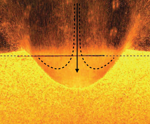
As mentioned earlier, we observe a novel drop-shaped sub-surface cratering phenomenon on a few occasions, especially when the nozzle tip is very close to a granular surface (see  $\boldsymbol {\triangle } $, magenta in figure 2a) consisting of coarser/denser grains. In low
 $h_n$ cases, the turbulent jet impinges on the granular surface at high
 $v_s$. In the case of coarser grains, the larger pores between the grains allow easier penetration of the high-velocity turbulent air jet. Then, the jet penetrates through the surface and expands beneath. In contrast, a granular surface made of finer grains is easy to erode. In such a case, the air escapes out while eroding the surface and a drop-shaped cavity cannot be formed. The denser and coarser SUS304 grains are difficult to displace, but allow the trapped air to deform the sub-surface material (see figure 12c in Appendix C).
The drop-shaped crater can be attributed to the BCF or DGE mechanisms (Alexander, Roberds & Scott Reference Alexander, Roberds and Scott1966; Scott & Ko Reference Scott and Ko1968; Metzger et al. Reference Metzger, Latta III, Schuler and Immer2009). However, BCF forms craters with long and narrow cylindrical shapes when a pressurized rocket exhaust pushes the soil down into a depression. In contrast, we observed convection currents within the drop-shaped craters with narrow  $D_c$ and minor displacement of the grains around the drop cavity as air diffuses into the material. Thus, we believe this phenomenon can be related to the DGE (Scott & Ko Reference Scott and Ko1968; Metzger et al. Reference Metzger, Latta III, Schuler and Immer2009), which usually causes an annular-ring eruption around the jet. However, we have not seen such eruptions in our small-scale experiments. Further study is necessary to reveal the physical mechanism governing the drop-shaped crater. In addition, this intriguing phenomenon is particularly significant to understanding the rocket launch scenarios from planetary surfaces, where sudden high-speed exhaust thrust needs to be applied on the unknown granular surfaces from a closer range. Moreover, this phenomenon may be of particular importance on small bodies such as asteroids, which have mostly porous structures.
5. Conclusion
We conclude that the crater morphology produced by an air-jet impact on a granular surface is primarily governed by the combination of the dimensionless air-jet velocity,  $M_n = v_n/C$, nozzle geometric factor,
 $G_n = d_n/h_n$, density ratio between the granular target and air jet,
 $r=\rho _g/\rho _a$, and the diameter ratio between the nozzle and grain,
 $\delta =d_n/d_g$. We obtain the scaling
 $R_c \sim (M_n G_n/ r^{1/2})^{-1}$, which is useful to estimate the excavation condition by simple scaling parameters, as long as the nozzle tip is away from the granular surface. Moreover, we find that, within the approachable distance of the granular surface,
 $R_c$ is governed by
 $(r \delta )^{1/2}$. This means that the relevant length scale governing crater morphology switches from
 $h_n$ to
 $d_g$ on approaching the granular surface. Finally, a unified scaling function involving both scaling relations is established (3.1). The obtained scaling is applicable when
 $d_n > d_g$. In addition, we find a novel drop-shaped cratering phenomenon that has potential significance in jet impact physics.
Supplementary movies
Supplementary movies are available at https://doi.org/10.1017/jfm.2024.906.
Funding
This work was supported by the JSPS KAKENHI, grant nos. JP18H03679 and JP24H00196 and JSPS-DST Bilateral Program, grant no. JPSJBP120227710.
Declaration of interests
The authors report no conflict of interest.
Appendix A. Experimental conditions
A.1. Boundary layer
We use a 3-D half-space experimental set-up that allows us to capture the evolution of the crater and measure the crater's diameter,  $D_c$, and depth,
 $H_c$. However, unlike in the case of the free jet in the complete 3-D space, when the turbulent air jet flows parallel to the acrylic wall with one edge of a nozzle close to the wall, it forms a wall jet (Rajaratnam & Beltaos Reference Rajaratnam and Beltaos1977; Schlichting & Gersten Reference Schlichting and Gersten1979; Launder & Rodi Reference Launder and Rodi1983; Yue Reference Yue2001; Barenblatt, Chorin & Prostokishin Reference Barenblatt, Chorin and Prostokishin2005; Guleria & Patil Reference Guleria and Patil2020). A pressure difference causes the jet to deflect towards a boundary that establishes a wall jet at some distance from the nozzle outlet. A wall jet is usually a combination of two distinct layers: an inner boundary layer along the wall and an outer free jet flow layer. These two layers are separated by a mixing layer, where the velocity is close to the maximum (Barenblatt et al. Reference Barenblatt, Chorin and Prostokishin2005). We are interested in a fully developed jet that would hit the granular surface with the maximum velocity. The wall jet itself is a very complex phenomenon that is being studied to understand its implications (Launder & Rodi Reference Launder and Rodi1979; Schlichting & Gersten Reference Schlichting and Gersten1979; Launder & Rodi Reference Launder and Rodi1983; Barenblatt et al. Reference Barenblatt, Chorin and Prostokishin2005). Boundary layer formation along the wall is one such effect. For turbulent flows along the wall, the boundary layer thickness (Schlichting & Gersten Reference Schlichting and Gersten1979) is given by
 $\delta _y = 0.37~(h_n/{Re_y}^{1/5})$, where
 $Re_y = v_n\,h_n / \nu$ is the Reynolds number and
 $\nu$ is the kinematic viscosity of air. For the 3-D half-space experiments, where the jet is close to the wall, considering the maximum jet length as ours, i.e.
 $h_n=200\ {\rm mm}$, the boundary layer thickness ranges from
 $1.1$ to
 $2.3\ {\rm mm}$ for the highest and lowest jet velocities, respectively. The maximum value of
 $\delta _y$ goes down to
 $1.3\ {\rm mm}$ for
 $h_n=100\ {\rm mm}$ at the same lowest velocity. The reduced velocity at the boundary layer may affect the erosion of the granular surface and, thus, the crater dimensions. Therefore, a minimum distance is kept between the nozzle and the acrylic wall to ensure that a wall jet is not established immediately at the nozzle exit but at some distance ahead that would help reduce the significant effects on crater formations. This way, we can reduce the unwanted influence of the wall and the inner layer on the core region of the jet as much as possible, especially for large
 $h_n$ cases.
Air-jet parameters at  $d_n = 3.6 \ \mathrm {mm}$.

Air-jet parameters at  $d_n = 6 \ \mathrm {mm}$.

A.2. Parametric conditions
As shown in figure 1(a) of the main text, the air is compressed and cleaned by the compressor (HG-DC991AL) and regulator (FRL unit), respectively. Then, the clean compressed air enters the solenoid valve (CKD, EXA-C6-02C-3), which controls the air pressure. Next, the flow meter (HoribaStec, MF-FP 10NH06-500-AI-ANV3M) measures the flow rate,  $Q$, up to
 $50$ lpm. Using a linear relationship between
 $Q$ and pressure,
 $P$, we extrapolate for
 $Q$ beyond its original observation range at higher
 $P$.
Tables 3 and 4 show six different conditions used to perform the experiments when  $d_n = 3.6\ {\rm mm}$ and
 $6\ {\rm mm}$, respectively. Due to the limited compressor capacity (
 $36\ {\rm l}$), it is difficult to maintain constant pressure while a crater is being formed. All experiments are started at pressure
 $P_s$ and last for
 $10\ {\rm s}$. As shown in figure 9, the steady crater shape is immediately developed within a few seconds. As shown, various craters reach steady states at different times based on the parametric conditions. Considering the nozzle diameter from
 $6$ to
 $2\ {\rm mm}$, the total time required to drop the pressure from
 $0.3$ to
 $0.01 \ {\rm MPa}$ varies from
 $90$ to
 $120 \ {\rm s}$, respectively. The pressure range is determined by the controllable range of the solenoid valve and the flow meter. Thus, within this available time range, we perform experiments over six different air-pressure conditions. During this time, the average quantities of pressure
 $P$, mass flow rate
 $Q$, and
 $v_n$ are evaluated, with the corresponding dimensionless air-jet velocity at the nozzle (Mach number),
 $M_n = v_n/C$ and Reynolds number,
 $Re = \rho _a v_n d_n/ \mu _a$, where
 $C$ is the speed of sound in air,
 $d_n$ is the nozzle diameter and
 $\rho _a$ and
 $\mu _a$ are the density and viscosity of air, respectively. We use the speed of sound in air,
 $C = 343 \ {\rm m}\ {\rm s}^{-1}$, to non-dimensionalize the air-jet velocity,
 $v_n$.
The timeline for various craters to achieve a steady state. (a) U-shaped crater, SUS304,  $d_n = 3.6\ {\rm mm}$,
 $h_n = 30\ {\rm mm}$,
 $M_n = 0.53$. (b) Parabolic crater, SUS304,
 $d_n = 3.6\ {\rm mm}$,
 $h_n = 100\ {\rm mm}$,
 $M_n = 0.40$. (c) Intermediate crater, sand,
 $d_n = 6\ {\rm mm}$,
 $h_n = 100\ {\rm mm}$,
 $M_n = 0.12$. (d) Parabolic crater, BZ2,
 $d_n = 2\ {\rm mm}$,
 $h_n = 120\ {\rm mm}$,
 $M_n = 0.70$.

Appendix B. Phase diagrams
Figure 10(a–l) shows the phase diagrams of experiments performed with various combinations of granular materials and nozzle parameters  $d_n$ and
 $h_n$. In general, the ‘saucer-shaped’ wide and shallow craters (
 $\boldsymbol {\diamondsuit }$, red) and ‘U’-shaped narrow and deep craters (
 $\boldsymbol {\square }$, orange) are formed at higher and lower values of
 $h_n$, respectively. The ‘parabola-shaped’ crater (
 $\boldsymbol {\circ }$, blue) and the parabola with an ‘intermediate’ region crater (
 $\unicode{x2B20}$, green) are observed most frequently within the parametric range. However, ‘V-shaped’ craters (
 $\nabla$, cyan) are formed more frequently for finer grains. For finer grains, truncated craters (
 $+$) and truncated drop-shaped craters (
 $*$, grey) are observed at high velocities, which corresponds to the large
 $M_n$ regime. For large
 $h_n$ and small
 $M_n$, the air jet is not able to erode the granular surface to form a crater (represented by
 $\times$).
Phase diagrams for the experiments performed over a range of material and controlling parameters. Various shapes of craters observed are: saucer ( $\boldsymbol {\diamondsuit }$, red), parabola (
 $\boldsymbol {\circ }$, blue), parabola with intermediate region (
 $\unicode{x2B20}$, green), U-shaped (
 $\boldsymbol {\square }$, orange), V-shaped (
 $\nabla$, cyan) and drop-shaped crater (
 $\boldsymbol {\triangle }$, magenta). The
 $+$, grey,
 $*$, grey and
 $\times$, grey symbols correspond to the truncated parabolic craters, truncated drop-shaped craters and no-crater formations, respectively. Example images of parabolic and drop-shaped truncated craters can be found in figure 12(a,b). Panels show (a) BZ2,
 $d_n = 3.6\ {\rm mm}$; (b) BZ2,
 $d_n = 6\ {\rm mm}$; (c) BZ1,
 $d_n = 2.8\ {\rm mm}$; (d) BZ1,
 $d_n = 4.4\ {\rm mm}$; (e) BZ1,
 $d_n = 6\ {\rm mm}$; (f) SUS304,
 $d_n = 5.2\ {\rm mm}$; (g) BZ08,
 $d_n = 6\ {\rm mm}$; (h) BZ08,
 $d_n = 3.6\ {\rm mm}$; (i) sand,
 $d_n = 3.6\ {\rm mm}$; (j) sand,
 $d_n = 6\ {\rm mm}$; (k) BZ02,
 $d_n = 3.6\ {\rm mm}$; (l) BZ02,
 $d_n = 6\ {\rm mm}$.

Figure 11 shows congregated data incorporating all phase diagrams presented earlier in the parametric space of  $(1/G_n) \, \delta ^{1/2}$ and
 $M_n \, \delta ^{1/2}$. While one can confirm the clustering tendencies of the same symbols, it is difficult to define clear borders among crater shapes. However, this information may assist in preplanning the lander's descent based on the possibility of forming a minimal-risk crater shape. This involves controlling the exhaust velocity at the nozzle at different heights above the surface. This would also allow the lander to estimate the time and amount of dust splashing, which may lead to potential malfunction.
Congregated phase diagram. Various shapes of craters observed are: saucer ( $\boldsymbol {\diamondsuit }$, red), parabola (
 $\boldsymbol {\circ }$, blue), parabola with intermediate region (
 $\unicode{x2B20}$, green), U-shaped (
 $\boldsymbol {\square }$, orange), V-shaped (filled
 $\nabla$, cyan) and drop-shaped crater (
 $\boldsymbol {\triangle }$, magenta). The
 $+$, grey,
 $*$, grey and
 $\times$, grey symbols correspond to the truncated parabolic craters, truncated drop-shaped craters and no-crater formations, respectively. In the congregated phase diagram,
 $\delta =d_n/d_g$, where
 $d_n$ and
 $d_g$ are the nozzle and grain diameters, respectively.

Appendix C. Crater images
Figure 12 shows additional experimental images of crater shapes. Figure 12(a) shows a truncated drop-shaped crater ( $*$), where the air jet is strong enough to go through the granular bed and interact with the base of the container. Here, the nozzle position is close to the surface. Thus, the high-velocity turbulent air jet passes through and expands beneath the surface. We call it a truncated drop-shaped crater, as the crater would have assumed a drop shape for a thicker bed thickness. However, if the nozzle is positioned farther from the surface, it causes high erosion at the surface. Thus, the air jet forms the shape of a truncated crater (
 $+$) as shown in figure 12(b). We do not investigate the truncated crater phenomenon here because the system size clearly affects the result and it is impossible to measure
 $H_c$. The data used in this article are only for the complete i.e. non-truncated, craters, where the granular material below the crater shows negligible displacement, and thus, such craters are not affected by the container's base. We experimentally confirm that the crater shape is almost independent of the thickness of the target granular layer in the
 $50$ –
 $80$ mm depth range. Figures 12(c) and 12(d) show ‘drop-shaped’ and ‘U’ shaped craters, respectively, formed with SUS304 material, which has a mass density almost three times greater than that of BZ1 grains.
(a) Truncated drop-shaped crater (BZ1,  $d_n = 2.8 \ \mathrm {mm}, h_n = 30 \ \mathrm {mm},\ \text {and}\ M_n = 0.77$), (b) truncated crater (BZ1,
 $d_n = 2.8 \ \mathrm {mm}, h_n = 100 \ \mathrm {mm}, \ \mathrm {and}, M_n = 0.77$), (c) drop-shaped crater (SUS304,
 $d_n = 3.6 \ \mathrm {mm}, h_n = 10 \ \mathrm {mm}, \ \mathrm {and}, M_n = 0.53$) and (d) ‘U’ shaped crater (SUS304,
 $d_n = 2 \ \mathrm {mm}, h_n = 30 \ \mathrm {mm}, \mathrm {and}, M_n = 0.7$).

List of movies corresponding to the crater images discussed in the main text and in the appendices.

Appendix D. Crater movies
As listed in table 5, we append short movies corresponding to the images of the crater formations included in the manuscript (figures 1c and 2b–g) and Appendix C (figure 12a,d) in the SM. Table 5 includes the movie names individually describing the type of crater formed under specified experimental conditions.


 Open access

