INTRODUCTION
Intraoperative radiotherapy (IORT) has been developed since the late 1970s. This method is a combination of surgery and radiotherapy at the same time. In this approach, a high single fraction of radiation dose (~20 Gy) is delivered to the anaesthetised patient after the tumour resection.Reference Veronesi, Orecchia and Luini 1 – Reference Robatjazi, Mahdavi and Takavr 4 IORT can be performed by three main methods including intraoperative electron radiotherapy (IOERT), high-dose rate IORT and low energy X-ray IORT (Low KV IORT), among which, IOERT is the most popular, because of the limited penetration depth of an electron beam and decreased treatment time.Reference Baghani, Aghamiri and Mahdavi 3 Currently, some mobile dedicated accelerators are developed for IOERT implementation. These accelerators are small, light, portable and high-dose per pulse and operate in the electron mode.Reference Robatjazi, Mahdavi and Takavr 4 – Reference Rahimzadeh, Mahdavi and Baghani 8
Output factor correction for electron beam is highly dependent to the accurate location of electron source.Reference Ciocca, Pedroli and Orecchia 9 , Reference Al Asmary and Ravikumar 10 Unlike the X-ray beam that is produced from a point on the X-ray target, the electron beams is originated from a focal spot that appears in space and does not coincide with the scattering foil or exit window inside the accelerator head.Reference Al Asmary and Ravikumar 10 , Reference Khan 11 This originating point of electron beam is called effective electron source. As defined by International Commission on Radiation Units and Measurements, effective electron source is a source that when placed in vacuum at some distance from the phantom surface, produces exactly the same electron fluence as the real beam is employed.Reference Al Asmary and Ravikumar 10 The distance between the effective electron source and distal end of the applicator is known as effective source to surface distance (SSDeff). This parameter is a useful concept in derivation of several characteristic parameters of the electron beam, such as accelerator output correction factor and is dependent on the electron energy, field size and collimation method.Reference Khan 11 – Reference Cecatti, Goncalves and Cecatti 13
Some methods including, full-width at half maximum (FWHM), multi pin-hole camera (MPC) and inverse square law (ISL) methods are introduced to determine the SSDeff. The first two methods are often employed for field sizes greater than 20×20 cm2 and electron energies above 15 MeV.Reference Jamshidi, Kuchnir and Reft 14 – Reference Khan, Sewchand and Levitt 19
In contrast, ISL is an exact method for calculation of SSDeff at low electron energies (up to 14 MeV) and small field sizes (less than 20×20 cm2). In addition, this approach is usually the preferred method for determining the SSDeff in clinical applications.Reference Khan, Sewchand and Levitt 19
Due to the fact that the diameter of employed cylindrical IORT applicators is limited to 10 cmReference Lamanna, Gallo and Russo 20 , FWHM and MPC methods cannot be used for determining the SSDeff of an intraoperative electron beam. Therefore, ISL is the method of choice to measure the SSDeff.
The aim of this study is to determine the SSDeff for different combinations of electron energy/applicator size of light intraoperative accelerator (LIAC), a dedicated IOERT accelerator, through Monte Carlo (MC) simulation and ionometric dosimetry and comparing the obtained results for 10 cm diameter reference applicator. The ISL method was followed for SSDeff calculation.
MATERIALS AND METHODS
LIAC IOERT accelerator
LIAC is a new mobile dedicated IORT accelerator which is manufactured by Sordina SpA (Vicenza, Italy) and was installed in a clinical department in 2003.Reference Ciocca, Pedroli and Orecchia 9 , 21 LIAC is designed in two different models including 10 and 12 MeV. The first one is able to produce 4, 6, 8 and 10 MeV nominal electron energies, while the second one produces 6, 8, 10 and 12 MeV nominal electron energies.Reference Baghani, Aghamiri and Mahdavi 3 The 12 MeV model was employed in this study. LIAC is equipped with polymethyl methacrylate (PMMA) cylindrical applicators of 3, 4, 5, 6, 7, 8 and 10 cm diameter. Base angle of these applicators changes between 0 and 45° with 15° increments. 21 , Reference Anna, Przemyslaw and Adam 22 Applicator length and thickness are equal to 60 and 5 mm, respectively. As defined by manufacturer, Flat-based applicator with 10 cm diameter is considered as the reference applicator. Employed applicators are connected to the LIAC head through the hard-docking mechanism.Reference Baghani, Aghamiri and Mahdavi 3 This accelerator has an 820 µm thickness scattering foil made of aluminum which is located after a 55 µm titanium exit window. The accelerator weight is about 400 kg and can be easily transported between the operating rooms.Reference Biggs, Willett and Rutten 2 , Reference Baghani, Aghamiri and Mahdavi 5 , 21 , Reference Strigari, Soriani and Landoni 23
Effective electron source to surface distance (SSDeff)
One of the common methods for determination of the SSDeff is measuring the dose at a constant depth (such as depth of maximum dose, z max) for different air gaps between the phantom surface and distal end of the applicator.Reference Khan 11 , Reference Podgorsak 24 This method gives a correct inverse square relationship for changing the output with distance and is in accordance with the ISL as recommended by Khan et al.Reference Khan, Sewchand and Levitt 19 . ISL is one of the most accurate methods for determination of SSDeff in clinical applications. According to this method, for different air gaps between distal end of employed applicator (ranging from 0 to 15 cm), dose is measured at z max, along the clinical axis, inside the phantom.
Suppose that I 0 is the dose at z max with zero air gap (g=0) and I g is the dose at z max with non-zero air gap. Following the ISL, the relation between the I 0 and I g would be as bellow:
 $$\eqalignno{ {{I_{0} } \over {I_{g} }}{\equals} & ({{{\rm SSD}_{{{\rm eff}}} {\plus}z_{{{\rm max}}} {\plus}g} \over {{\rm SSD}_{{{\rm eff}}} {\plus}z_{{{\rm max}}} }})^{2} {\rm or }\sqrt {{{I_{0} } \over {I_{g} }}} \cr & {\rm {\equals}1{\plus}}{g \over {{\rm SSD}_{{{\rm eff}}} {\plus}z_{{{\rm max}}} }}$$
If
 $$\sqrt {{{I_{0} } \over {I_{g} }}} $$
is plotted as a function of g (air gap), we would have a straight line with the slope of:
 $${\rm Slope}{\equals}{1 \over {{\rm SSD}_{{{\rm eff}}} {\plus}z_{{{\rm max}}} }}$$
Therefore, the SSDeff can be calculated as follow:
 $${\rm SSD}_{{{\rm eff}}} {\equals}{1 \over {{\rm Slope}}}{\minus}z_{{{\rm max}}} $$
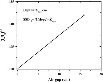
The schematic diagram of ISL method for SSDeff determination is shown in Figure 1. As it can be seen in this figure, having the values of
 $$\sqrt {{{I_{0} } \over {I_{g} }}} $$
for various air gaps, SSDeff can be determined through line slope and depth of measurement (z
max).Reference Khan
11
,
Reference Podgorsak
24
Graphical concept of inverse square law method as recommended by Khan et al.Reference Khan, Sewchand and Levitt 19

MC simulation
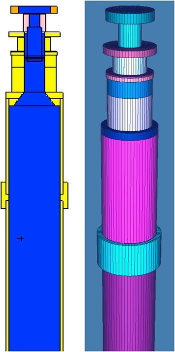
The MCNP Monte Carlo code was employed for simulating the geometry of the LIAC head. The geometric shape of the LIAC head and materials involved in MC simulation, as well as the energy spectra at different nominal energies and intensity profile of incident electrons on exit window, were provided by the manufacturer (Sordina SpA). The simulated geometry included exit window, scattering foil, monitor ion chamber, Mylar protecting layer and cylindrical electron applicator. The two- and three-dimensional views of the simulated model are shown in Figure 2. All of the available applicator sizes (3, 4, 5, 6, 7, 8 and 10 cm) and electron energies (6, 8, 10 and 12 MeV) were considered in the simulations. To obtain the SSDeff for different combinations of electron energy/applicator size, absorbed dose to z max was calculated for different air gaps, ranging from 0 to 16 cm with 4 cm steps, inside a PMMA phantom with the dimensions of 30×30×15 cm3. Size of scoring cells for dose calculation was considered as 0·5×0·5×0·2 cm3. Finally, following the ISL method, SSDeff was determined using Equation (3) and obtained MC data. Number of followed histories in each simulation was equal to 109. The statistical uncertainty in all of the simulations was less than 1%. The energy cutoff for electron and photon transport was set to 0·5 and 0·01 MeV, respectively.Reference Iaccarino, Strigari and D’Andrea 7
Two- and three-dimensional views of simulated light intraoperative accelerator head using MCNP MC code.

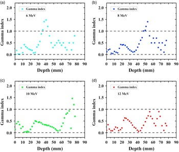
In order to validate the simulated model of the LIAC head, simulated percentage depth dose (PDD), along the clinical axis, for the 10 cm reference applicator at different nominal energies of 6, 8, 10 and 12 MeV were compared with those measured by ionometric dosimetry. This comparison was performed by gamma analysis. The dose difference and distance to agreement in the calculation of gamma index were considered as 3%, 3 mm, respectively (as recommended by Low et al.Reference Low and Dempsey 25 ). It should be mentioned that the gamma index calculations were performed in Gnuplot (version 4·4 patch level 3; Geeknet Inc., Fairfax,VA, USA) software environment using gamma_index executive file.
Measurement
To measure the PDDs related to the reference applicator at different energies, Advanced Markus ion chamber (TM 34045; PTW, Freiburg, Germany) was employed. The chamber was connected to a TANDEM digital electrometer (PTW) and the operating voltage was set to 300 V. Measurements were performed inside an automatic water phantom tank (MP3-XS; PTW) according to the recommendations of the IAEA TRS-398 protocol. 26 Chamber positions inside the phantom were automatically controlled using a TBA control unit (PTW). To suppress the effects of output variations during scans, a Semiflex ion chamber (TM 31010; PTW) was used as the reference detector.Reference Das, Cheng and Watts 27 The surface dose measurement was a major problem concerning the PDD measurements. The Advanced Markus chamber has a 1·3 mm thick entrance window (including waterproof cap, entrance foil and air gap between the cap and entrance foil) which make it impossible to directly measure the surface dose. Therefore, the surface dose was obtained through applying the cubic spline extrapolation method to the measured data at depths beyond 2 mm (taking into account the 1 mm water-equivalent window thickness of ion chamber).Reference Baghani, Aghamiri and Mahdavi 3
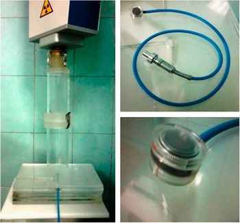
To determine the SSDeff for the 10 cm reference applicator at different energies, the effective point of the Advanced Markus chamber, the central point on inner surface of entrance foil, was placed at the z max corresponding to each electron beam energy (taking into account the 1 mm water equivalent window thickness of chamber)Reference Baghani, Aghamiri and Mahdavi 3 inside a PMMA slab phantom. The chamber was then connected to a digital electrometer (UNIDOS E; PTW) and chamber voltage was set to 300 V and absorbed dose for different air gaps from 0 to 16 cm was measured according to the recommendations of IAEA TRS-398 protocol. 26 Finally, the SSDeff for different energies were determined through ISL method and Equation (3). Employed setup for absorbed dose measurement inside the PMMA slab phantom is shown in Figure 3.
Experimental setup for absorbed dose measurement inside the polymethyl methacrylate slab phantom using Advanced Markus ion chamber.

RESULTS
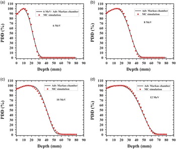
The simulated and measured PDD curves relating to the 10 cm diameter applicator for different electron energies of 6, 8, 10 and 12 MeV are shown in Figure 4. It should be mentioned that there was no air gap between the distal end of the applicator and phantom surface during the PDD measurements.
Measured and simulated percentage depth dose (PDD) curves related to the 10 cm reference applicator at different energies of 6 MeV (a), 8 MeV (b), 10 MeV (c) and 12 MeV (d). Abbreviation: MC, Monte Carlo.

The results of gamma analysis for validating the simulated model are also shown Figure 5. The results demonstrate for almost all of the depths, the value of gamma index is <1 for each studied energy. This fact confirms the agreement between the results of MC simulation and ionometric dosimetry and therefore, the validity of the simulated LIAC head.
The values of gamma index as a function of depth for different energies of 6 MeV (a), 8 MeV (b), 10 MeV (c) and 12 MeV (d).

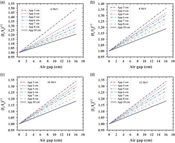
The plot of
 $$\sqrt {{{I_{0} } \over {I_{g} }}} $$
as a function of air gap for different combinations of electron energy/applicator size is shown in Figure 6. The maximum employed air gap was equal to 16 cm.
Implementation of ISL method for various applicator sizes at energies of 6 MeV (a), 8 MeV (b), 10 MeV (c) and 12 MeV (d).

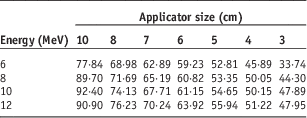
The values of SSDeff for various energies and applicator sizes, deduced from Figure 6 and according to the ISL, are reported in Table 1.
Simulated SSDeff for different combinations of electron energy/field sizes

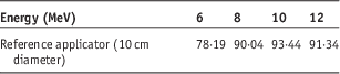
The values of experimentally determined SSDeff for 10 cm reference applicator at different energies are reported in Table 2.
Measured SSDeff for reference applicator at different energies of 6, 8, 10 and 12 MeV

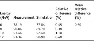
The difference between the measured and simulated SSDeff for the reference applicator at various energies are explained in Table 3. The results reported in this table demonstrate that there is a desirable accordance between the obtained results. The maximum and mean differences between the results were equal to 1·1 and 0·6%, respectively.
Comparison of the simulated and measured SSDeff for reference applicator at different energies of 6, 8, 10 and 12 MeV

DISCUSSION
According the obtained PDDs (Figure 4), with each increment of electron energy, dose gradient at depth considerably decreases while surface dose increases. Due to the different beam collimation system and a further reduction of electron mean energy, caused by multiple scattering of electrons from the applicator wall, the PDDs related to the LIAC dedicated IOERT accelerator fall more rapidly in comparison to the conventional radiotherapy accelerators.
The results in Figure 6 demonstrate that the slope of the straight line is decreased as the applicator size is increased. As demonstrated by Pimpinella et al.,Reference Pimpinella, Mihailescu and Guerra 28 the energy fluence of IOERT electron beam is decreased with increment of field size. Therefore, the absorbed dose at z max (I 0) is decreased with increasing the applicator size and therefore, it can be expected that the slope of straight line would be decreased.
As reported in Table 1, for a given small field size (up to 8 cm diameter) SSDeff is increased by increment of electron beam energy. This fact is due to the increased probability of electron scattering with decrement of beam energy. With increasing the beam energy, the contribution of scatter component is decreased and then, I
g
increases. Therefore, the slope of the straight line is decreased and according to Equation (3), SSDeff increases. For large applicator sizes (10 cm), the same trend is observed at low energies (6 and 8 MeV). But for high energies (10 and 12 MeV), the SSDeff may be steady or a little reduced by increasing the electron beam energy. In this situation, the contribution of scatter component in
 $$\sqrt {{{I_{0} } \over {I_{g} }}} $$
could be neglected and therefore, the SSDeff would be almost the same.
Furthermore, as it can be seen in Table 1, for a given energy, the SSDeff is increased with increment of applicator size. With increasing the field size, electron energy fluence at the exit of the IORT applicator is decreased and therefore, both I
0 and I
g
decrease. However, due to the increased multiple electron scattering from the applicator wall for small applicators in comparison with the large ones,
 $$\sqrt {{{I_{0} } \over {I_{g} }}} $$
for small fields would be greater than that of large fields. Therefore, the slope of the straight line would be increased with decrement of applicator size and finally SSDeff is reduced.
CONCLUSION
In this study, the values of SSDeff for different combinations of electron energy/applicator size related to the LIAC, a mobile dedicated IORT accelerator, were determined by ISL approach as recommended by Khan et al.Reference Khan, Sewchand and Levitt 19 From the obtained results, it can be concluded that the SSDeff of intraoperative electron beam is directly related to the electron beam energy and employed applicator size. The variations of SSDeff by changing the field size were evident, whereas, SSDeff was a mild function of electron beam energy. Variations of the SSDeff with electron energy and/or field size can be attributed to changing the electron energy fluence at the exit of IORT applicator and interaction with applicator wall.
Furthermore, the good agreement between the results of MC simulation and experimental data confirms the usability of MCNP MC code as an auxiliary tool for evaluating the dosimetric parameters of intraoperative electron beam and obtaining the related physical parameters such as the SSDeff.
Acknowledgement
The authors wish to thank from Khatam Hospital staff for their kindly supports, patience and cooperation.