NOMENCLATURE
- C Lα
-
lift slope factor
- a ∞
-
freestream speed of sound
- c
-
blade chord
- cref
-
reference blade chord
- C D0
-
overall profile drag coefficient
- Cq
-
blade sectional torque coefficient,
 $C_q = {\displaystyle \frac{{\rm d}C_Q}{{\rm d}(r/R)}}$
- CQ
-
rotor torque coefficient,
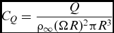
$C_Q = {\displaystyle \frac{Q}{\rho _\infty (\Omega R)^2 \pi R^3}}$
-
$\overline{C}_Q$
-
baseline rotor torque coefficient
- Ct
-
blade sectional thrust coefficient,
$C_t = {\displaystyle \frac{{\rm d}C_T}{{\rm d}(r/R)}}$
- CT
-
rotor thrust coefficient,
$C_T = {\displaystyle \frac{T}{\rho _\infty (\Omega R)^2 \pi R^2}}$
-
$\overline{C}_T$
-
baseline rotor thrust coefficient
- FoM
-
figure of merit,
$FoM = {\displaystyle \frac{C_T^{3/2}}{\sqrt{2}C_Q}}$
- g, h
-
constraint functions
- I
-
cost function [Equation (9)]
- k
-
turbulent kinetic energy
- ki
-
induced power factor
- K m, n
-
binomial coefficient [Equation (13)]
- Mtip
-
blade-tip Mach number,
$M_{\rm tip} = {\displaystyle \frac{V_{\rm tip}}{a_\infty }}$
- M ∞
-
freestream Mach number,
$M_\infty = {\displaystyle \frac{V_\infty }{a_\infty }}$
- Nb
-
number of blades
- Pi
-
induced power, Pi = Tvi
- Q
-
rotor torque
- R
-
rotor radius
- Re
-
Reynolds number, Re = V tip c ref/ν∞
-
${{\bm R}}$
-
flow equation residual vector
- r
-
radial coordinate along the blade span
-
$\hat{r}$
-
normalised radial coordinate along the blade span,
$\hat{r}=r/R$
- T
-
rotor thrust
- V tip
-
blade-tip speed, V tip = ΩR
- V ∞
-
freestream velocity
- vi
-
rotor induced velocity
-
${{\bm W}}$
-
flow solution vector
- w
-
weight factor in multi-point objective function
-
${{\bm X}}_{\!|\mathcal {S}}$
-
point vector
-
${{\bm \alpha }}$
-
design variables
- η
-
propeller propulsive efficiency,
$\eta = {\displaystyle \frac{C_T V_\infty }{C_Q V_{\rm tip}}}$
- λ i
-
downwash,
$\lambda = {\displaystyle \frac{v_i}{V_{\rm tip}}}$
-
${{\bm \lambda }}$
-
adjoint variables
- μ
-
axial ratio,
$\mu = {\displaystyle \frac{V_\infty }{V_{\rm tip}}}$
- ν∞
-
freestream kinematic viscosity
- ρ∞
-
freestream density
- Θ
-
local blade twist angle
- ΘIP twist
-
local ideal blade twist angle
- Θ nom
-
nominal twist
- θ75
-
blade pitch angle at r/R = 0.75
- ξ
-
vorticity
- Ω
-
rotor rotational speed
- nom
-
nominal value
- hm
-
helicopter mode
- am
-
aeroplane mode
- mp
-
multi-point
- ref
-
reference value
- tip
-
blade-tip value
-
$\mathcal {S}$
-
aerodynamic surface
- ∞
-
freestream value
- IP
-
induced power
- ANN
-
Artificial Neural Network
- AoA
-
Angle-of-Attack
- BEMT
-
Blade Element Momentum Theory
- CFD
-
Computational Fluid Dynamics
- CFL
-
Courant–Friedrichs–Lewy
- EIPM
-
Extended linear Interior Penalty function Method
- FGMRES-DR
-
Flexible Generalised Minimum Residual with Deflated Restarting
- HMB
-
Helicopter Multi-Block
- GA
-
Genetic Algorithm
- IDW
-
Inverse Distance Weighting
- ISA
-
International Standard Atmosphere
- NSGA-II
-
Non-dominated Sorting Genetic Algorithm II
- RANS
-
Reynolds Averaged Navier–Stokes
- SAMA
-
Surrogate-Assisted Memetic Algorithm
- SLSQP
-
Least-Square Sequential Quadratic Programming
- TRAM
-
Tilt-Rotor Aeroacoustics Model



Greek Symbols


Subscripts

Superscript
Acronyms
1.0 INTRODUCTION
The aerodynamic design of tiltrotor blades is a challenging task, requiring the best compromise in performance between hover and propeller modes(Reference Jones, Nielsen, Lee-Rausch and Acree1,Reference Droandi and Gibertini2) . In hovering flight, the blade aerodynamics is characterised by strong interaction with the rotor wake, resulting in a significant effect of the induced drag on the total drag(Reference Johnson3). The propeller mode, on the other hand, is dominated by strong compressibility effects, especially at high advance ratio, resulting in a prominent contribution of the profile and wave drag components(Reference McCormick4). As a consequence, to accurately capture the effect of the blade shape on the optimal rotor design, the use of high-fidelity flow models is required. Unlike in the case of helicopter and propeller blades, the aerodynamic optimisation of tiltrotor blades has not been the subject of considerable research. The present work analyses the contribution of the main blade shape parameters to the optimal performance of the tiltrotor using high-fidelity Computational Fluid Dynamics (CFD). It also demonstrates the use of gradient-based optimisation and the discrete adjoint for the efficient design of tiltrotor blades.
Aerodynamic optimisation needs large computational resources because each design point requires the solution of a set of partial differential equations. The choice of the optimisation algorithm is therefore crucial. Broadly speaking, the optimisation algorithms can be classified in gradient-based or gradient-free methods. Gradient-based methods usually require a limited number of flow evaluations(Reference Lyu, Xu and Martins5), and this makes them particularly attractive for complex aerodynamic optimisation problems. However, they need the computation of flow derivatives with respect to the design variables, which can be a very expensive task, unless the adjoint method is used. Also, gradient-based methods are local in nature, and they do not guarantee to find the global optimum. On the other hand, gradient-free methods are simpler to implement because they do not require flow derivatives, and some of them ensure to reach the global optimum. Nevertheless, they typically need two to three orders of magnitude more objective function evaluations than gradient-based methods(Reference Zingg, Nemec and Pulliam6). Gradient-free methods are therefore effective only when coupled with low-fidelity or reduced-order models, for which the evaluation of functionals depending upon the flow solution is cheap. It can be stated that gradient-free methods are more appropriate to the preliminary design of the aircraft, while gradient-based methods, coupled with high-fidelity flow models, may be used at more advanced stages of the design process.
Gradient-based methods have been widely employed for optimisation of rotors in hover, as in the work of Walsh et al (Reference Walsh, Bingham and Riley7), Zibi et al (Reference Zibi, Defresne and Costes8), and more recently in Le Pape et al (Reference Pape and Beaumier9), Choi et al (Reference Choi, Potsdam, Lee, Iaccarino and Alonso10) and Dumont et al (Reference Dumont, Pape, Peter and Huberson11). These works not only demonstrated the efficiency of gradient-based optimisation methods for blade design but also highlighted the dependency of the final design upon the selected initial design point. This is due to the behaviour of gradient-based algorithms, which may fail to find the global optimum and converge to a local extremum of the objective function. Several authors tried to overcome this drawback, developing strategies to select the best starting point in the design space(Reference Schwabacher, Ellman and Hirsh12,Reference Chen and Lee13) . Application of gradient-free methods can be found in the work of Imiela(Reference Imiela14), who optimised the ONERA 7A model rotor blade and compared results from both gradient and gradient-free methods, and in the work Johnson et al (Reference Johnson and Barakos15), who optimised the UH60-A rotor blade to reduce peak normal and torque loads using a Genetic Algorithm (GA) and a reduced-order model based on Artificial Neural Networks (ANN).
For the optimisation of propeller blades, the work of Cho et al (Reference Cho and Lee16) used the Extended linear Interior Penalty function Method (EIPM) in conjunction with panel and vortex lattice methods to find the optimal blade twist and chord distributions. Coupled aeroacoustic and aerodynamic optimisation of propeller blades was instead carried out by Marinus et al (Reference Marinus, Roger and der Braembussche17) using a gradient-free method, where aerofoil shapes, twist and chord distributions were simultaneously optimised at multiple operating conditions.
For the tiltrotor to be commercially viable, its rotor blades must be designed to efficiently work both in helicopter and aeroplane modes. This makes the design of tiltrotor blades particularly challenging, because the aerodynamic characteristics of helicopter rotor and propeller blades are significantly different, and the optimal values of the main shape parameters (e.g. twist and chord distributions, sweep, anhedral) can be different in the two cases. It follows that the blade design requires the solution of a multi-objective optimisation problem, where the objective functions are suitable measures of the performance at selected flight conditions in both helicopter and aeroplane modes. A multi-objective optimisation of the ERATO blade in conjunction with a gradient-based optimiser was put forward by Leon et al (Reference Leon, Le Pape, Desideri, Alfano and Costes18), seeking to maximise the Figure of Merit (FoM) in hover and minimise the rotor power in forward flight. Wilke(Reference Wilke19) applied single- and multi-objective techniques for the variable-fidelity optimisation of a helicopter rotor. Single optimisations of hover and forward flight blades have shown a detrimental performance when used in the opposite flight condition. However, the shape obtained with the multi-objective optimisation technique was a compromised design of both antagonistic objectives. To reduce computational cost, the multi-objective optimisation can be reduced to a single-objective optimisation by considering the weighted sum of the objective functions at each flight condition. Higher weights are assigned to the flight conditions that cover the most part of the typical tiltrotor mission. This strategy is usually referred to as ‘multi-point’ optimisation.
An application of multi-objective optimisation to the design of a generic tiltrotor blade is reported in Droandi et al (Reference Droandi and Gibertini20), where a Non-dominated Sorting Genetic Algorithm II (NSGA-II) was used in conjunction to a Blade Element Momentum Theory (BEMT) solver. The BEMT solver allowed for a quick evaluation of the flow solution at each design point, but the model cannot account for the effect of all the blade shape parameters, such as the sweep angle, which requires a higher-fidelity flow modelling. The aerodynamic optimisation of the XV-15 rotor blades was investigated by Massaro et al (Reference Massaro and D’Andrea21) using a Surrogate-Assisted Memetic Algorithm (SAMA), combined with a panel method for the blade aerodynamics. Aerofoil shapes, twist and chord distributions, and anhedral and sweep angles were considered for the maximisation of the FoM and the propeller propulsive efficiency (η). They showed that a compromise solution can be selected from the Pareto front, which has 3.2% higher FoM in hover and 6.5% higher η in aeroplane mode with respect to the XV-15 baseline blade. Multi-point optimisation based on a gradient method was carried out by Jones et al (Reference Jones, Nielsen, Lee-Rausch and Acree1) for the Tilt-Rotor Aeroacoustics Model (TRAM)(Reference Booth, McCluer and Tadghighi22). They employed the unstructured FUN3D flow solver(Reference Anderson and Bonhaus23,Reference Nielsen24) , coupled with a discrete adjoint solver, to determine the optimal aerofoil shapes, twist and taper.
In this work, we perform both single- and multi-point optimisations of the XV-15 tiltrotor blade with different sets of design variables to provide a breakdown of the impact that different geometrical features have on the optimal design. In our opinion, this will give to the engineers more insight about tiltrotor blade design. The employed optimisation framework is founded on a Least-Square Sequential Quadratic Programming (SLSQP) algorithm, coupled with the HMB3 CFD solver and to a discrete adjoint method with full accounting of the Menter’s k-ω turbulence model coupling terms. The linear system for the adjoint variable is solved using a Flexible Generalised Minimum Residual solver with Deflated Restarting (FGMRES-DR) nested with GMRES-DR as a preconditioner. To reduce the computational cost, we solved the hover and propeller flows by casting the equations as a steady-state problem in a noninertial reference frame. Rigid rotor blades were considered in this study, based upon the good agreement obtained with the experiments, as shown in Part I. Results are presented for a range of design points, which includes medium and high thrust hovering flight conditions, and a high axial ratio propeller condition. A detailed introduction of the XV-15 can be found in Part I.
The structure of this paper is as follows: Section 2 describes the optimisation framework, the objective and constraint functions, and the blade shape parametrisation technique. Section 3 presents the numerical results. At first, single-point optimisation results are shown, to investigate the effect of the twist and chord/sweep distributions on the helicopter and aeroplane modes tiltrotor performance. Then, multi-point optimisation results are presented. Finally, conclusions and future work are outlined in Section 4.
2.0 OPTIMISATION FRAMEWORK
2.1 Objective and constraint functions
The objective functions for the tiltrotor blade optimisation should be measures of the performance in helicopter and aeroplane modes. For the helicopter mode, the FoM is used as an indicator of the rotor efficiency because it represents the ratio between the ideal absorbed power in hovering predicted by the momentum theory and the actual absorbed power:
 $$\begin{equation}
{\rm FoM} = {\displaystyle \frac{C_T^{3/2}}{\sqrt{2}C_Q}}
\end{equation}$$
In aeroplane mode, on the other hand, we use the propeller propulsive efficiency, which is the ratio between the useful power output of the propeller and the absorbed power:
 $$\begin{equation}
\eta = {\displaystyle \frac{C_T V_\infty }{C_Q V_{\rm tip}}}
\end{equation}$$
After the preliminary sizing of the tiltrotor, the rotor thrust in hovering flight and at cruise condition are typically fixed. Therefore, the optimisation should not alter these values, and a constraint on the thrust must be imposed. It follows that the problem of maximising the FoM in helicopter mode and the propeller propulsive efficiency in aeroplane mode can be casted as a minimisation problem for the torque coefficient in either cases. The single-point design problem then reads:
 $$\begin{equation}
\left\lbrace \begin{array}{l}
{\rm Minimise\, I = {\displaystyle \frac{C_Q}{\overline{C}_Q}}\, subject\, to}\\
C_T=\overline{C}_T\\
\end{array} \right.
\end{equation}$$
Note that the torque coefficient CQ
is normalised by the baseline rotor torque coefficient
 $\overline{C}_Q$
so that the cost function I is O(1). The quantity
 $\overline{C}_T$
denotes the thrust coefficient of the baseline rotor.
For the multi-point optimisation of the tiltrotor, a composite objective function I mp is constructed as a weighted sum of the cost functions associated to N selected flight conditions, representing both helicopter and aeroplane operational modes:
 $$\begin{equation}
I_{\rm mp}= \sum _{i=1}^{N} w_i {\displaystyle \frac{C_{Q,i}}{\overline{C}_{Q,i}}} ,
\end{equation}$$
where wi , i = 1, . . ., N represent the weighting factors, which are chosen so that
 $$\begin{equation}
\sum _{i=1}^{N} w_i = 1
\end{equation}$$
The multi-point design problem is then stated as follows:
 $$\begin{equation}
\left\lbrace \begin{array}{l} {\rm{Minimise\, {\textit I}_{mp}\, subject\, to}}\\
C_{T,i}=\overline{C}_{T,i}, \quad i=1,\dots ,N\\
\end{array} \right.
\end{equation}$$
Any number N of flight conditions can be considered for the multi-point optimisation. For instance, it is possible to include low- and high-disc loading cases in hover, and low- and high-speed cases for the aeroplane mode. However, in the present work, we consider only the case N = 2, with one hovering and one aeroplane mode condition. The objective function will be written as:
 $$\begin{equation}
I_{\rm mp}= w_{\rm hm} {\displaystyle \frac{C_{Q,{\rm hm}}}{\overline{C}_{Q,{\rm hm}}}} + w_{\rm am} {\displaystyle \frac{C_{Q,{\rm am}}}{\overline{C}_{Q,{\rm am}}}} ,
\end{equation}$$
where the subscript ‘hm’ refers to the helicopter mode and the subscript ‘am’ refers to the aeroplane mode.
2.2 Optimisation tools chain
An economic way to obtain the flow gradients with CFD is the adjoint method, which reduces the cost function derivatives evaluation to about the cost of the base flow solution, regardless of the number of design variables. The underlying idea is to write explicitly the cost function I in terms of the flow variables
 ${{\bm W}}$
and of the design variables
 ${{\bm \alpha }}$
, that is,
 $I=I({{\bm W}}({{\bm \alpha }}),{{\bm \alpha }})$
. The flow variables are subject to satisfy the fluid dynamics governing equations (e.g. the Reynolds-Averaged Navier–Stokes equations) written in compact form as
 $$\begin{equation}
{{\bm R}}({{\bm W}}({{\bm \alpha }}),{{\bm \alpha }}) = 0
\end{equation}$$
Formally, taking the derivative of I with respect to
 ${{\bm \alpha }}$
, we obtain:
 $$\begin{equation}
{\displaystyle \frac{{\rm d} I}{{\rm d} {{\bm \alpha }}}} = {\displaystyle \frac{\partial I}{\partial {{\bm \alpha }}}} + {\displaystyle \frac{\partial I}{\partial {{\bm W}}}} {\displaystyle \frac{\partial {{\bm W}}}{\partial {{\bm \alpha }}}}
\end{equation}$$
By introducing the adjoint variable
 ${{\bm \lambda }}$
as the solution of the following linear system:
 $$\begin{equation}
\left( {\displaystyle \frac{\partial {{\bm R}}}{\partial {{\bm W}}}} \right) ^{\rm T} {{\bm \lambda }}= - \left( {\displaystyle \frac{\partial I}{\partial {{\bm W}}}} \right) ^{\rm T}
\end{equation}$$
Equation (9) can be rewritten as:
 $$\begin{equation}
{\displaystyle \frac{{\rm d} I}{{\rm d} {{\bm \alpha }}}} = {\displaystyle \frac{\partial I}{\partial {{\bm \alpha }}}} + {{\bm \lambda }}^{\rm T} {\displaystyle \frac{\partial {{\bm R}}}{\partial {{\bm \alpha }}}},
\end{equation}$$
which is known as the dual form of the sensitivity equation. The computation of the derivatives of the functional I is reduced to the solution of the linear sensitivity problem (10)-(11). The computational cost scales with the number of outputs because the right-hand side of the linear system (10) depends on I, but it is independent of the input parameters. The linear system (10) is usually hard to compute because the Jacobian matrix
 $\partial {{\bm R}}/ \partial {{\bm W}}$
is characterised by a high stiffness, and the solution time can be comparable to that of the base flow.
The HMB3 flow solver embeds two methods for solving the linear system (10). The first is an implicit, fixed-point iteration scheme(Reference Biava, Woodgate and Barakos25), while the second is a nested FGMRES-DR/GMRES-DR Krylov-subspace method(Reference Biava and Barakos26). Both adjoint solvers can be interfaced to a gradient-based optimiser to efficiently solve a design problem, which amounts in minimising an objective function I (e.g. drag, power), possibly subject to constraints (e.g. fixed lift, fixed thrust). In the current implementation, the optimisation problem is solved using a Least-Square Sequential Quadratic Programming (SLSQP) algorithm(Reference Kraft27).
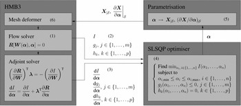
The design optimisation procedure is described in Fig. 1 and can be summarised as follows.
-
1. The flow around the aerodynamic surface
$\mathcal {S}$
to be optimised (e.g. aerofoil, blade) is solved. For the first iteration, this solution represents the baseline flow solution.
Figure 1.Flow chart of the optimisation process.
-
2. The objective function I and the constraints gj , j ∈ {1, . . ., m}, hk , k ∈ {1, . . ., p} are evaluated from the flow solution.
-
3. The adjoint problem is solved to compute the gradients
${\rm d} I / {\rm d} {{\bm \alpha }}$
,
${\rm d} g_j / {\rm d} {{\bm \alpha }}$
, j ∈ {1, . . ., m},
${\rm d} h_k / {\rm d} {{\bm \alpha }}$
, k ∈ {1, . . ., p}. -
4. The cost functional, the constraints and their gradients are fed to the gradient-based optimiser, which produces a new set of design variables
${{\bm \alpha }}$
, corresponding to a design candidate in the search direction. -
5. Based on the new values of the design variables
${{\bm \alpha }}$
, the point vector
${{\bm X}}_{\!|\mathcal {S}}$
describing the surface
$\mathcal {S}$
is updated, as well as the derivatives of these points with respect to the design variables
$(\partial {{\bm X}}/ \partial {{\bm \alpha }})_{|\mathcal {S}}$
. -
6. A mesh deformation algorithm, based on Inverse Distance Weighting (IDW)(Reference Biava and Barakos26), computes the new volume mesh points positions
${{\bm X}}$
, and the derivatives
$\partial {{\bm X}}/ \partial {{\bm \alpha }}$
. A new surface
$\mathcal {S}$
is generated to close the cycle.


Steps 1-6 are repeated for several design cycles until convergence criteria are met. These criteria include checks on the objective function gradient module, and checks on the variation of the design variables and of the objective function between successive cycles of the optimisation process.
2.3 Parametrisation technique
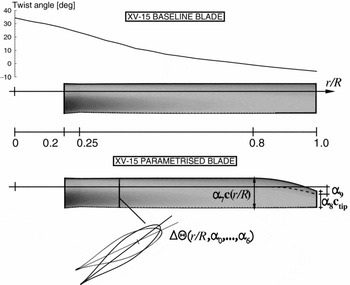
The parametrisation technique used here allows for variations of the blade twist, chord and sweep distributions (see Fig. 2). The shape of the blade sections, coning and collective pitch angles, however, were not accounted for in this work. The twist parametrisation considers the perturbation of the blade section angle-of-attack with respect to the baseline blade. This twist perturbation ΔΘ is expressed in terms of a Bernstein polynomial expansion, due to its simplicity and the smoothness of the resulting design space:
 $$\begin{equation}
\Delta \Theta (\hat{r}) = \sum _{m=0}^{n} \alpha _m K_{m,n} \hat{r} ^m (1-\hat{r})^{n-m},
\end{equation}$$
where
 $\hat{r}$
is the nondimensional coordinate along the blade span, which has value 0 at the rotation axis, and a value 1 at the blade tip. The symbol K
m, n
denotes the binomial coefficient, which is defined as:
 $$\begin{equation}
K_{m,n} = \left( \begin{array}{c}n \\
m \end{array} \right) = {\displaystyle \frac{n}{m(n-m)}}
\end{equation}$$
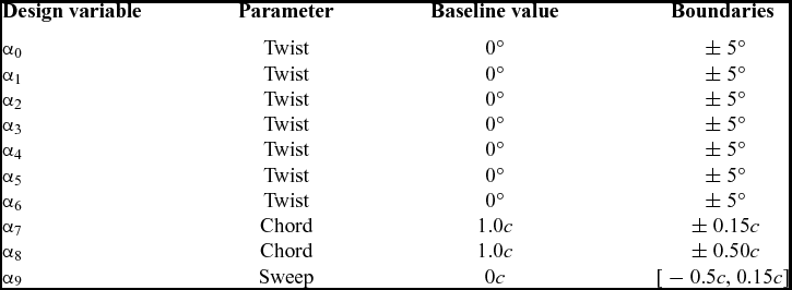
The polynomial expansion coefficients α m , m = 0, . . ., n, represent the design variables for the twist. In all the presented cases, seven design variables were used to represent the twist perturbation (α0, . . ., α6). The values of the design variables for the twist perturbation are limited to the range ± 5°.
Schematic view of the twist, chord and sweep parametrisation for the XV-15 tiltrotor blade.

Two design variables, α7 and α8, were used to describe the variation of the blade chord. The former represents the relative variation of the blade chord between
 $\hat{r}=0.25$
and
 $\hat{r}=0.80$
. The latter is the relative chord variation at the tip, and a parabolic shape is imposed between
 $\hat{r}=0.8$
and
 $\hat{r}=1$
. The blade root chord, at
 $\hat{r}=0.2$
, is kept fixed, and the chord variation is interpolated linearly between
 $\hat{r}=0.2$
and
 $\hat{r}=0.25$
. The design variable α7 is limited to 1 ± 15%, while α8 can vary in the range 1 ± 50%.
Finally, one design variable α9 is used to control the blade sweep distribution between
 $\hat{r}=0.8$
and
 $\hat{r}=1$
. Its value represents the sweep at
 $\hat{r}=1$
, and a parabolic sweep distribution is imposed in the range [0.8, 1]. The value of the design variable α9 is limited to [ − 0.5c, 0.15c], where a positive number denotes a shift of the blade section in the direction pointing from trailing edge to leading edge. Table 1 lists the design variables α along with their baseline and boundary values.
Design variables along with their baseline and boundary values employed to describe the variation of the blade twist, chord, and sweep distributions

3.0 RESULTS AND DISCUSSION
The performance of the XV-15 rotor can be adequately captured by the employed HMB solver(Reference Lawson, Steijl, Woodgate and Barakos28-Reference Steijl, Barakos and Badcock30) as demonstrated in Part I of this paper.
3.1 Ideal twist using blade element momentum theory
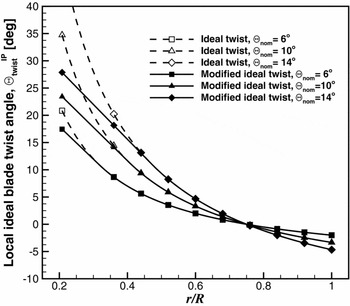
Blade element momentum theory(Reference Leishman31) refers to an aerodynamic loading distribution for minimum induced power (which ignores profile and wake losses), and demonstrates an ‘ideal’ rotor blade twist of following form:
 $$\begin{equation}
\Theta _{{\rm twist}}^{{\rm IP}}=\Theta _{nom}\bigg (\frac{1}{r/R}-4/3\bigg )
\end{equation}$$
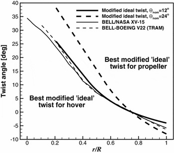
A range of these distributions (herein referred as ‘ideal’ twist for convenience) is shown in Fig. 3 as function of the nominal twist Θ nom . However, these ideal distributions generate impractical inboard values and so a minor modification can be made (herein referred as modified ‘ideal’ twist). Blade element theory evaluations reveal that such approximations have a negligible effect on the hover and propeller performance for low and moderate twist, whilst at the higher twist values prevent excessive local incidences for the inboard blade sections. Consequently, efficient inboard aerofoils can be designed for these reduced incidence ranges, and in reality the result is higher performance than would be achieved with the unmodified theoretical ideal distribution. The linear inboard approximation is therefore confirmed as reasonable.
Modified ‘ideal’ twist distributions for minimum power with a linear inboard approximation.

Blade element theory evaluations for the rotor performance of these twist distributions reveal a conflicting requirement between the hover and propeller design conditions; there will exist an optimum ideal twist distribution for a tiltrotor blade in hovering conditions and a different, much higher, twist distribution for the most efficient operation in propeller mode. In order for a tiltrotor aircraft to be commercially successful, it is difficult to imagine any scenario where one of these distributions would completely ‘win’ over the other, and therefore it would seem logical for a rotor designer to seek some compromise which would provide an acceptable performance trade between these two distinct aircraft operating conditions.
An optimum concept distribution can be derived which merges the best inboard distribution for hover conditions (labelled with modified ideal twist Θ nom = 12° in Fig. 4) with an increased outboard (and overall) blade twist, which provides the propeller efficiency (labelled with modified ideal twist Θ nom = 24° in Fig. 4). The extent to which the outboard blade is twisted will depend on the required aircraft cruise speeds and the trade-off with hover performance. In reality, the increased outboard twist is often beneficial for the hover case because it off-loads the blade tip, postponing flow separation and stall, which are not accounted for in the basic theory.
The conflicting tiltrotor blade twist requirements for efficient operation in two distinct flight modes and comparison with two successful tiltrotor blade designs(Reference Johnson32,Reference Acree33) .

The theory is based on the idea of a minimum induced power, which forms the majority of the total power consumption for a tiltrotor blade in hover with very high disk loading and so the overall rotor performance is very sensitive to the twist distribution (i.e. big returns for relatively small twist variations). Despite that the BEMT does not resolve the blade tip vortex, the combine twist distribution is a good starting point. However, for an actual design further refinements would of course follow, for example to accommodate design choices for the:
-
• Tip region (based on detailed simulations and tip shape selection).
-
• Root region (based on the imposed constraints from blade structural design).
-
• Secondary performance requirements (autorotation, acoustics).
In addition, the aerofoil family, their radial distribution and the blade planform (which have been fixed for the purposes of this discussion) will also have a major influence on the final performance.
In Fig. 4, the aforementioned twist distribution combining the inboard (based on hover) and outboard (based on propeller) twists, is compared with two successful tiltrotor blade designs of the Bell-Boeing V-22 (TRAM) and Bell/NASA XV-15 and the similarities are clear for the inboard distributions (probably set for best hover performance) and with the outboard twist apparently set for whichever propeller conditions were important for the specific aircraft operating conditions.
3.2 XV-15 blade mesh
A mesh generated using the Chimera technique was used for the design study of the XV-15 rotor, and it was composed by a periodic background mesh and a component mesh for the blade. The use of an overset grid method allowed to employ the same mesh for both the helicopter and the aeroplane modes, since the blade pitch angle could be easily changed by rotating the Chimera component mesh containing the blade. This mesh was used in the Part I of this work to analyse the aerodynamic performance of the XV-15 rotor. It was found that, despite the relatively small size (6.2 million cells per blade), there was a good correlation between the experiments and the CFD predictions. For this reason, the same mesh was also employed for the aerodynamic optimisation study.
Table 2 shows a breakdown of the number of cells (per blade) used for the background mesh and for the body-fitted mesh around the XV-15 rotor blade. A more detailed description of the computational domain, boundary conditions and meshing parameters can be found in Part I.
Meshing parameters for the XV-15 mesh rotor blade

3.3 Design cases
Representative flight conditions in hover and propeller modes were selected from the available literature on the XV-15(Reference Maisel, Giulianetti and Dugan34). For the hover mode, the tip Mach number was set to 0.69, and two blade collective pitch angles were considered, 7° and 10°, corresponding to a medium and a high disc loading, respectively. The Reynolds number, based on the reference blade chord of 14 inches and on the tip speed, was 4.95 × 10⁶. The cruise condition was modelled at 20,000ft (ISA+0°), with a tip Mach number of 0.60, axial ratio of 0.759 and a collective pitch angle of 47°. The Reynolds number for this case was 2.2 × 10⁶, again based on the reference blade chord and rotor tip speed (with no account for the axial velocity).
All the flow solutions were computed by solving the RANS equations, coupled with the Menter’s k-ω SST turbulence model(Reference Menter35). The flow equations were integrated with the implicit dual-time stepping method of HMB3, using a pseudo-time Courant–Friedrichs–Lewy (CFL) equal to 4 for the helicopter mode computations, and equal to 2 for the aeroplane mode. The linear system (10) for the adjoint variable was solved by means of the nested Krylov-based solver FGMRES-DR(300,100)-GMRES(40), where the number of inner GMRES iterations was limited to 40. Typically, 2,500 outer iterations were necessary to drop the residual by 6 orders of magnitude (as found to be necessary in previous works(Reference Biava, Woodgate and Barakos25)) for the hover adjoint solutions, while about 300 iterations were necessary to reach the same convergence level for the aeroplane mode adjoint solutions.
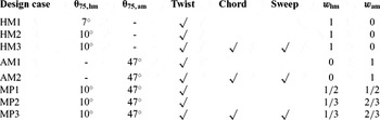
Table 3 lists the design cases considered for the aerodynamic optimisation of the XV-15 tiltrotor blade, along with the used design variables (twist, chord and sweep) and the objective function weights in the case of multi-point optimisation (w hm for the helicopter mode, and w am for the aeroplane mode). Cases HM1 and HM2 evaluate the impact of the twist distribution on the hovering performance, while HM3 the potential contribution of the chord and sweep. Likewise, cases AM1 and AM2 show the effect of the twist, combined with that of chord and sweep, on the propeller performance. The possibility of selecting a twist distribution that is optimal for both hover and aeroplane modes is investigated through the multi-point design cases MP1 and MP2. The two cases differ only in the selection of the weights associated to the two operational conditions in the composite objective function. Finally, in case MP3, the effect of the chord and sweep is accounted for in the multi-point optimisation.
Design cases considered in the aerodynamic optimisation study

3.4 Helicopter mode
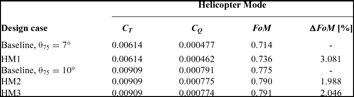
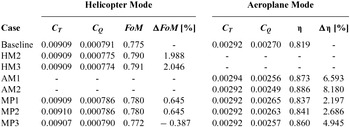
The single-point design cases for the helicopter mode are discussed here. Table 4 compares the performance of the baseline XV-15 blade at θ75 = 7° and θ75 = 10°, with those resulting from single-point optimisations of the blade. The optimal twist distribution was computed for both collective angles (cases HM1 and HM2), while for the collective angle θ75 = 10° only, the optimal chord and sweep distributions were also determined (case HM3).
Results of single-point design cases for the helicopter mode

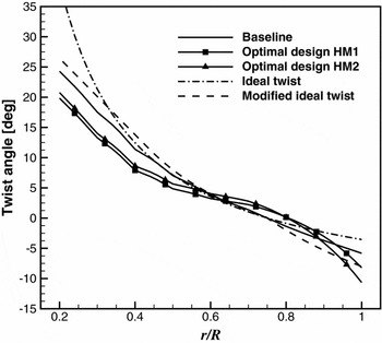
Cases HM1 and HM2 converged in about nine design cycles and resulted in an increase of the FoM of 3.081% and 1.988% at the respective design conditions. The optimal twist distributions for the two cases are shown in Fig. 5, where the baseline and ideal and modified twist curves are also reported for comparison. The overall similarity between theory-based ideal twist distributions, confirms the validity of the optimisation process in independently generating a realistic tiltrotor blade twist distribution. The local variations near the blade tip are most likely due the fact that only the CFD simulations will have captured the behaviour of the blade-tip 3D effects and the wake-induced effects near 80%R. The baseline blade follows closely the ideal distributions for r/R between 0.4 and 0.8. It has, however, a linear twist in the inboard region, and a slightly off-loaded tip with respect to the ideal. For both HM1 and HM2 cases, the optimal twist has the same linear behaviour as the baseline at the inboard region (r/R < 0.4), but the optimal twist value is lower. Substantial differences are instead observed outboard. Also, the optimal blades present a more pronounced off-loading at the tip, for r/R > 0.9, and an increased loading in the region between r/R = 0.6 and r/R = 0.9, which is necessary to satisfy the fixed thrust constraint.
Plot of ideal, baseline and optimal blade twist distributions.

To better understand the mechanism that leads to the optimal design, let us assume as a measure of the contribution of each blade section to the overall rotor efficiency the ratio Ct/Cq
, where
 $C_t(\hat{r}) = {\rm d} C_T / {\rm d} \hat{r}$
is the local contribution to the thrust, and
 $C_q(\hat{r}) = {\rm d} C_T / {\rm d} \hat{r}$
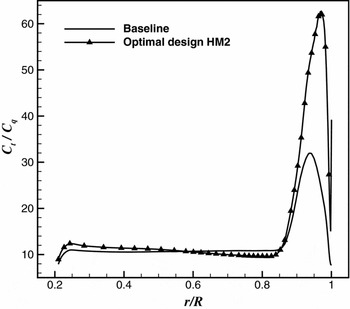
the local contribution to the torque. Figure 6 shows the Ct/Cq
curve for the baseline blade and for the optimal design HM2. The off-loading of the tip allowed all blade sections for r/R > 0.85 to work more efficiently, locally providing a contribution to the overall thrust with lower absorbed power penalty.
Ct/Cq curve for the baseline blade and optimal design case HM2.

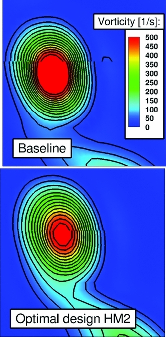
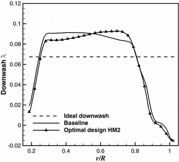
The modification of the twist distribution in the tip region also impacts on the tip vortex generation. Figure 7 reports the contours of the vorticity vector magnitude in a plane behind the blade, for both the baseline and the optimal design HM2. It is evident that the tip vortex for the optimal design is weaker and that the trajectory has been altered. The effect of the tip can also be observed on the induced velocity distribution in the tip path plane, which is shown in Fig. 8. The induced velocity at the rotor plane was obtained and averaged using the CFD velocity field at several upstream and downstream locations. Further information about the method used can be found in Ref. 36.
Vorticity contours of the blade-tip vortex for baseline blade and design case HM2.

Comparison between ideal, baseline and optimal induced velocity distribution.

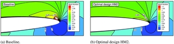
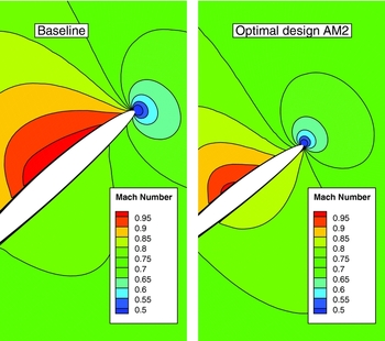
An important consequence of the tip off-loading is that the optimal blade presents only a very mild shock at the tip region, while the baseline blade exhibits a rather strong shock, as confirmed by Fig. 9, which shows the Mach number distribution at r/R = 0.95.
Contours of Mach number at blade section r/R = 0.95 for the baseline blade (left) and design case HM2 (right).

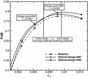
The performance of the optimal design blades HM1 and HM2 was assessed over the whole range of collective angles. For both cases, the FoM curves are compared to that of the baseline blade in Fig. 10. As expected, the blade optimised at 7° collective performs better at low values of the thrust coefficient, while the blade optimised at 10° is more efficient at higher disc loadings. It is interesting to note that the optimised blades perform better than the baseline not only at the design points but also over the whole range of considered thrust coefficient values.
Figure of merit of the baseline and optimal designs HM1 and HM2.

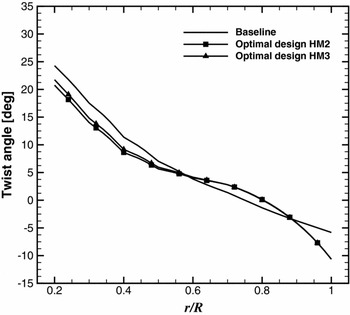
The design case HM3 includes the chord and sweep distributions in the blade parametrisation. It converged after 19 design cycles, and the resulting optimal blade is characterised by a reduction of the blade chord of 1.3% for r/R < 0.8, and of 4.6% at the tip. The rotor FoM is 2.046% higher than the baseline, showing a very limited benefit with respect to the pure twist optimisation, which suggests that the chord and the sweep play a secondary role in the hovering rotor performance. Figure 11 shows the comparison of the twist distribution of the baseline and of the optimal design cases HM2 and HM3. The design case HM3 presents higher AoA at the inboard part of the blade, up to r/R = 0.7, with a small difference observed at the outboard region.
Plot of baseline and optimal blade twist distributions.

3.5 Aeroplane mode
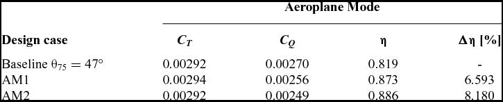
Like for the helicopter mode, single-point optimisation cases were performed initially considering the twist only, whereas chord and sweep distributions were added at a second stage. Table 5 reports a comparison between the performance of the baseline XV-15 blade at θ75 = 47° and μ = 0.759, and the results from single-point optimisations.
Results of single-point design cases for the aeroplane mode

The optimisation of the blade twist distribution AM1 increases the propeller propulsive efficiency of the rotor by 6.593%. The inclusion of the chord and sweep in the parametrisation (design case AM2) allows for a further improvement, with an increase of 8.180% over the baseline. In aeroplane mode, in fact, the rotor torque is dominated by transonic compressibility effects, which can be influenced by altering the chord and by modifying the local normal Mach number through a swept tip. Both optimisation cases converged in about 30 design cycles.
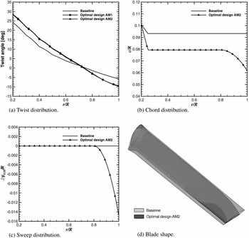
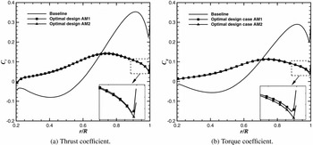
The optimal twist for the two cases is plotted in Fig. 12(a), and the baseline twist distribution is superimposed. Despite a small difference near the blade root, the two distributions are very similar. Unlike for the helicopter mode, the optimal twist for the aeroplane mode is approximatively linear over all the blade span. Compared to the baseline, the optimal distribution presents higher AoA at the inboard part of the blade, up to r/R = 0.7, and lower AoA outboard. The large increase of the AoA at the blade root is due to the fact that the baseline blade is working as a windmill at the selected cruise condition, as shown by Fig. 13, which displays the distribution of Ct and Cq over the blade span.
Comparison of (a) twist, (b) chord, (c) sweep distributions and (d) blade shape between baseline and design case AM2.

Blade sectional thrust coefficient (left) and torque coefficient (right) for the baseline blade and design cases AM1 and AM2.

Figure 12 shows the twist, chord sweep distributions of the optimal blade for design case AM2. The figure also contains a comparison between the baseline and the optimal blade shape. A reduction of the blade chord of about 15% is found by the optimiser. The chord is further reduced at the tip, where it is 34% less than the baseline, to create a swept tip shape (see Fig. 12(b)). This shape modification, together with a backward shift of the quarter chord line introduced by the sweep design variable (see Fig. 12(c)) tend to limit the compressibility effects and to reduce the wave drag as observed in Fig. 14.
Contours of Mach number at blade section r/R = 0.95 for the baseline blade and design case AM2.

3.6 Multi-point optimisation
We finally discuss the results of the multi-point optimisations, where a composite objective function is used to weigh the performance indices of the helicopter and aeroplane mode conditions (see Equation (7)). Three cases were considered: two pure twist optimisations, which differ for the weights selection (cases MP1 and MP2), and a case with the same weights as MP2, but which includes the optimisation of the chord and sweep. Case MP1 has equal weights for the helicopter and aeroplane modes (w hm = 1/2 and w am = 1/2), while cases MP2 and MP3 weigh more the cruise condition (w hm = 1/3 and w am = 2/3).
Table 6 reports the optimised values of the thrust and torque coefficients, FoM and propeller propulsive efficiency, along with their relative changes over the baseline values. The single-point optimisations are also shown for comparison. The pure twist optimisations (MP1 and MP2) result in an FoM increment of 0.645% for both cases, while the propeller propulsive efficiency increases by 2.197% when the operational modes are weighted equally, and by 2.686% when the cruise condition is weighted more. All the three optimisation cases took about 10 design cycles to reach a converged solution.
Results of single- and multi-point design cases

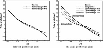
Figure 15(a) shows the comparison of the twist distribution of the baseline and of the optimal design cases MP1 and MP2. The two multi-point results are very similar, almost identical at the resolution used for the plot. The multi-point result should be compared to the helicopter and aeroplane mode single-point optimal designs, which are reported in Fig. 15(b). At the inboard sections, for r/R < 0.6, the multi-point optimal twist curve lies halfway between the helicopter and aeroplane mode curves. At the tip region, it has a nonlinear behaviour similar to the helicopter mode optimal solution but less pronounced.
Comparison of baseline and optimal blades twist distributions for the multi-point cases (left) and for the single-point cases (right).

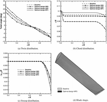
The design case MP3 includes the chord and sweep distributions in the blade parametrisation, and the resulting optimal blade has 0.387% lower FoM and 4.945% higher propeller propulsive efficiency than the baseline. Compared to the pure twist optimisation, there is a significant benefit because of the increase of the aeroplane mode performance, with only a small penalty on the helicopter mode. Figure 16 shows a comparison of the twist, chord and sweep distributions between the optimal blade for the design cases HM3, AM2 and MP3. The figure also contains a comparison between the baseline and the optimal blade shape MP3. The multi-point optimised blade has a swept tip, where the chord has been reduced by about 5%. This value is similar to that obtained for the single-point helicopter mode optimisation but lower than the optimal for the aeroplane mode. Nevertheless, it is sufficient to limit the compressibility effects at the tip region encountered in aeroplane mode at high advance ratio.
Comparison of (a) twist, (b) chord, (c) sweep distributions and (d) blade shape between baseline and design cases HM3, AM2 and MP3.

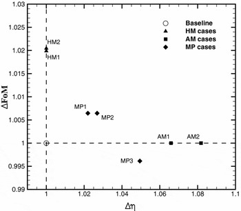
Figure 17 shows the improvements of FoM and η for all HM, AM and MP design cases. Note that for the single-point optimisation cases, values of 1 were set for the opposite flight condition. This plot is not a complete Pareto frontier, but it highlights the contradicting objective functions that a tiltrotor blade has to satisfy. Nevertheless, trade-off blade designs can be obtained using a multi-point optimisation strategy.
Improvements of the optimal design cases HM, AM, and MP for η (x-axis) and FoM (y-axis).

4.0 CONCLUSIONS
The present paper demonstrated aerodynamic optimisation applied to tiltrotor blades. Both single- and multi-point problems were solved to investigate the effect of several blade geometrical features on the optimal performance. The main conclusions are:
-
• Single-point optimisations of the twist distribution resulted in a 1.99% increase of the FoM, and a 6.59% increase of the propeller propulsive efficiency at the selected design conditions.
-
• The inclusion of the chord and sweep resulted in a limited improvement for the helicopter mode performance, while it allowed an 8.18% increase of the propeller propulsive efficiency over the baseline, thanks to reduction of the adverse compressibility effects at the blade tip.
-
• Results of the multi-point optimisations showed that, either for the pure twist case and for the case including the chord and sweep, a compromise blade shape can be obtained. The blade with optimal twist, chord and sweep increased the propeller propulsive efficiency by 4.95%, with only a small penalty on the hovering rotor performance.
-
• In all the presented cases, the accuracy of the adjoint gradients resulted in a small number of flow evaluations for obtaining the optimal solution, indicating that gradient-based optimisation is a viable tool for modern tiltrotor design. A typical computation with the single-point optimisation required 19 design cycles for helicopter and 30 for the aeroplane mode. Regarding the multi-point optimisation, 10 design cycles were required. This is in agreement with data publish in the literature(Reference Jones, Nielsen, Lee-Rausch and Acree1).
ACKNOWLEDGEMENTS
Results were obtained using the EPSRC funded ARCHIE-WeSt High Performance Computer (www.archie-west.ac.uk), EPSRC grant no. EP/K000586/1. Part of this work is funded under the HiperTilt Project of the UK Technology Strategy Board (TSB) and Leonardo Helicopters under Contract Nr. 101370. The research leading to these results has also received funding from the European Union Seventh Framework Programme FP7/2007–2013 under grant agreement no. 264672.